In the second issue of “M-K” for 1976, I read an article “Electronics on a Motorcycle” about an electronic ignition system. It has a DC to AC voltage converter. This circuit requires a battery to operate.
Many owners of motorcycles such as “Voskhod”, “Minsk” would like to equip their machines with electronic ignition, but they have AC voltage. What to do?
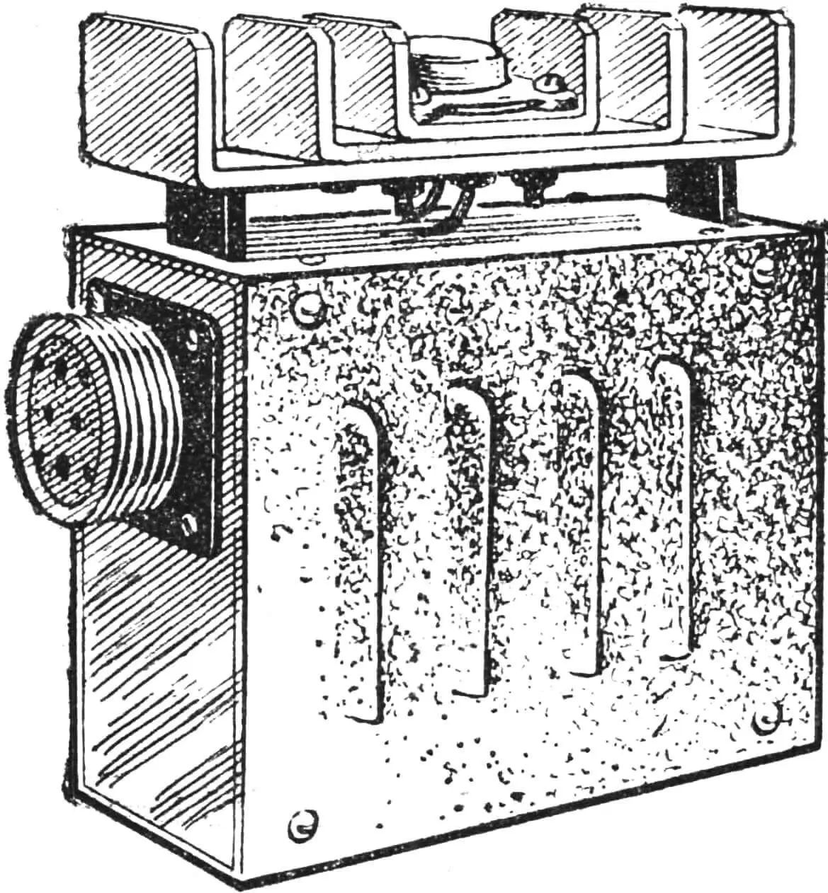
The electronic ignition circuit I developed, operating on AC current, is installed (Fig. 1) on a “Voskhod” motorcycle. The machine has already covered more than 30,000 km. The engine starts easily, quickly gains RPM, and there is no sparking on the breaker contacts. The device works as follows. When the breaker contact (Fig. 2) is closed, transistor V5 is open, voltage is applied to winding I of transformer T1 and capacitor C2 is charged. Thyristor V11 is closed at this time. As soon as the breaker contact breaks, V5 closes and voltage is not applied to T1. At this time, capacitor C1 is charged, the charging current of which opens thyristor V11. Capacitor C2 discharges through V11 to ignition coil L1, and a high voltage pulse appears on its secondary winding. Thus, while the transistor is open, the thyristor is closed, and vice versa.
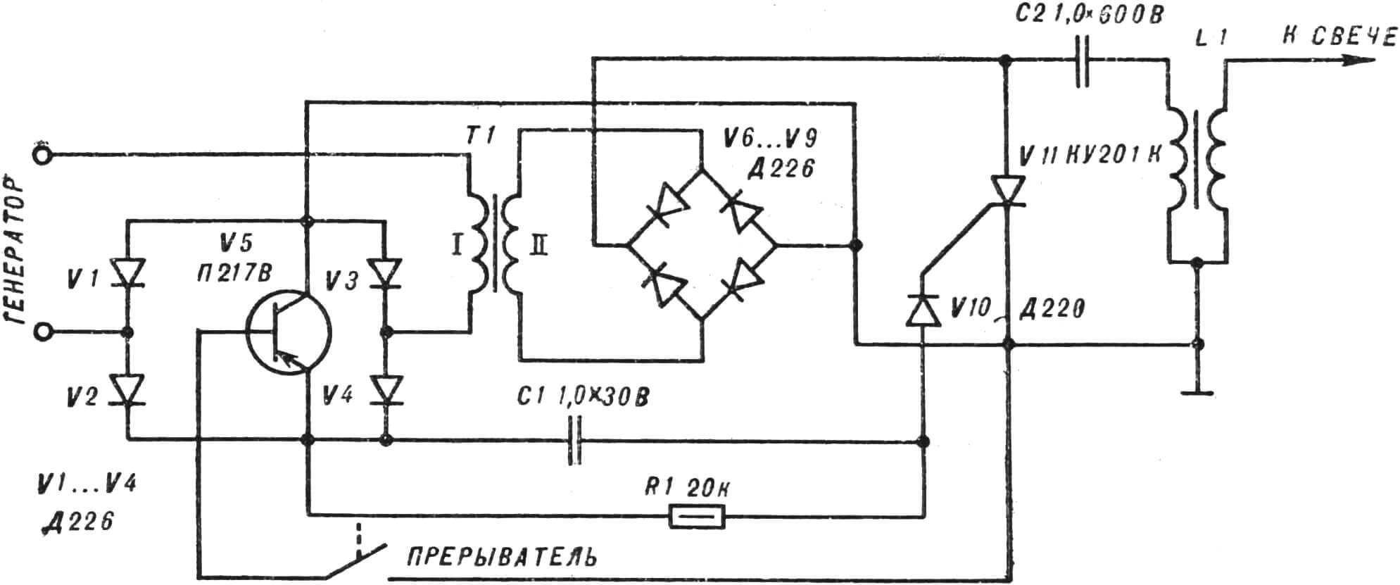
The circuit is simple to manufacture and does not require modification of the motorcycle’s contact ignition system. Transformer T1 has the following data: core Ш16Х10, winding I contains 300 turns of ПЭВ-2 0.27 wire, and winding II — 4800 turns of ПЭВ-2 0.12.
The thyristor ignition circuit is made using printed circuit board method on the board shown in Figure 2.
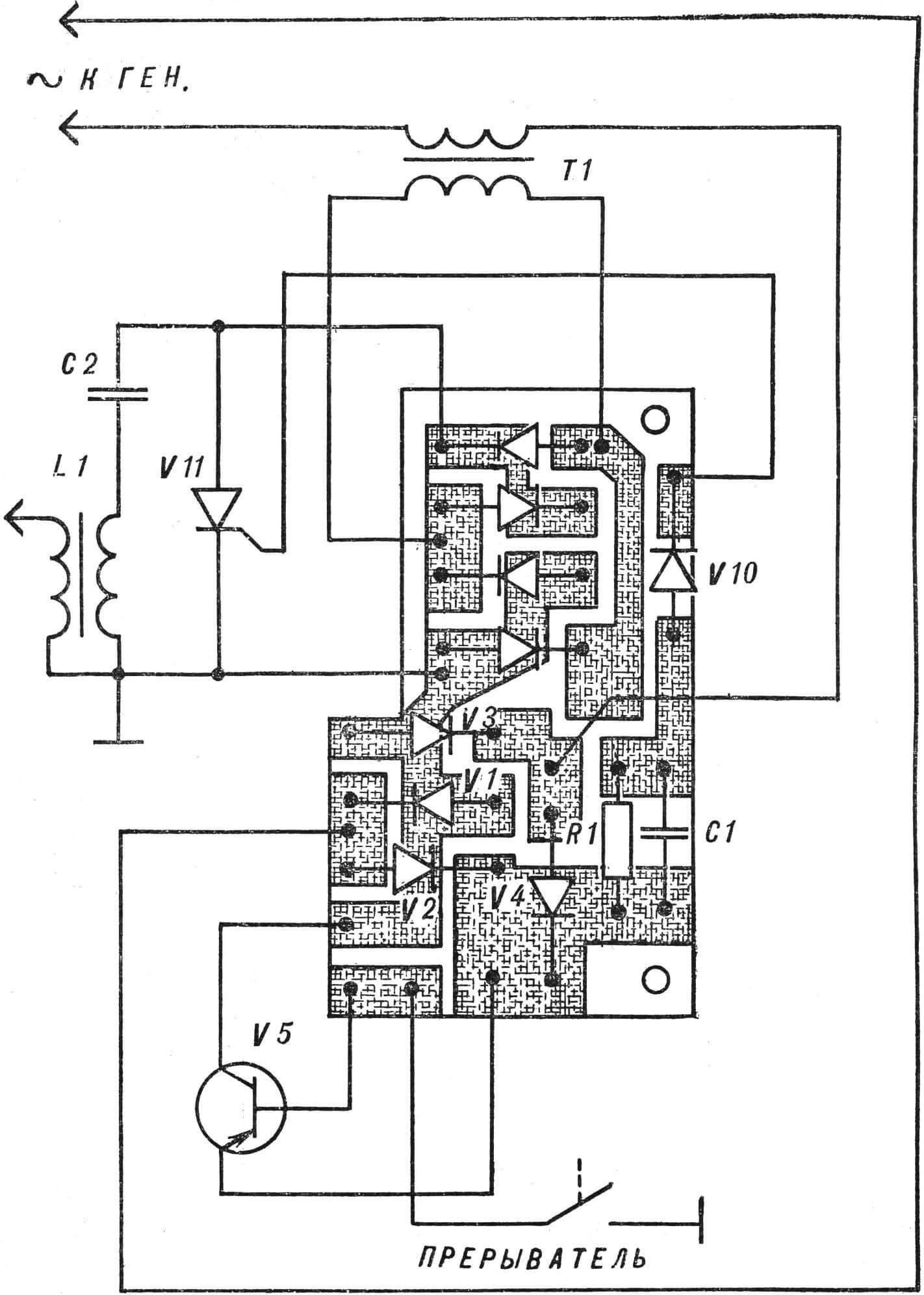
The board, transformer, capacitor C2 and thyristor are placed in a metal case measuring 120X90X50 mm. The transistor is mounted on a heatsink (see Fig. 1) with a dissipation area of 150 cm2 or directly on the case. Diodes Д226 can be replaced with Д7Ж, Д226Б, thyristor КУ201 — with КУ201Л, КУ202К, КУ202Л, transistor
П217В — with П216 with any letter index or П210. By varying the resistance of resistor R1 within small limits, continuous spark formation on the spark plug is achieved at a frequency of 100—120 Hz. Moreover, there should be no sparking on the breaker contact plates. This indicates a transistor malfunction.
L. POBEREZHNYUK
Recommend to read
 THE SHIP IS ON THE TABLE
To make a model of the ship, which would be a decoration in the house I wanted for a long time. But all that couldn't decide what military ship to take over the original ones seemed too... START FROM UNDER THE WATER
Japanese seaplane E14Y. The first production Е9W1 hydroplanes equipped with boats I-7 and I-8, after which in 1937 the serial production of these aircraft continued. Just released 32...
