PEDAL FOR CHAMPIONS

PEDAL FOR CHAMPIONSBike, perhaps the most common vehicle. And the fact that the most economical — there is no doubt that only two sandwiches to two hours to pedal. But is it possible to increase the efficiency of the human “engine”? With the reduction of spending “fuel”, nothing happens. Friction and the weight of the machine is reduced almost to a minimum. There is also a “box of speeds” the device for changing the gear ratio by switching the circuit to a small or large sprocket. It remains only to lengthen the levers of the pedals, but experts adamantly claim that their optimal length — 170 mm.
An original solution was proposed in recent years elliptical sprocket. Readers familiar with the details of this invention. Using the ellipse ratio is changed cyclically, better adjusting of the pedal mechanism under the human, but… not easier work.
 
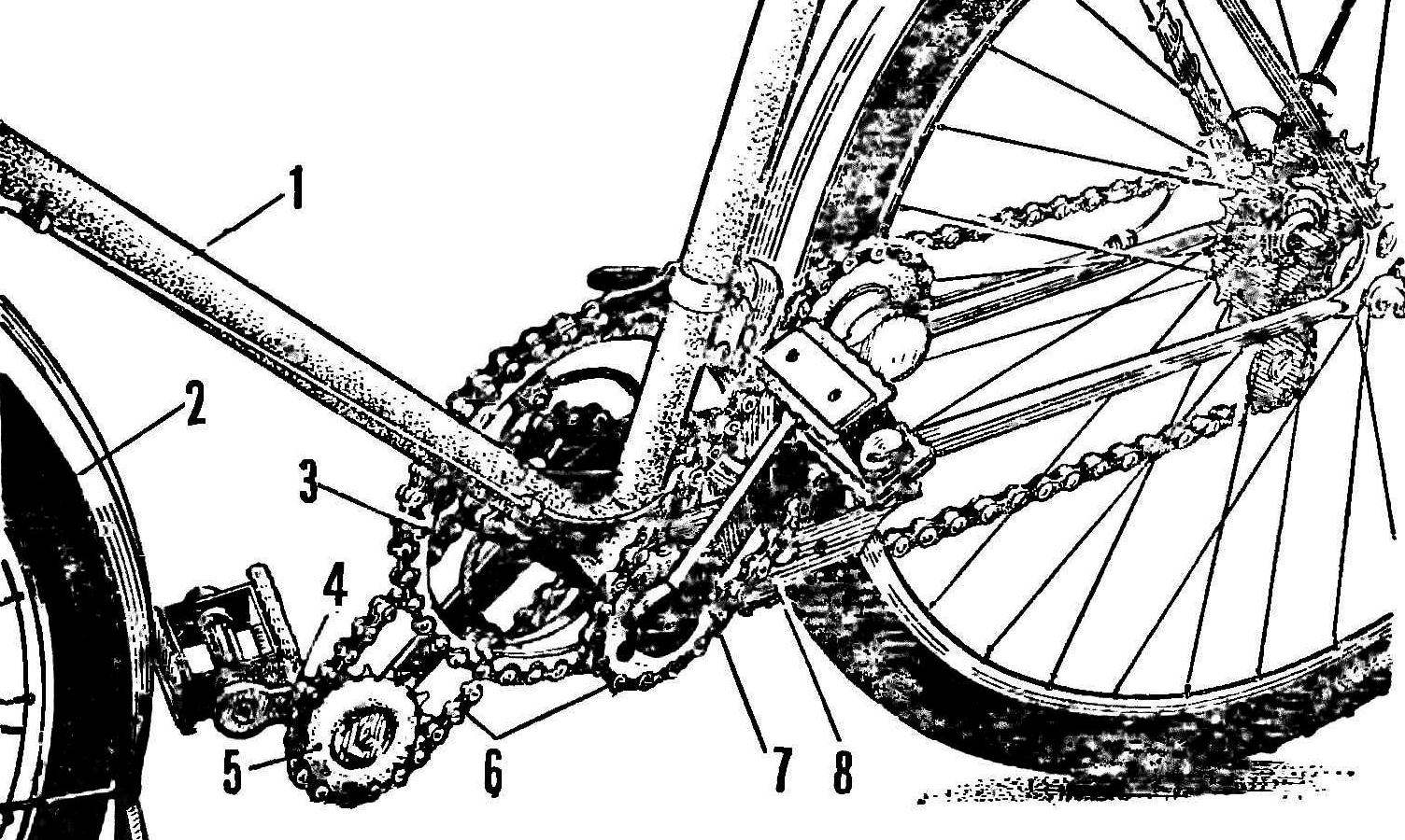
In the present device (Fig. 1) UDA the axis to synthesize the advantages of elliptical gears and a “long” levers: here the torque increases when under pressure from the charm levers like extended, describing at the same time Ellipso curve, although the drive sprocket maintains the correct circumference. This achieves a gain in power and eliminates the uneven change of the transmission ratio; the legs describe a circle of optimal radius of 170 mm.
 
Fig. 1. Here is a new pedal mechanism
Fig. 1. Here is a new pedal mechanism:
1 — the bike frame 2 — front wheel 3 drive sprocket, 4 — foot extra leverage, a 5 — star lever, 6 — additional chain transmission, 7 — rod, 8 — bracket.
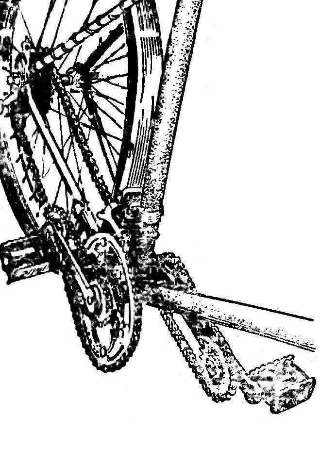
 
DEVICE
 
The pedal mechanism (Fig. 2) there has not been without the usual main lever — rod 4, on the hub which fits over the auxiliary sprocket 9. It is mounted in a fixed position relative to the Bicycle frame through the bracket 11. To the free end of the connecting rod hinge is mounted on the auxiliary extension arm 12 to the pedal 13. On the selector shaft 12 fixed to the second auxiliary sprocket 14. Both gears have the same number of teeth and are linked by a chain.
 
THE PRINCIPLE OF OPERATION
 
Fig. 2. The main nodes of the upgraded veloplivd
Fig. 2. The main nodes of the upgraded veloplivd:
1 — mounting strap sprocket, 2 — clip, 3 — key, 4 — key leverage (rod), 5 — pin, 6 — bushing, 7 — roller, 8 — bearing, 9, 14 auxiliary sprocket, 10 — prop, 11 —*
brackets. 12 — lengthening the lever 13 pedal. 15 — ball bearing 16 — bolt, 17 — bushing auxiliary sprocket, an 18 — washer. 19 — the axis of the extension arm.


When pressing on the pedal 13, the main lever starts to spin, the sprocket 9 (via chain and the second auxiliary sprocket 14) holding the extension arm 12 is always directed forward and horizontal. When misrepresented overall trajectory of the extension arm is an ellipse, in the “front” half of which the greatest radius has the pedal and a rear — hinge of the lever. Due to this, the forward control pedal allows you to press on it with maximum force it on the most effective part of the way — from the top dead point TO the bottom, that is, when the main arm is extended like that and provides a gain in force. Though actually when pedaling they describe a perfect circle with a radius equal to the length of the connecting rod (optimal length — 170 mm), but forward on the length of the auxiliary lever (Fig. 3).
 
MANUFACTURER
 
For simplicity, consider the details in order, as they are marked in figure 2. Strap 1 is made of capiranno steel with a thickness of 5 mm. thereto by bolts sprocket crankset. Depending on its diameter and shape of the middle part of choosing the carrier part of the plate (in the figure not given). Clip 2. Two such staples are made of capiranno steel with a thickness of 3 mm. Them carrier plate is fixedly attached to the hub of the right main lever — screw M6 X 8 countersunk head. Key 3. Need two, from steel St45; their sizes are determined by neck in the axis of the connecting rod and the size of the keyway of the hub. The main lever 4. Two of them — right and left, are made of steel Ст40Х. They are bound to their arms (4) welding. Groove for dowel bushings should be the same side with respect to the lever. The hole for the pin (5) in the last drilled after welding through a bushing. Pin 5 of spring steel 65G without additional heat treatment. Sleeve 6. There are two — the right (for right arm) and the left (for the left). Material — steel STD. Roller 7. Used rollers d 2.4 X 10.5 mm cross from the old car VAZ-2101.
 
A bearing sleeve 8. Will need two steel Ст40Х. Four holes d 5 mm are drilled in them at the same time with the holes on the auxiliary sprocket 9 and the bracket 11 of the support sprockets 9 and 14.
 
All four of them. They are standard, in the hollow rear wheel has 19 teeth (sold in auto parts stores for bikes). Two asterisks (9) holes chiseled to d 39 mm. Can be manufactured as one piece together with the bearing bushing 8 and bearing sleeve 17. In this case, the number of teeth must not be less than 13. Basic (without teeth) diameter of a sprocket is 52.5 mm, and the outer — 60,5 mm.
 
The support 10. Is secured by two M3 screws to the left bracket 11 to provide sufficient front lwfg between the bearing sleeve and the hub of the left main lever.
 
The bracket 11. With their help, the support sprockets are mounted movably relative to the frame of the bike. They consist of three parts: shoulder and two brackets, which are curved in accordance with the diameter of the frame. The material of both brackets and four clamps — dekamerona steel with a thickness of 3 mm. Bracket fasten screws M5, and after will be advised of their bending on the frame are welded.
 
Lengthening the lever 12. Two of them: both are made of steel Ст40Х. At one end of each hole to the pedal with thread M14, which should be the same name: right — right, left — left. At the other end of the hole axis (19); it is welded. For greater strength along the parting line of the axis of the lever can be done by one or two deaf holes 4 d,9X9 mm before welding them driven into stumps steel rod d 5 mm, performing the role of pins.
 
The ball 15. Only for bearings of the extension levers would need 84 pieces d d 3 or 3.2 mm.
 
The bolt 16. Two of them, the size М6Х X 10 mm — for fixing the sprocket on the arm.
 
The sleeve 17 under the auxiliary star — two pieces — steel Ст40Х. Three slots are machined along the periphery of the exposed portion of the sprocket 14.
 
Puck 18. Two of capiranno steel 2 mm thick; inner and outer diameters respectively of 6.5 mm and 38 mm.
 
ADDITIONAL RECOMMENDATIONS
 
For the manufacture of the device is given. tion drawings must have a hollow bottom bracket axle. You can use the axis with a square-tapered edges, but the holes in the hub of the crankset must meet its size and the space between the hub of the carriage of Bicycle hubs and cranks must be at least 1 mm.
 
Play is essential for the normal rotation of the extension lever relative to the connecting rod is achieved by selecting the thickness of the steel washers (washers) mounted between the axis of the extension arm 12 and washers 18.
 
Fig. 3. The scheme of movement of the modernized rod
Fig. 3. The scheme of movement of the modernized rod:
A — the main lever, B — lengthening the lever.


The spacing of the main and auxiliary levers is approximately 172 mm. Below the chain had a weak tension, its size is determined during installation. How does it happen? Lengthening the lever and the sprocket are mounted on the free end of the connecting rod On the axis of the carriage are mounted (not permanently) other auxiliary sprocket and the bearing bushing 8 on the hub. On both sprocket worn chain with a length of 590 mm, is stretched, after which the lever and hub are welded to each other. When removing the pin 5 is removed, the hole MB tightened the screw, and suitable borodkom through the hole in the Central axis of distracting the main lever (push rod).
 
A trial Assembly, before which the details 1, 2, 4, 8, 11, 12 and 17 are subjected to heat treatment (cementing). Between the connecting rod and the extension arm and between the main lever and a bearing sleeve inserted plastic seals is made of suitable diameter with a thickness of 1 mm.
 
* * *
 
Pedal mechanism with automatic lengthening of the levers is recognized as invention and protected in Bulgaria by the copyright certificate. Everyone who tried this new product, celebrating not only the constructive originality of solving tasks, but also achieved thanks to politely tion effect: “pickup” bike-cars, equipped with such a mechanism, the more easy passage of heavy trails and hill climbing.


Recommend to read

  • PROFILE -UNIVERSALPROFILE -UNIVERSAL
    As you know, W-shaped plastic, wooden or metal profile furniture used as a guide slider for sliding glass doors. However, these profiles may well be used as shelf supports in cabinets...
  • SCRAPER-TIMESCRAPER-TIME
    Gutters on the roofs of the cottages have to be cleared of debris not too often— usually in the autumn, during leaf fall. So it makes no sense to have this special tool. Instead, you...