When building amateur aerosleds, gliders and hovercraft, the greatest difficulty is usually choosing the right engine. Standard production engines often fail to satisfy home‑builders in many respects, particularly in terms of specific power.
The most radical way to solve this problem is to build homemade engines using parts from serial motorcycle engines. Readers of “M‑K” are familiar with such engines as the BB‑1 designed by G. Beloshapkin and L. Buyanov, the engine by L. Komarov and V. Fedorov, and the AG‑1 designed by A. Gerashchenko.
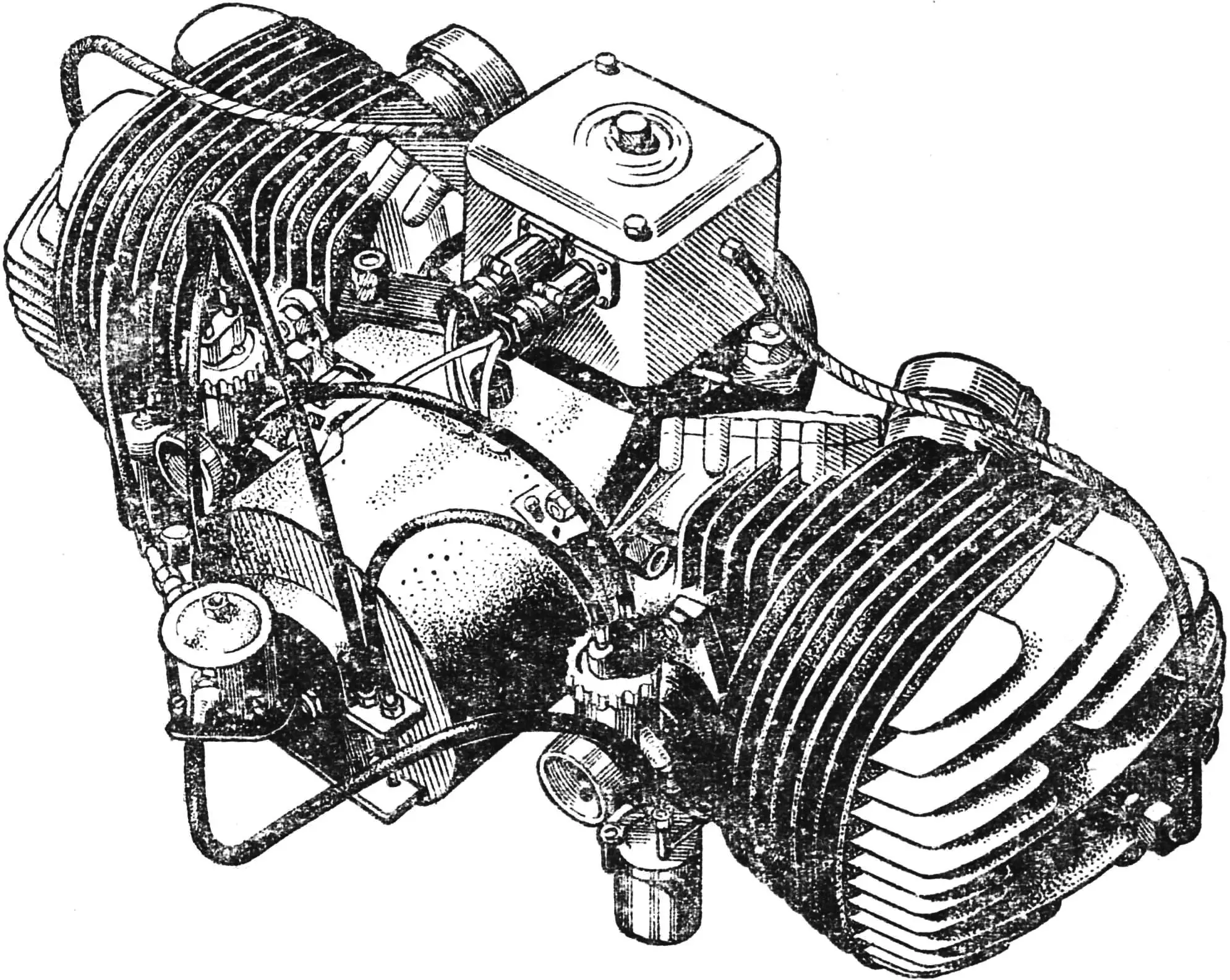
Here we will discuss the design principles and manufacturing technology of two‑cylinder opposed engines, also with maximum use of standard parts. As an example we will consider an engine built and tested by A. Antipin from the settlement of Priyutovo (Bashkiria).
It should be noted that, when A. Antipin’s engine was reviewed at the M‑K experimental design bureau, a number of upgrades were introduced. Their purpose was to increase reliability, simplify machining of parts and eliminate some technological operations. In addition, the design changes make it possible to significantly improve the manufacturing accuracy of the main parts, which increases the engine life.
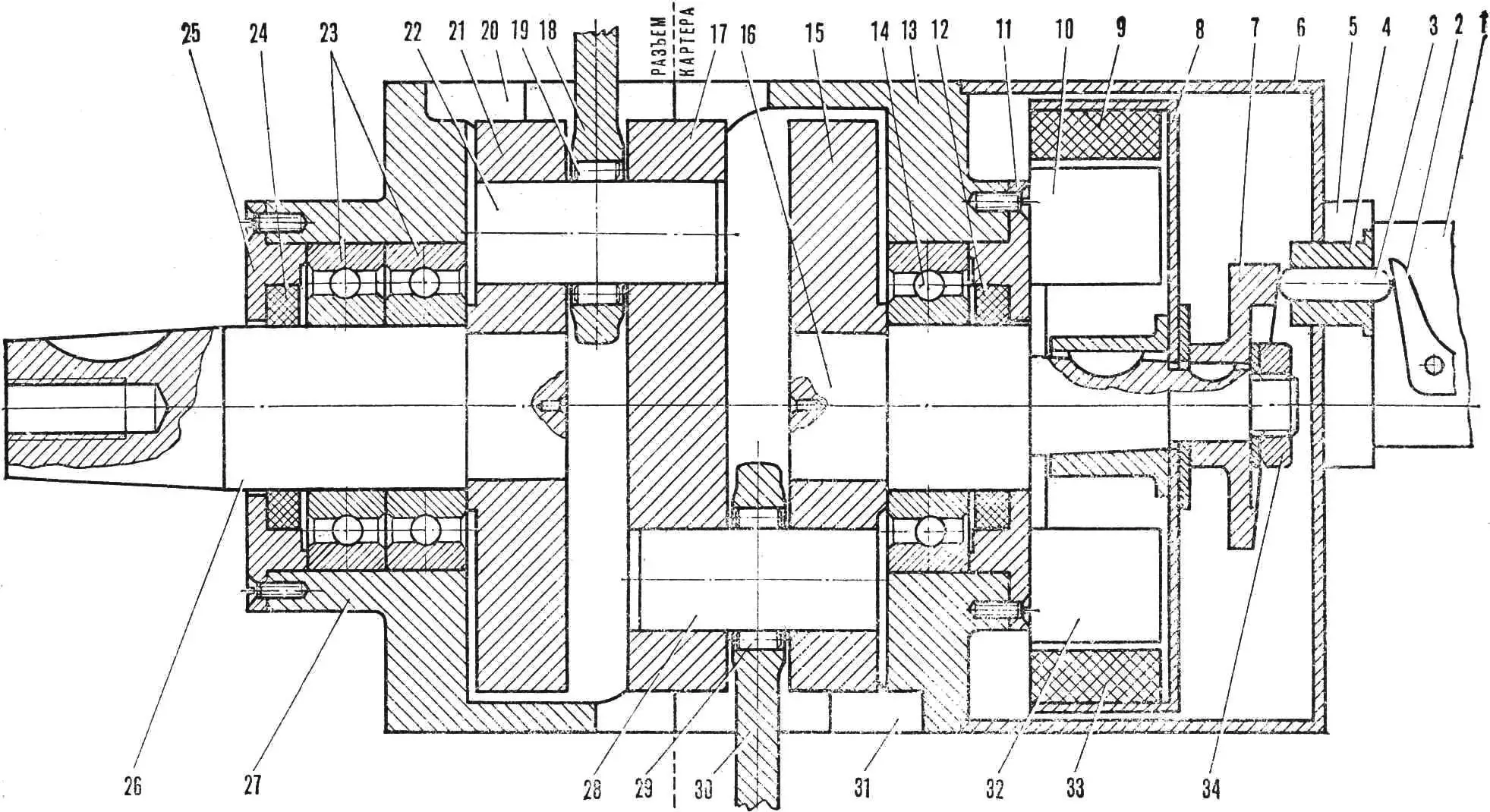
1 — fuel pump housing, 2 — fuel pump lever, 3 — fuel pump drive rod, 4 — rod bush, 5 — spacer, 6 — magneto cover, 7 — fuel pump eccentric, 8 — magneto armature housing, 9, 33 — armature magnets, 10, 32 — armature windings, 11 — front main bearing cover, 12, 24 — seals, 13 — front crankcase half, 14, 23 — main bearings No. 208, 15 — front crank web, 16 — front main crank pin, 17 — middle crank web, 18, 30 — connecting rods, 19, 29 — rollers of the lower connecting rod bearings, 20, 31 — bores for cylinder liners, 21 — rear crank web, 22, 28 — pins of the lower connecting rod bearings, 25 — rear main bearing cover, 26 — rear main crank pin, 27 — rear crankcase half, 34 — nut securing the fuel pump eccentric.
There is no doubt that a two‑cylinder engine with opposed cylinders has a number of advantages over inline twins made from two single‑cylinder units and, even more so, over single‑cylinder engines. It is much better balanced, because the reciprocating motion of the two pistons is opposite, and therefore the inertia forces are mutually balanced. Reliability is higher and the engine is easier to start. Minor faults in one of the cylinders do not disable the engine and, at the very least, allow you to “limp” to a repair site. Add to this the lower weight and overall dimensions, the simplicity of the ignition system and good cooling of both cylinders, and the conclusion is obvious: it is worth tackling an opposed engine!
The design of the proposed engine (Figs. 1, 2) is simple. It can be assembled using parts from the engines of IZH‑P‑2, IZH‑P‑3 or IZH‑56 motorcycles. For such an engine, only the crankshaft and the crankcase need to be manufactured from scratch.
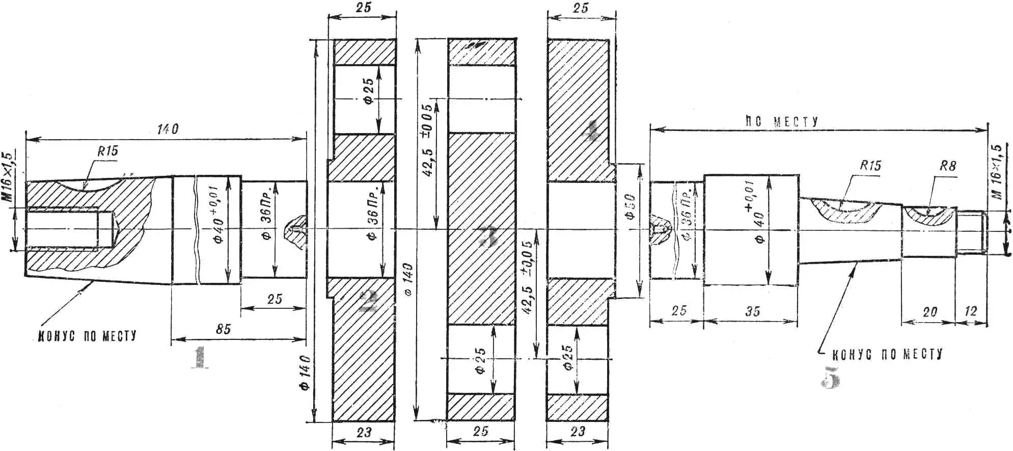
1 — rear journal, 2, 4 — outer webs, 3 — middle web, 5 — front journal.
The crankshaft (Fig. 3) is made built‑up. The main journals and the lower connecting rod pins are installed during assembly. Steels 18KhMYuA or 40Kh are recommended for all parts.
Blanks of the main journals with center holes are turned on a lathe and have an allowance of 1.0 mm per side for further machining (except for the seating surfaces intended for pressing into the crank webs, which are bored immediately to the nominal size). The three discs that form the crank webs have an allowance of 0.5 mm per side. They are then ground on a surface grinder and the holes for the main journals and the pins of the lower connecting rod ends are laid out.
The holes themselves are drilled and bored to the nominal dimensions on a faceplate or in a four‑jaw chuck of a lathe. Since the mating parts are pressed into these bores, their dimensions must correspond to an interference fit.
The crankshaft is assembled in the following order. First, the main journals are pressed into the outer webs using a screw press. Then one half of the crankshaft is mounted between centers of a lathe to machine the webs, tapers and seating surfaces on the journals to nominal dimensions. After that the pins of the lower connecting rod ends are pressed into the outer webs, the lower connecting rod bearings are assembled, and the pins of the lower connecting rod ends are pressed into the middle flywheel disc. To prevent the bores in the flywheel webs from wearing out, their edges are not chamfered; instead, the ends of the pins are rounded to ease insertion.
The assembled crankshaft is mounted between centers of a lathe (with the connecting rods fixed) to machine the middle flywheel disc to its nominal dimensions. Then keyways are milled on the tapers and threads are cut on the shaft ends.
Before installing the connecting rods and assembling the bearings, all parts (pins of the lower connecting rod ends and bearings) must be carefully matched by weight. The difference in weight between the sets for the left and right cylinders must not exceed 2–3 g; otherwise the engine will run with imbalance and vibration.
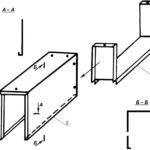
The crankcase (Figs. 4, 5) is a machined casting made of AK‑4‑1 aluminum alloy. Old automotive pistons, remelted, can serve as material for the casting.
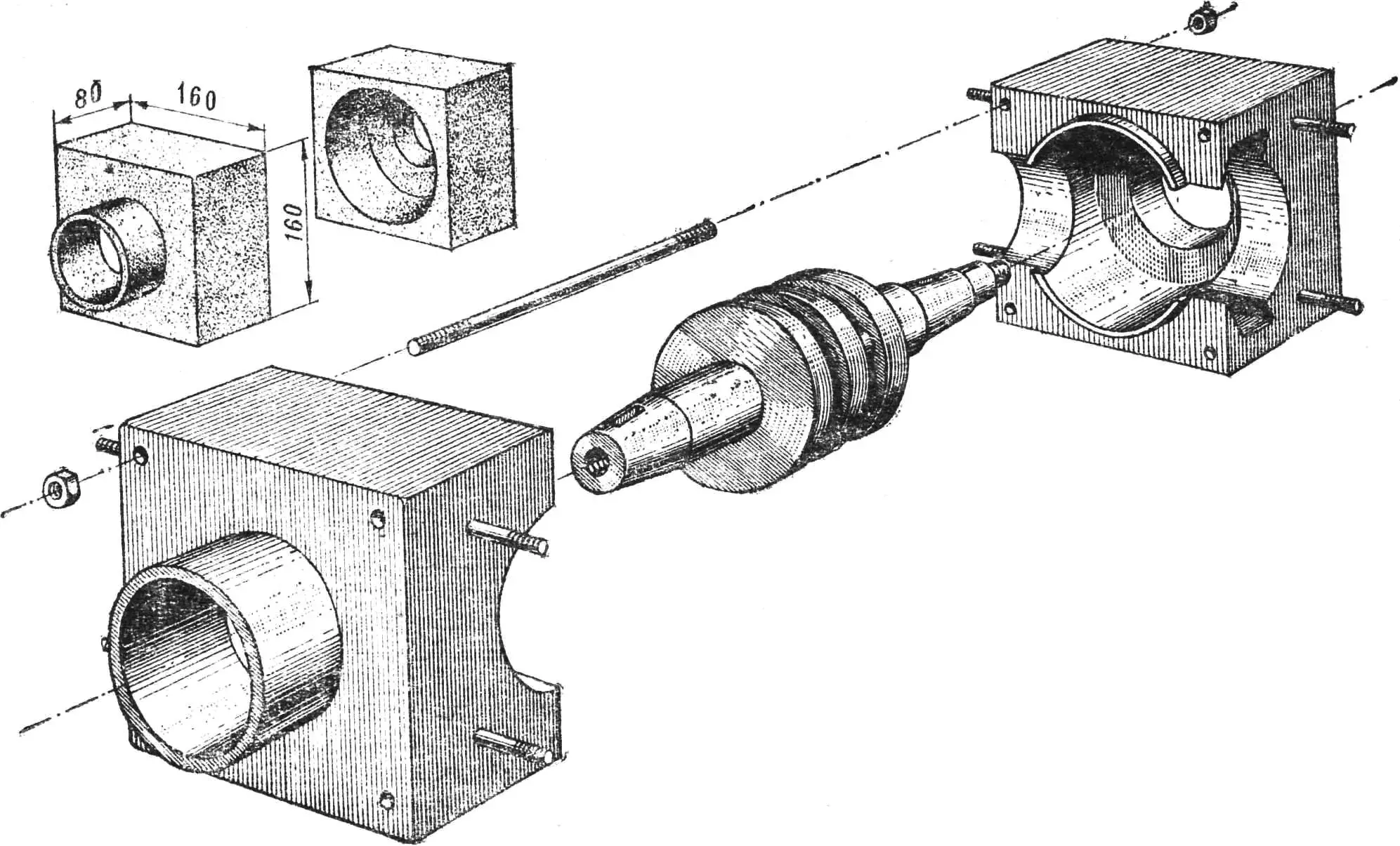
The crankcase halves are machined as follows. On a lathe, in a single setup, the internal diameters and bearing seats are bored (Fig. 5). Then the parts are assembled and holes for the tie studs and bushes are drilled. After the bushes are pressed in and the crankcase halves are tightened with studs, the outer surfaces of the crankcase are milled.
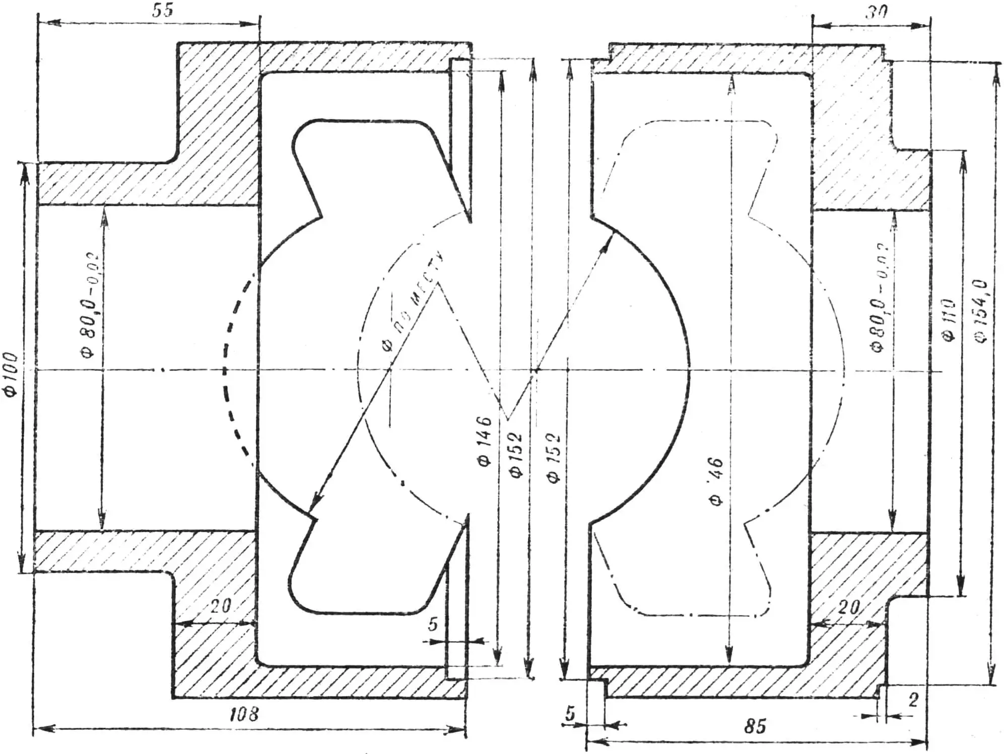
Next the crankcase is mounted in a four‑jaw chuck of a lathe to bore the seat for the magneto cover; it is centered by the bearing bores. Then the bores for the cylinder liners, studs and scavenge ports are marked out and machined on the lathe and milling machine.
Do not be surprised that many dimensions are missing from the engine drawings: most of them depend on the ready‑made parts you decide to use.
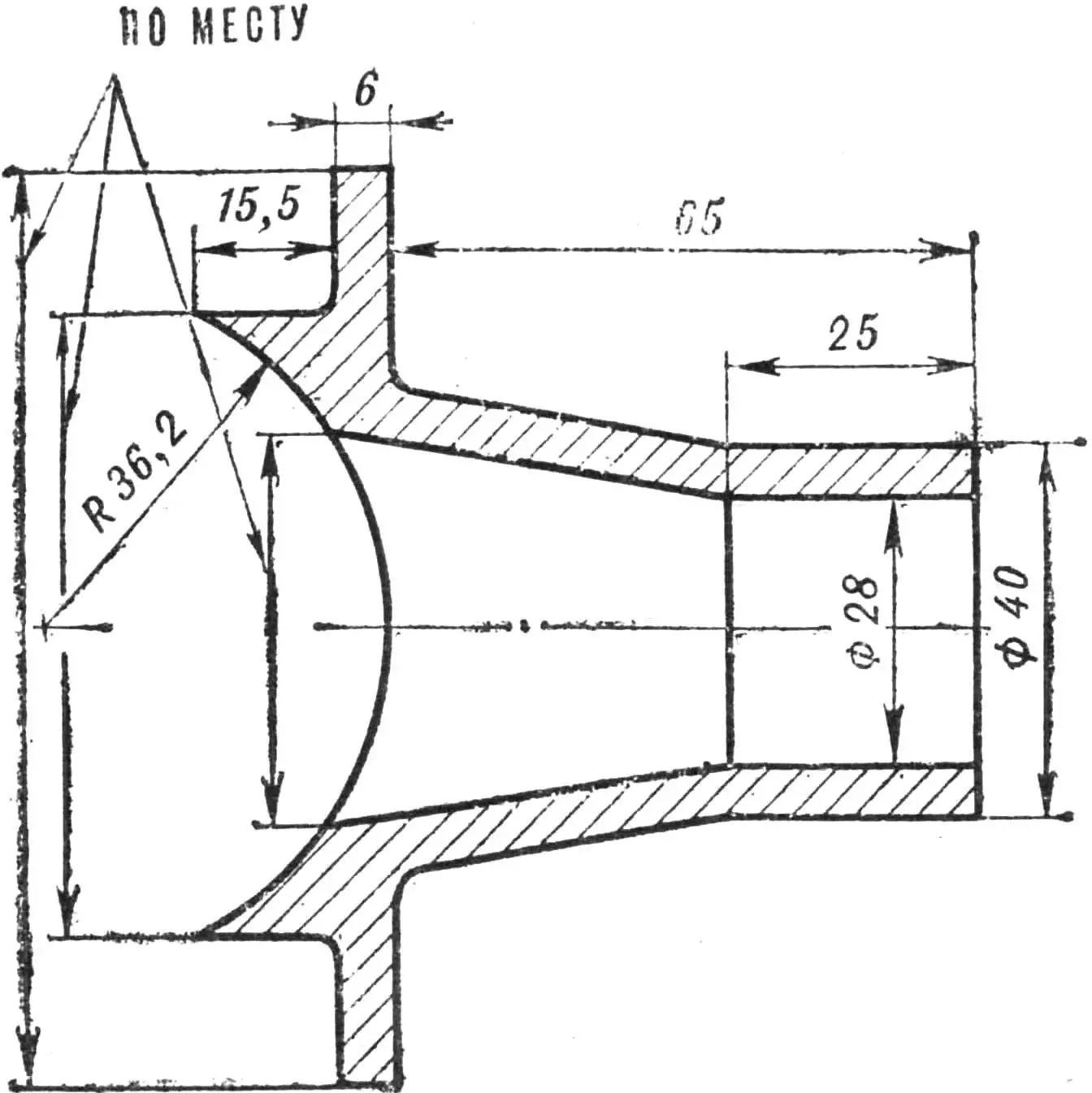
Figure 6 shows the drawings of the bearing caps and the fuel pump eccentric (from the engine of a Zaporozhets car or an outboard motor). Using the latter allows you to dispense with the original eccentric drive. In this case, the magneto cover can be made from any suitable material (for example, fiberglass).
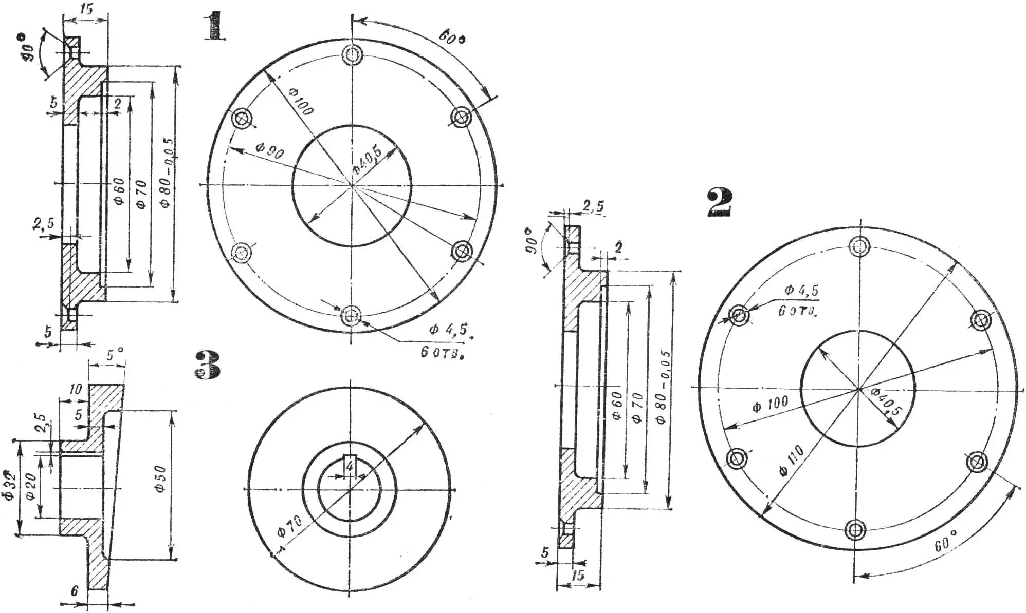
1 — rear main bearing cover, 2 — front main bearing cover, 3 — fuel pump drive eccentric.
As is known, the fuel pump of an outboard engine operates from vacuum in the crankcase, so to drive it, it is sufficient to weld a fitting into the crankcase and connect it to the pump with a flexible hose.
The best choice for the ignition system is a contactless transistor system from the Vyatka‑Elektron scooter. This system has proved itself well in service: it is stable in operation and provides a reliable and powerful spark. A distributor is not required for such an engine, since the pistons move in opposite directions and ignition occurs in both cylinders simultaneously.
The power of the opposed engine is about 28 hp, but it can be increased. Proven methods for tuning single‑cylinder engines of 350 cm³ class motorcycles can be found in sports literature on race preparation, but it makes sense to briefly mention them here as well.
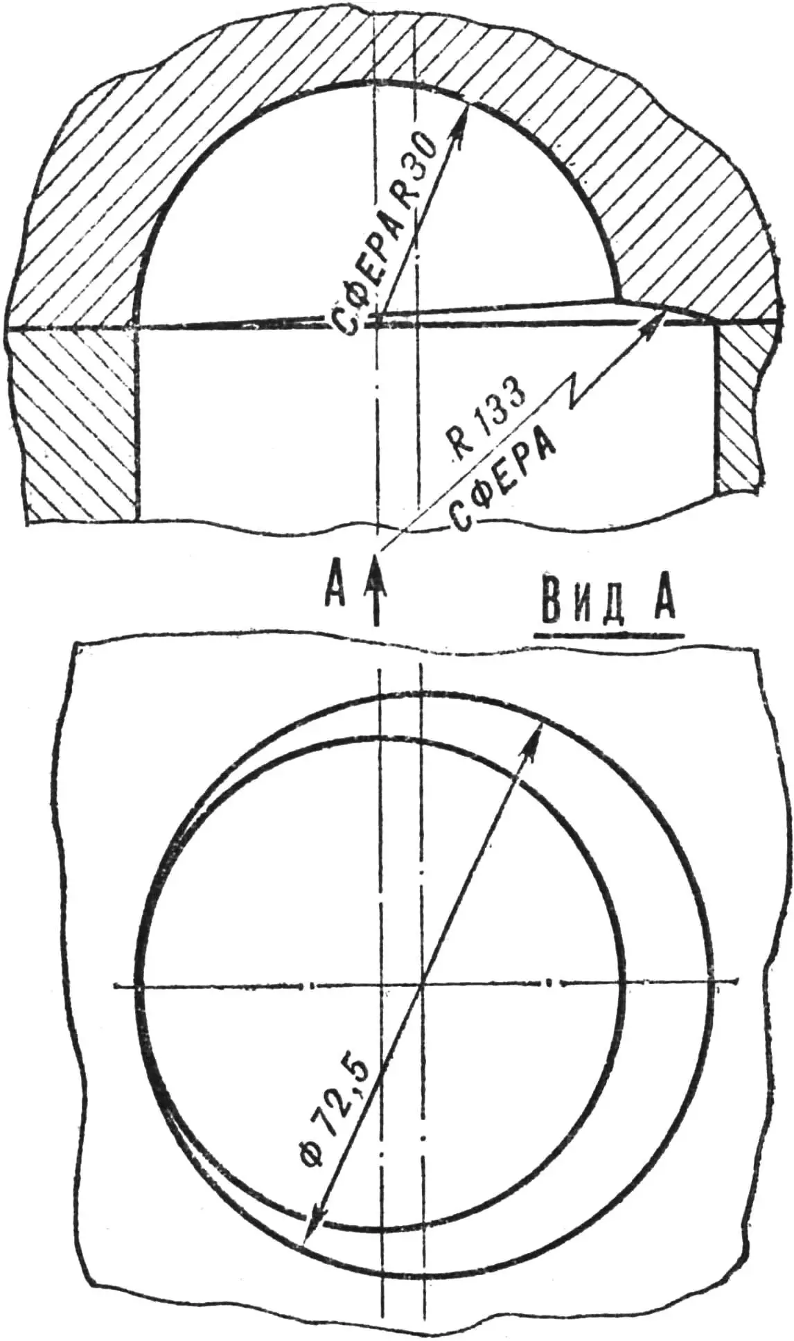
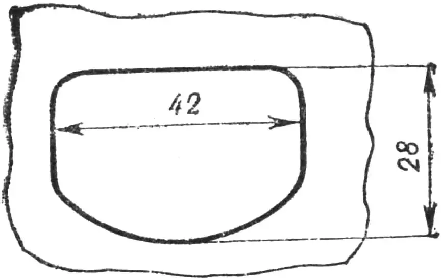
The flats on the pistons must be removed (Fig. 7). The combustion chamber shape should be changed to an offset hemispherical one with a squish band (Fig. 8); this improves scavenging, cylinder clearing from exhaust gases and ensures more uniform combustion of the mixture. There are two ways to rebuild the combustion chambers: to make new cylinder heads, or to weld up the old chambers with an aluminum alloy using an argon‑arc torch and then machine the chamber on a lathe according to the drawing. In the intake ports of the cylinders, the partitions are removed and their cross‑sections are increased as shown in Fig. 9; the lower part of the ports is rounded.
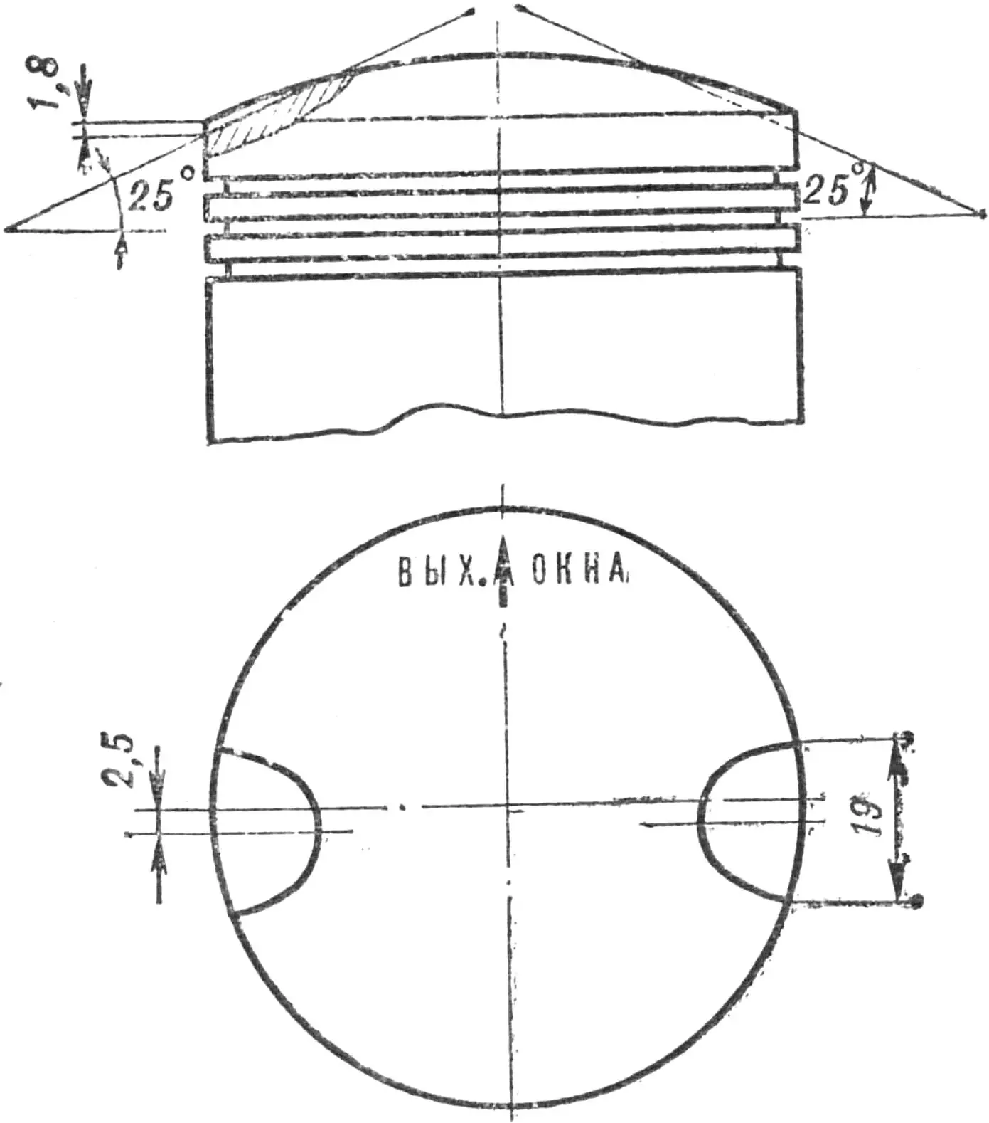
The intake manifolds should be made new and tuned (Fig. 10); by choosing the optimal length, they increase the volumetric efficiency. The exhaust phase duration must be increased to 144°; to achieve this, the exhaust ports are raised by 1.5 mm.
These operations usually increase the power of a stock IZH‑P‑2 engine from 14.8 hp to 18.4 hp; therefore, the power of the two‑cylinder opposed engine, after tuning, will rise to about 36 hp at the same compression ratio (6.5).
The most suitable carburetors for this engine are the K‑23B type or similar, with a diffuser diameter of 27.5 mm.
The fuel mixture should consist of gasoline with an octane rating of at least 80 (for example, AI‑93) and aviation oil MS‑20 or MS‑22 mixed in the usual ratio of 1:25 by volume.
Bear in mind that the service life of the tuned engine will inevitably be shorter than that of the prototype, because it has to operate in a harsher thermal regime and under higher loads.
The opposed two‑cylinder engine can also be built on the basis of other motorcycle engines such as M‑106, Voskhod or Jawa‑350, with corresponding changes to the dimensions of the crankcase, crankshaft, bearings and so on.
Here are a few recommendations for those who wish to use the opposed engine to drive an airscrew. Always remember that maximum power can only be obtained at the rated crankshaft speed (in our case 5000–5500 rpm). Therefore, if the propeller is too “heavy” aerodynamically, the engine will not reach the maximum power mode.
It is recommended to transmit torque to the propeller through a reduction gearbox with a ratio of 1.2–1.5. This will reduce the propeller speed to 2500–3000 rpm, while the tip speed of a 2000‑mm‑diameter propeller will not exceed the critical 300 m/s. Under these conditions the propeller operates with maximum efficiency and minimum slip.
Using a reduction gearbox also eliminates undesirable axial loads on the crankshaft. If the engine is used to drive a propeller without a reduction unit, a radial‑thrust bearing must be installed on the main crank journal; the standard radial bearing will quickly wear out and fail.
“Modelist‑Konstruktor” No. 6’78, F. Kizelev
It’s hard to imagine urban and rural life without running water nowadays. Well, if there’s no centralized water supply and a well is nearby, the simplest solution is to use an electric pump to lift water. However, that’s only half the job. A home water supply system should include a storage tank, automatic pump control elements, and a distribution network. That’s why engineering solutions here can be very diverse. Our readers share some of them today.
WATER PRESSURE… BATHTUB
The installation of a traditional scheme with an upper pressure tank (see fig.) is most conveniently placed in the attic of a country house. Choose a large tank—about 200 liters—preferably made of stainless steel or duralumin. An ordinary barrel must be thoroughly coated inside with waterproof paint to prevent corrosion. I used an enameled bathtub as a water pressure tank. Although it’s quite heavy, it has a solid volume, doesn’t rust, and its outlet and overflow holes are convenient for connecting to the system.
Scheme for equipping a country house with an autonomous water supply:
1 — water intake with filter, 2 — electric pump, 3 — well, 4 — supply pipe, 5 — gas cylinder, 6 — return pipe of water heating system, 7 — radiator, 8 — gas water heater, 9 — expansion tank, 10 — feed pipe, 11 — gas pipe, 12 — pump control unit, 13 — box, 14 — pressure tank (bathtub), 15 — float, 16 — lever, 17 — thermal insulation material, 18 — top cover, 19 — control elements compartment, 20 — control rod with flag, 21 — upper level sensor, 22 — lever pivot axis, 23 — lower level sensor, 24 — overflow pipe, 25 — solenoid valve, 26 — gas column, 27 — to cold water consumers, 28 — to hot water consumers, 29 — sewer pipe, 30 — drain well.
To operate the home water supply year-round, the tank will need to be insulated. Enclose it in a wooden box and fill the gaps between its walls and the bathtub with insulation—sawdust, slag, expanded clay. The bathtub should be covered with a wooden lid on top, and a box for automatic control elements—level sensors—should be installed on it.
To automatically maintain a constant water level in the tank, equip the bathtub with a regulating float device. Its design can be very diverse and depends mainly on the switches used. Non-contact switches are considered the most reliable, so I used two BVK-type switches. A lever with a float at the lower end is hinged in the lid brackets and, when the level in the tank changes, moves control rods with aluminum flags—glued foil strips—with its upper arm. The lever dimensions and sensor positions are chosen so that they activate at the minimum and maximum water levels in the tank.
A country house with such a water supply should also be supplemented with a sewer system. For this, dig a pit 1.5—2 m deep in the yard 10—15 m from the house and concrete or brick its walls. It’s even simpler to use a section of steel or concrete pipe Ø 700—1000 mm for this purpose. Sewer pipes for draining used water should have Ø 100—150 mm. They should be laid in the ground at a depth of at least 600—700 mm with a slight slope toward the collection well.
If your village has gas cylinder exchange or centralized gas supply, your water supply will provide the house with all the amenities of a city apartment. With gas water heaters like AGV-80, AGV-120—water heating, and with a gas column—hot water for household needs. The only addition to the water supply system in this case is the installation of a solenoid valve that closes the supply pipe from the pressure tank. It’s necessary so that water flows to the column directly from the pump. In this case, its pressure is higher than when supplied from the pressure tank, and the gas regulator valve will work reliably.
N. KHOREV, st. Doskino, Gorky Region
UNDER AIR PRESSURE
Installing a water pressure tank in the attic is perhaps the simplest solution, but it seemed insufficiently perfect to me. After all, to get good pressure, the tank must be raised quite high, and for normal operation in winter, complex thermal insulation is required. I decided to do it differently.
My water pressure tank made of stainless steel, with a capacity of about 60 liters, has only one outlet at the bottom. On top, it’s hermetically sealed with a textolite lid. The pump installed in the well supplies water from the intake with a check valve to the distribution system and in parallel—to the tank. Since the latter doesn’t communicate with the atmosphere, the air above the level gradually compresses and, acting as a pneumatic spring pushing water out of the tank, creates the necessary pressure. This scheme allowed placing the pressure tank in the basement. Since there are no sub-zero temperatures there even in winter, its thermal insulation turned out to be unnecessary.
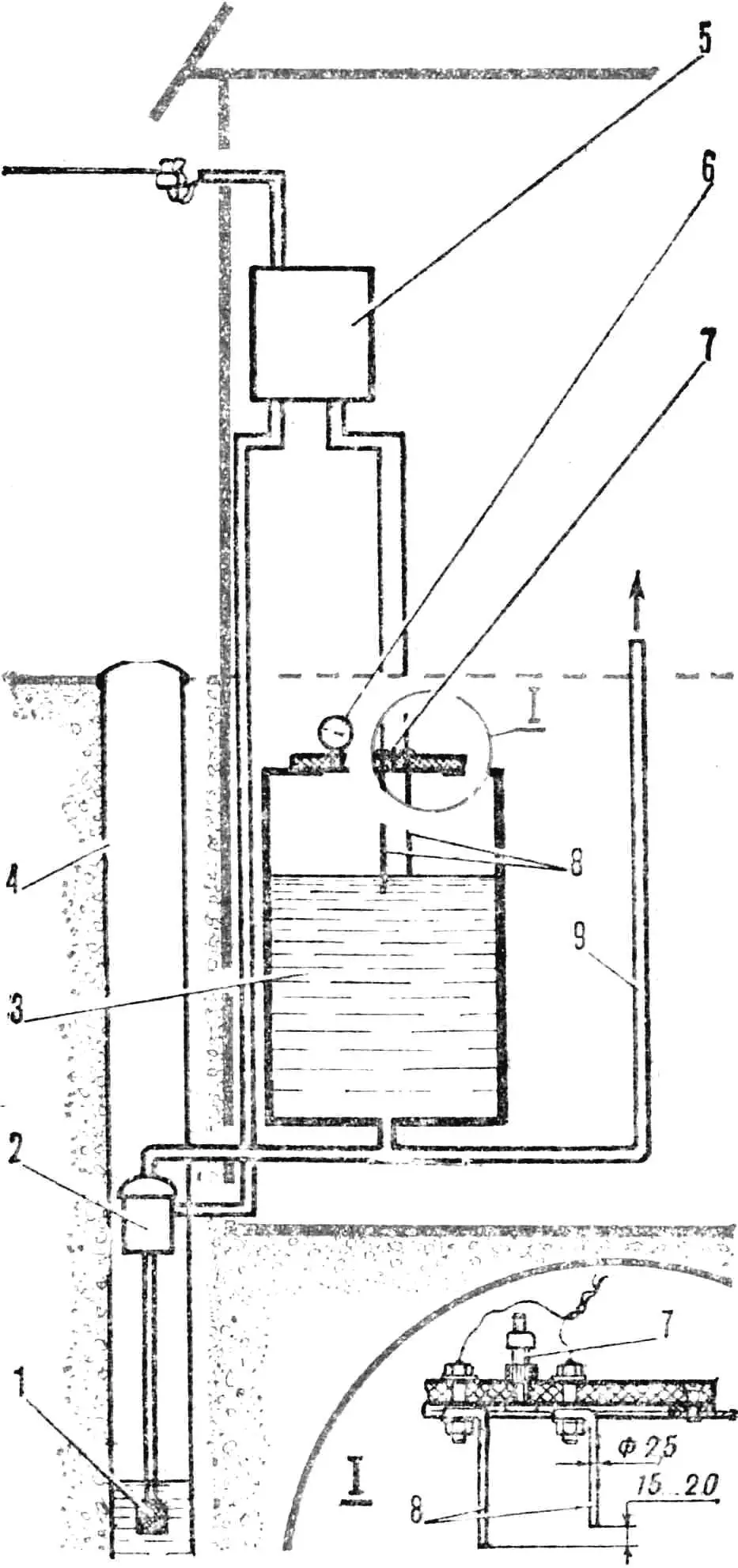
1 — water intake with check valve, 2 — electric pump, 3 — pressure tank, 4 — well, 5 — control unit, 6 — pressure gauge, 7 — valve, 8 — level sensors, 9 — distribution pipe.
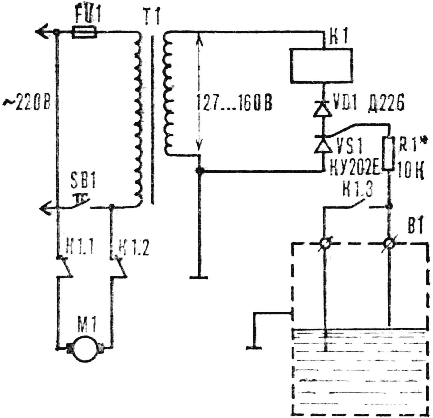
The electric pump is controlled by a simple thyristor device that automatically maintains a set water level. The sensors are two simple electrodes made of copper wire Ø 2.5 mm. They are bolted to the textolite lid of the tank so that the distance between their ends is 15—20 mm, and the upper one is at a level where the air in the tank is compressed to 1—1.5 atm.
The control system works as follows. When the water level in the tank reaches the upper, shorter electrode, the thyristor (see fig.) opens, the relay opens the contacts through which voltage was supplied to the pump motor. Simultaneously, a pair of normally open contacts connects the sensor electrodes together. As water is consumed and the level drops below both electrodes, the electrical circuit “electrodes — water — tank wall — ground” opens, the thyristor closes, and the relay releases the armature. The pump will turn on again and start supplying water.
A necessary condition for the system’s operability is the tightness of the pressure tank and the check valve of the water intake. Therefore, the lid is fastened to the tank with bolts through a rubber gasket. Holes for electrode bolts are drilled with minimal clearance and sealed with rubber washers during assembly. If compressed air leaks from the tank, the system pressure that determines the head can be restored by pumping air with a pump. For this, a bicycle or motorcycle inner tube valve is installed in the top lid. The pressure is sufficient for both household needs and garden irrigation.
V. BERDNIKOV, p. Vasilyevo, Zelenodolsky District, Tajikistan
“STARTER” FOR THE PUMP
I want to share experience with those who use centrifugal-type electric pumps to lift water from deep wells. For such a pump to always be ready for work, it must be constantly filled with water. But if the check valve of the water intake is not sufficiently tight, after stopping, water may leave the inlet pipe, which will complicate subsequent starting. A small system modification will help get rid of priming concerns. Install a small intermediate tank between the pump and the water intake, as shown in the figure.
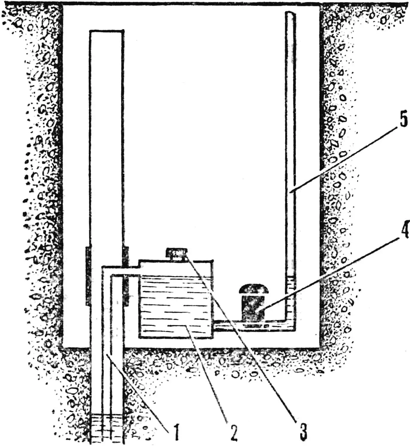
1 — water intake pipe, 2 — priming reservoir, 3 — fill neck, 4 — electric pump, 5 — pump outlet pipe.
Before the first start, fill this tank with water and tightly close the fill neck with a threaded lid with a gasket. Since the pump is connected to the lower point of the tank, and the water intake is to the upper one, water won’t leave there even with a faulty check valve, and the mechanism will always be ready for work. Moreover, if the tank is large enough, and the intake pipe is not from the very bottom point but with an offset of several centimeters from the bottom, the additional tank will also serve as a filter-settler.
«M-K» 5’86, A. POTAPOV
Recommend to read
 Multifunctional housing
For many years, I have been mounting my amateur radio homemade devices in universal cases made according to a single scheme. This is a frameless construction consisting of two U-shaped...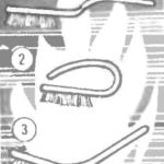 DENTAL IN THE NEW ROLE
In the practice of the house master there is often a need in a small brush for cleaning small parts, corrugated surfaces, plates or printed circuit boards. Very convenient for this...
