Elaborate on the design principles and manufacturing technology nodes this model is not worth it. As for the layout and definition of the basic parameters of the circuit aircar — all this in detail in the pages of “M-K” in the last 2-3 years. Therefore, the development was only to bring together existing information and actually translate the quantity into quality. To more thoroughly investigate that formed the basis of the selection of the geometry of this “shell”, we recommend you to get acquainted first of all with articles of the “aviation law” and “Sprinters ice kartodromo”. It is also useful to read again the material on the principles for revision of the Microdrive, “Junior” (in other literature you can’t find it).
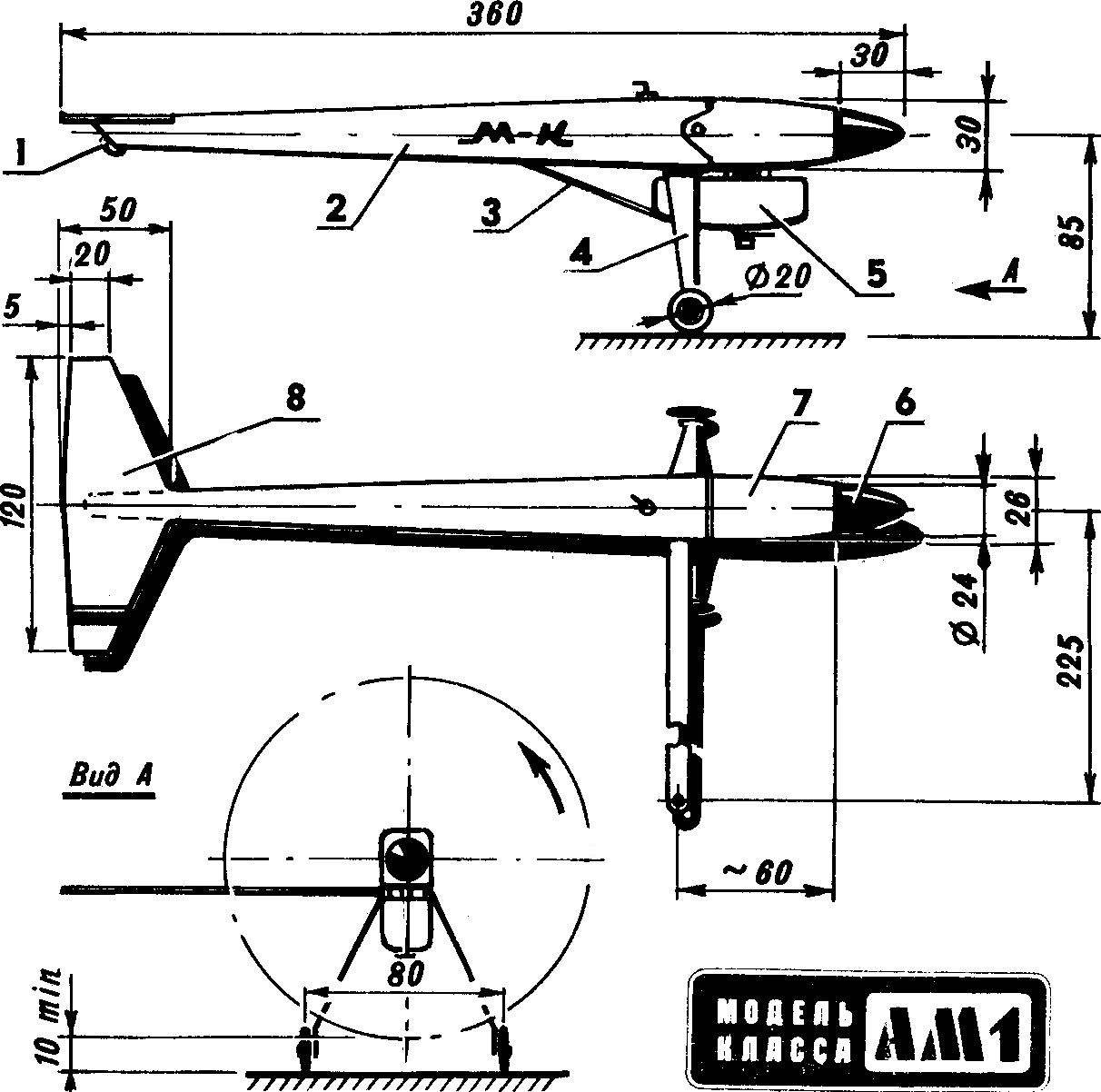
Fig. 2. The design of the model:
1 — the stabilizer, 2 — tail frame (lime 2 mm thick), 3 — the insert for mounting the stabilizer (lime), 4 — shell of the housing (cable paper epoxy resin, the thickness of veclachi about 0.5 mm), 5 — site fixation of the brace (screw M2,5, sealed with epoxy resin), 6 — intermediate frame (plywood 2 mm), 7 — fuel tank 8 — knot of the jet, 9 — tube boost tank pressure from the crankcase, a 10 — fitting valve, 11 — ring frame fairing engine (plywood 5 mm, to fit the diameter of the sock Carter), 12 — Kok Assembly, 13 — circuit the usual fairing of the lower part of the engine, 14 “checkbox” fixing screw kontrolna (steel, sheet thickness 1.2—1.5 mm, cut thread M4), 15 — adjustment screw kontrpartiya with a square head, 16 — wheel Assembly, 17 — wheel axle, 18—, 19 — brace (wire OVS Ø 2.3 mm), 20 — cord strap, 21 —force frame-motor mount, 22 — area (blank — profile 20X20X1,5 mm, D16T), 23 — wheel Ø 8 – 10 mm.
As for the model… As has been said, it is simplified to the limit while maintaining full functionality. The Assembly of parts is conducted only on plasticized epoxy resin as the only binder, is capable of providing high quality and reliability connections and long service life. The basic material for the stabilizer is selected balsa. Although in most cases, for beginner modelers, we are trying to get away from recommendations to use this acutely scarce wood, here its use is justified by the sharp decrease of the complexity of the details and gain in weight with sufficient strength. The ideal method of finishing the surface of the how stabilizer and beam housing — pasting a thin fiberglass (0.03 mm) for two-component parquet lacquer. What is important is to build the nodes all the joints are carefully treated with emery paper and degreasing with acetone. The main wheels — ready (taken from model aircraft riders, where they are used at high loads and speeds up to 200 km/h). The only revision, where they are subjected to, reducing the outer diameter of the rubber. In principle this is not necessary because in the original version have wheels Ø 26 mm.
Fig. 3. Stabilizer:
1 — ending (balsa with thickness of 2 mm), 2 — the main part (balsa 2 mm thick), 3 flange (lip section 2X2 mm), 4 — square scarf (lime 2 mm thick). The skinny fiber paper or fiberglass thickness of 0.03 mm on a parquet varnish.
Fig. 4. A mandrel for vyklicky tubular beam body (basswood, aspen or birch, surface waxing or to paste over with plastic wrap).
Fig. 5. Cord strap (D16T).
Fig. 6. Landing gear (steel, with aluminum alloy sheet thickness to increase to a 2 — 2.2 mm).
Fig. 7. Fuel tank with built-in nozzle:
1 — tube Ø 3 mm intake fuel, 2 — fuel tank (tin), 3 — bandage (tin), 4 — body nozzle (brass, bronze, outside thread M4X0,5, in on half the length of M2 — 5), 5 nut M4X0,5 (brass), 6 — spacer (brass), 7 — spring retainer needle (OBC Ø 0,4 mm), 8 needle (OBC Ø 2.5 mm on the rod to cut the threads M2,5, at the top screwed corrugated washer of the drawing tools, soldering), 9 — tube Ø 3 mm fuelling and boost (on top of the brazing ring of copper wire Ø 0.5 mm) 10 — nut M4X0,5, 11 — the wall of the tubular beam, 12 — tube Ø 3 mm fuel supply to the carburetor. Soldering together the parts: 1, 3, 4, 5, 12, then when you build the tank all the node parts 2, 6.
Fig. 8. Spinner:
1 — staff support washer, 2 — propeller, 3 — Cup-fairing (D16T), 4 — nut-fairing (D16T), 5 — a crankshaft.
Fig. 9. Wheel axle (steel, during Assembly shank Ø 3 mm rasklepat in the hole stand).
Fig. 10. Power bulkhead-motor mount:
1 — tube motor (D16T, Ø outside 5 mm, inside M3, degrease, wrap a thin thread and glue on the resin), 2 — lining (plywood 1.5 mm), 3 — pin (D16T, prepare and seal similar to that of part 1, threaded sockets M3 cutting after curing resin), 4 — enclosure (birch).
Fig. 11. Bracket axle of the rear wheels (D16T 0.5 mm thick, wrap a thin thread and after installation of the wheel seal in the tubular beam).
The engine can be limited to listing the improvements carried out: Carter has been cut for the deviation of the axis of the cylinder ago; all of the threaded socket in the crankcase is cut on the M3 with the use of oil — brand TAD-17; in the seal area of the shaft is made of the nest (for indigenous bearing) for the fitting selection pressure tank, and is used here fitting the valve; Lankan Carter cut down as unnecessary; the crankshaft bearing of crankshaft in the crankcase sealed in resin with a bronze powder. The crankshaft of the engine selected for planting in the bearings, modified only on the cheek to provide a partial balancing. Bottom cylinder, cropped, removed the flats, forming a similarity passageways extended depth. The piston is a regular, cropped bottom and bottom, and further selected from within with the help of a drill. The rod also regular, it only improved lubrication of the bottom head due to the transition from the round holes on the propyl with maloderbetovsky pockets. The balanced spool valve, the axis of the spool is fixed with a side screw M2,5; on the plane of contact with the spool on the back cover of the selected grooves reduce the area of friction. The inlet of the inlet channel designed sealing thin-walled dural tube complete removal of other protrusions. Publication “M-K” can be found, and how to modify the cooling jacket of the cylinder, and how to put it on the foil.
Special discussion deserve the power system. Rather, carburization of the fuel, since now these two functions are performed… tank. The nozzle extension was already presented in the article about racing wheel of the car, and at first aroused skepticism. But after practical testing, we began to consider better of this scheme of supplying fuel to a racing micromachines no.
A. SOLOVIEV, candidate of master of sports
Recommend to read SHAH… THE BOLT FROM THE NUT Once, when away from roads, I felt that with the machine there is something wrong, but I do not understand. I had to stop on the first encountered small's auto service station. ... IRON WILL BE EASIER The iron cord when Ironing linen constantly thwarted, trying to get his hot soles. However, if you make a special extension cord, the socket of which to attach under the Ironing Board,... 
 We offer young athletes like high-speed cord combines the experience gained in this kind of automodelisme in recent years. Sorpresa design is logical from the point of view the sole purpose of achieving the highest speeds, that is, turning the aircar “Frank” sportsread. But if to argue from the point of view of an engineer, simplicity is the evidence of correctness of the choice of scheme design and, if it reaches the desired result.