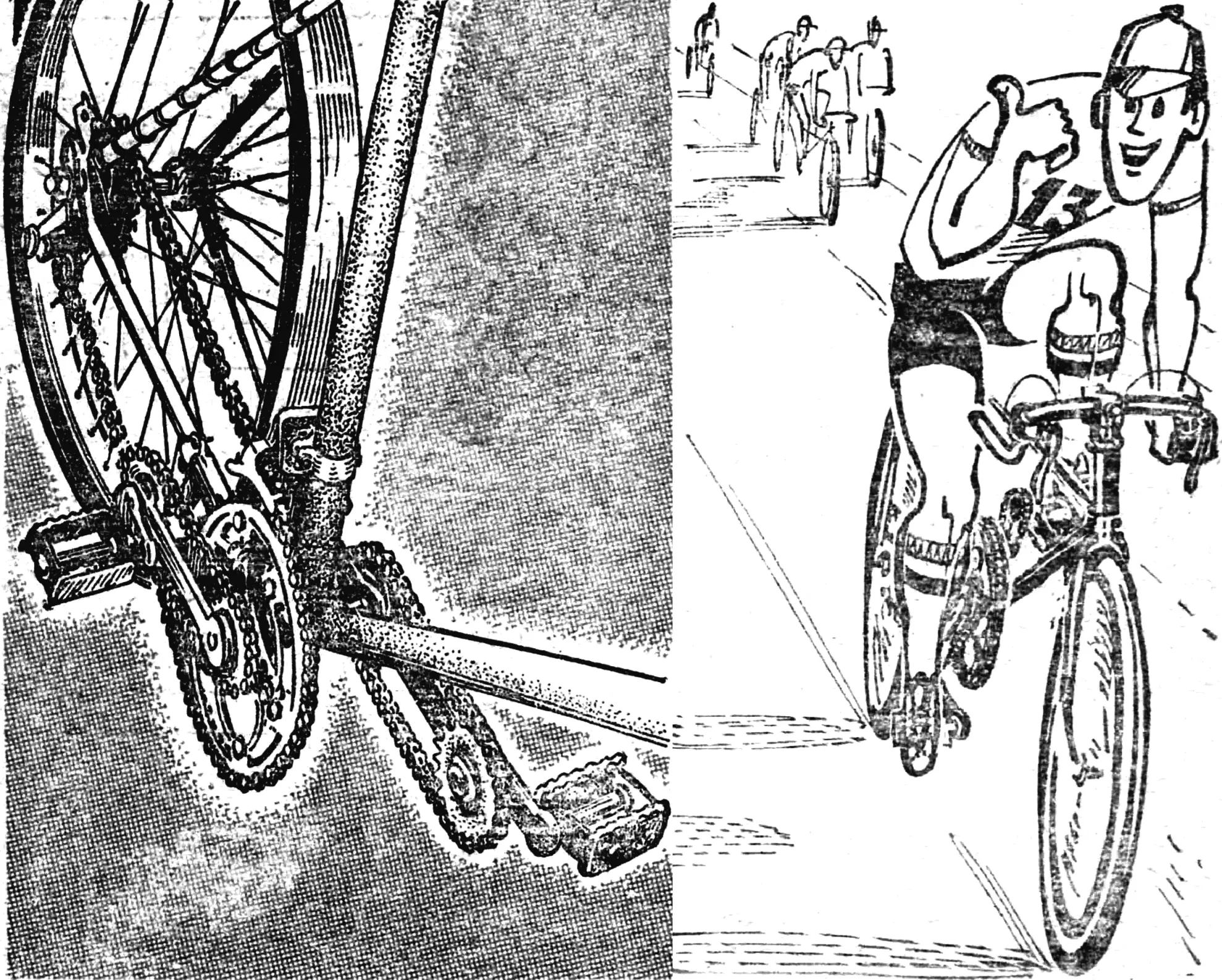
The bicycle is probably the most widespread means of transport. And there is no doubt that it is also the most economical: two buttered sandwiches are enough to pedal for two hours. But can the efficiency of the human “engine” be increased? Reducing “fuel” consumption will not help. Friction and the weight of the machine have already been reduced almost to a minimum. There is also a “gearbox” — a device for changing the gear ratio by shifting the chain onto smaller or larger sprockets. All that remains is to lengthen the pedal levers, but specialists categorically state that their optimal length is 170 mm.
An original solution proposed in recent years has been the elliptical drive sprocket. Readers have already been introduced to this invention in detail. With the help of the ellipse, the gear ratio changes cyclically, better matching the pedal mechanism to the rider, but… without making the work easier.
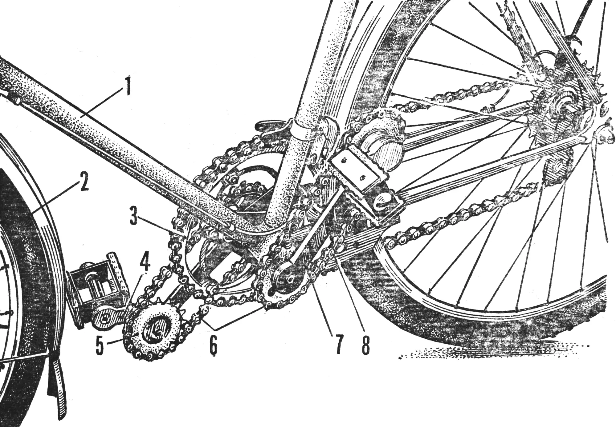
1 — bicycle frame, 2 — front wheel, 3 — drive sprocket, 4 — additional pedal lever, 5 — lever sprocket, 6 — additional chain drives, 7 — crank, 8 — bracket.
In the device offered to the readers’ attention (Fig. 1), it was possible to combine the advantages of an elliptical sprocket and “long” levers: here the torque increases when, under pressure, the unusual levers effectively lengthen while at the same time describing an elliptical curve, although the drive sprocket retains a true circle. In this way a gain in force is achieved and the unevenness of the gear-ratio change is eliminated; the feet describe a circle with the optimal radius — 170 mm.
DESIGN
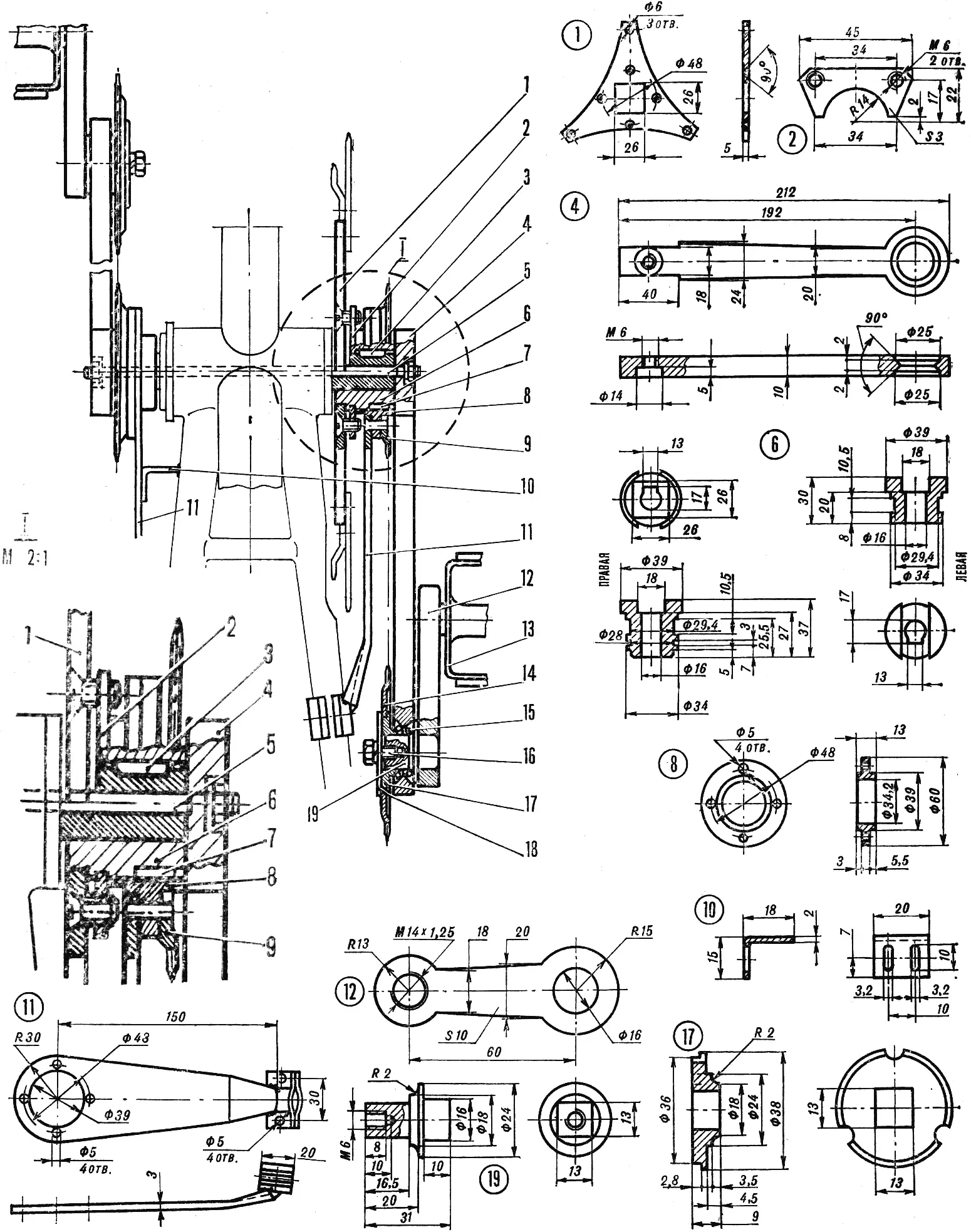
1 — mounting plate of the drive sprocket, 2 — clamp, 3 — key, 4 — main lever (crank), 5 — pin, 6 — bushing, 7 — roller, 8 — bearing bushing, 9, 14 — auxiliary sprockets, 10 — support, 11 — brackets, 12 — extending lever, 13 — pedal, 15 — bearing ball, 16 — bolt, 17 — auxiliary sprocket bushing, 18 — washer, 19 — extending-lever axle.
The pedal mechanism (Fig. 2) also uses the familiar main lever — crank 4, onto whose hub auxiliary sprocket 9 is fitted. It is fixed relative to the bicycle frame — through bracket 11. To the free end of the crank, auxiliary extending lever 12 with pedal 13 is hinged. On the shaft of lever 12, a second auxiliary sprocket 14 is rigidly fixed. Both gear wheels have the same number of teeth and are linked by a chain.
OPERATING PRINCIPLE
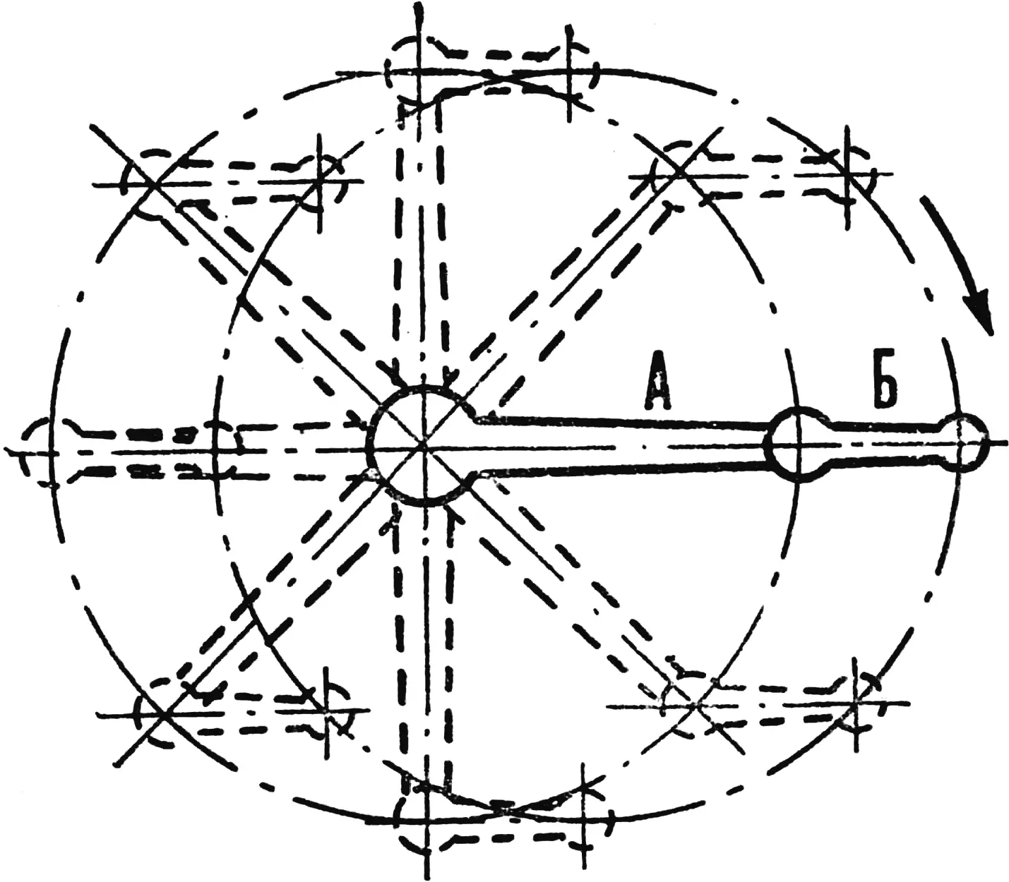
A — main lever, B — extending lever.
When pedal 13 is pressed, the main lever begins to turn; at the same time sprocket 9 (through the chain and the second auxiliary sprocket 14) keeps extending lever 12 always pointing forward and horizontal. The overall path of the extending lever is then an ellipse, in the “front” half of which the greatest radius falls on the pedal, and in the rear half — on the lever hinge. Thanks to this, the forward-extended pedal allows the rider to press it with maximum force precisely on the most effective part of the stroke — from top dead center to bottom dead center, that is, when the main lever effectively lengthens, which provides the gain in force. Although when pedaling the pedals actually describe a true circle with a radius equal to the crank length (the optimal length is 170 mm), they do so shifted forward by the length of the auxiliary lever (Fig. 3).
MANUFACTURE
For simplicity, we will consider the parts in sequence as they are numbered in Figure 2.
Plate 1 is made of decarburized steel 5 mm thick. The drive sprocket of the cranks is bolted to it. Depending on its diameter and the shape of the middle section, the dimensions of the plate’s carrying part are selected (not given on the drawing).
Clamp 2. Two such clamps are made of decarburized steel 3 mm thick. With them the carrying plate is rigidly fastened to the hub of the right main lever — with M6×8 countersunk screws.
Key 3. Two are required, made of steel St45; their dimensions are determined by the cutout in the crank axle and by the size of the keyway in the hub.
Main lever 4. There are two — right and left — made of steel St40Kh. They are joined to their levers (4) by welding. The keyway in the bushings must be on the same side relative to the lever. The hole for pin (5) in the latter is drilled after welding through the bushing.
Pin 5 — of spring steel 65G without additional heat treatment.
Bushing 6. There are two — right (for the right lever) and left (for the left). Material — steel St3.
Roller 7. Rollers Ø 2.4×10.5 mm from an old VAZ-2101 universal joint cross were used.
Bearing bushing 8. Two of steel St40Kh are needed. Four holes Ø 5 mm are drilled in them simultaneously with the holes in auxiliary sprocket 9 and bracket 11.
Auxiliary sprockets 9 and 14. There are four in all. They are standard ones from a rear-wheel hub, with 19 teeth each (sold in bicycle spare-parts shops). On two sprockets (9) the holes are bored out to Ø 39 mm. They may also be made as one piece together with bearing bushing 8 and carrying bushing 17. In that case the number of teeth must not be less than 13. The main (toothless) diameter of such a sprocket is 52.5 mm, and the outer diameter is 60 mm.
Support 10. It is fastened with two M3 screws to the left bracket 11 to provide sufficient forward clearance between the bearing bushing and the hub of the left main lever.
Bracket 11. With their help the auxiliary sprockets are fixed relative to the bicycle frame. They consist of three parts: an arm and two clamps bent to match the frame diameter. The material of both brackets and of the four clamps is decarburized steel 3 mm thick. The clamps are fastened with M5 screws and, after their bend to the frame has been adjusted, are welded on.
Extending lever 12. There are two: both made of steel St40Kh. At one end of each is a pedal hole with an M14 thread, which must be of the matching hand: right-hand on the right lever, left-hand on the left. At the other end is a hole for axle (19); it is welded on. For greater strength, one or two blind holes Ø 4.9×9 mm may be made along the parting line of the axle and lever: before welding, stubs of a steel rod Ø 5 mm are driven into them, acting as a key.
Ball 15. Altogether, 84 balls Ø 3 or Ø 3.2 mm will be needed for the bearings of the extending levers.
Bolt 16. There are two, M6×10 mm — for fixing the sprocket on the lever.
Bushing 17 for the auxiliary sprocket — two pieces — of steel St40Kh. Three peripheral slots are machined to fit the projecting parts of sprocket 14.
Washer 18. Two, of decarburized steel 2 mm thick; the inner and outer diameters are 6.5 mm and 38 mm respectively.
ADDITIONAL RECOMMENDATIONS
To make the device from these drawings it is necessary to have a hollow bottom-bracket axle. An axle with square-taper ends may also be used, but then the holes in the crank hubs must match its dimensions, and the gap between the bicycle bottom-bracket hub and the crank hubs must be at least 1 mm.
The clearance needed for normal rotation of the extending lever relative to the crank is obtained by selecting the thickness of the steel washer (washers) fixed between the axle of extending lever 12 and washer 18.
The center distance of the main and auxiliary levers is approximately 172 mm. To keep the chain from being slack, its size is determined during assembly. How is this done? The extending lever and sprocket are fitted on the free end of the crank. On the bottom-bracket axle the other auxiliary sprocket and bearing bushing 8 are mounted (not finally) on the hub. A 590 mm chain is fitted over both sprockets, tensioned, after which the lever and hub are welded to each other. For dismantling, pin 5 is removed, a screw is screwed into the M6 hole, and with a suitable drift through the hole in the central axle the main lever (crank) is driven out.
A trial assembly is made, before which parts 1, 2, 4, 8, 11, 12 and 17 are heat-treated (carburized). Between the crank and the extending lever, and also between the main lever and the carrying bushing, plastic seals made from a suitable-diameter ring 1 mm thick are inserted.
* * *
The pedal mechanism with automatic lever lengthening has been recognized as an invention and is protected in Bulgaria by an inventor’s certificate. Everyone who has tried the novelty notes not only the constructive originality of the solution to the problem posed, but also the positive effect achieved thanks to it: better “responsiveness” of a bicycle fitted with such a mechanism, easier riding on hard routes, and climbing hills.
“M-K” 7’85, Based on the magazine “Napravi Sam”, People’s Republic of Bulgaria
Recommend to read
 SUGGEST MODELERS ERFURT
It seems that it does not intersect the path of the guys involved in designing the different kinds of models. And competitions are organized separately, and laboratories of its own, Avia... AMPTRAC “OB”
If you try to list all the known constructive scheme of ATVs, that's probably not enough of this page — after all, their number comparable to the number of Amateurs involved in...
