The use of the resonance of the exhaust pipes on the engine all model classes allows us to dramatically improve athletic performance competitions. However, the geometrical parameters of the pipes are determined, usually by trial and error, since to date there is no clear understanding and clear interpretation of the processes occurring in these gas-dynamic devices. But in the few sources of information on this subject are contradictory findings, which have an arbitrary interpretation.
For a detailed study of the processes in the pipes, customized exhaust has created a special installation. It consists of a stand to start the engine, adapter engine — pipe fittings for the selection of static and dynamic pressure, two piezoelectric sensors, two-beam oscilloscope C1-99, the camera, the resonance of the exhaust pipe from the engine R-15 “telescope” and a homemade pipe with black surface and additional insulation.
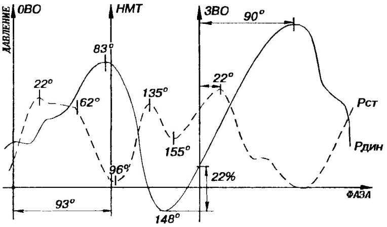
The pressure in the pipes in the area of the exhaust was calculated as follows: motor output at the resonant speed (26000 rpm), the data with attached fittings selection pressure of piezoelectric transducers were displayed on an oscilloscope, a frequency sweep which is synchronized with the engine speed, and the waveform was recorded on a photographic film.
After developing the film in contrast the developer image transferred on tracing paper to scale of the oscilloscope screen. Results for pipe from engine R-15 is shown in figure 1 and a homemade pipe with black and additional insulation in figure 2.
Fig. 1. The change in pressure in the exhaust pipe of the resonant R-15.
Fig. 2. The change of pressure in a homemade insulated exhaust pipe.
On the charts:
R Dean — dynamic pressure, P St static pressure. OVO — opening of the exhaust Windows, BDC — bottom dead point, ZVO — closing exhaust window.
Analysis of the curves allows to identify the distribution of pressure at the inlet of the resonance tubes as a function of the phase of rotation of the crankshaft. The increase in dynamic pressure since the exhaust window with the diameter of the outlet pipe 5 mm occurs on R-15 to approximately 80°. And its minimum is in the range of 50° — 60° from the bottom dead point at the maximum purge. The increase in pressure in the reflected wave (from the minimum) at the moment of closing the exhaust window is about 20% of the maximum value of R . The delay in the action of the reflected wave of the exhaust gas is from 80 to 90°. For static pressure characteristic increase in the range of 22° with a plateau on the chart up to 62° from the opened exhaust window, with a minimum, located 3° from the moment of bottom dead center. Obviously, in the case of using the same exhaust pipe purge oscillations occur in the 3°… 20° after the lower dead point, and not at 30° after opening the exhaust window, as previously thought.
These studies homemade pipe differ from the data of the R-15. The increase in dynamic pressure up to 65° from the opened exhaust window is accompanied by a minimum located at 66° after bottom dead center. This increase in pressure of the reflected wave from the low of around 23%. The delay in the exhaust gas is less than that associated probably with the increase in temperature in a thermally insulated system, and is about 54°. Fluctuations purge marked in 10° after bottom dead center.
When comparing the graphs, you can see that the static pressure in the heat-insulated pipe at the time of closing the exhaust window is less than R-15. However, the dynamic pressure has a maximum of the reflected wave 54 degrees after closing the exhaust window, and the R-15 this maximum is shifted by as much as 90“! The differences are associated with difference in the diameter of the exhaust nozzles: R-15, as already indicated, the diameter is 5 mm, and the insulated — 6.5 mm. in addition, due to the better geometry of the pipe R-15 the coefficient of restitution static pressure her more.
INSIGHTS
Data presented in previously published studies do not give a true picture about the dependence of the static and dynamic pressure from the rotation angles of the crankshaft of the engine and the characteristics of the resonance pipes.
The efficiency of the resonance of the exhaust pipe largely depends on the geometric parameters of the pipe section of the exhaust pipe of the engine, temperature and timing.
The use of controltracea and selection of a temperature mode of resonance of the exhaust pipe would shift the maximum of the reflected pressure waves of the exhaust gases at the closing of the exhaust Windows and thus dramatically increase the effectiveness of its actions.
Insulated exhaust pipe well-chosen geometry give with a simultaneous increase in the engine temperature the dynamic pressure at the moment of closing the exhaust window, which further enhance the power of the engine. For a more complete understanding of such physical quantities, both static and dynamic pressure systems, customized exhaust as well as the impact of temperature regimes can recommend two latest editions of the following references.
V. FONKICH,
O. KUZNETSOV,
Cherkassy,
Ukraine
Recommend to read “THE JANITOR” — ON THE WINDOW Replacing outdated car "janitor", as often called the wiper, attach the handle with extension rod — get a handy household tool for cleaning home Windows. WATER WISELY Debilitating heat, thunderstorms with occasional showers, shallow wells and streams, and ultimately missing the harvest of root crops, dried berry bushes and fruit trees. As is well...