Fig. 2. Single-stage impeller installation:
1 — cook, 2 — BHA, 3 — RK, 4—, 5 — engine.
Fig. 3. Fixture for slotting grooves:
1 — housing (steel) 2 — M5 screw 3 — washer 4 — disc 5 — the risks of pegging, 6 — control of risk.
The impeller blades are made of fiberglass (work piece thickness 1,3—1,5 mm). Twist also produced in the device (see Fig.) the following edge. The workpiece is heated on a hotplate until light brown, then it is placed in the fixture and clamped with pliers. Having sustained a few seconds, the workpiece is removed. It should be noted that glass fiber should not be overheating to the appearance of dark shades and this can lead to delamination of the material. The finished blades is the difference of the angles at their ends must be the same on all parts and equal to 20°. You need to consider in advance that the workpiece blades, and racks RK motor vyrazhaetsya with a stock length 1.5—2 mm.
The production of discs is performed in the following sequence. In the center of the blank sheet of the PCB (by the way, in the absence of the required material thickness of 8 mm blanks can be glued from a set of more subtle. But from the “logs” of the disks to sharpen, as they are not strong enough), cut with a margin on the contour, drilled hole Ø 5 mm In the Chuck of the lathe clamp the metal rod Ø 30 mm, 15 mm protruding from the jaws. His face piercing holes up to Ø 5 mm for a length of 6 mm, after which groove you put on a blank disc and press its center rotating with washer Ø 30 mm. Then proceed to the processing tools. The Central hole in the discs is easier to do after cutting through the slot.
The disk layout. On a sheet of paper is drawn a circle slightly larger than the disk. It is divided into the desired number of parts. Center points is carried out rays. The disk is applied to the drawing, combine the centers and the rays spend risks from the edge to the center of the disk (you should strive for maximum accuracy).
Marked disk is put on the fixture shown in the picture and a hacksaw saw through the slots under the vanes. In ON operation is carried out by a single canvas at a depth of 5 mm, and the drives of Kazakhstan and the motor is dual to a depth of 7 mm. After propilivanija grooves final processing is carried out on a lathe. Are clean the Central hole and outer bevels around the circumference. Then comes the Assembly: profiled blades, the lower ends of which are tipped with sandpaper, lubricated with epoxy and put in the disk. Thus collect ON.
RK first assemble without gluing to control the location of the blades, and then carried out the gluing with epoxy. After curing deformative blades — they should have a PLANO-convex profile with maximum thickness at 1/3 of their chord. Then on the mandrel with a length of 6 mm and Ø 10 mm calibrated outer diameter RK. The disks are mounted stoppers and finally, proceed to the balancing of the RK. The fit ON the diameter of the rings is made by cutting ends of the blades of the scissors on the markup from the center hole.
Additional fixtures. Figure 4 shows a device for the twist of blades RK in progress, or from solid aluminum with a thickness of 1-1,5 mm, or steel. The plates are drilled two holes Ø 3 mm, through which pass screws M3 nuts. However, at steel plates to thread M3, then the nut is not required. The raised plate is clamped in a vise at the lower ends of the screws and twist the package in a clockwise direction at an angle of 20°.
Fig. 4. Fixture length of twist of the blades of Kazakhstan:
1 — plate (steel) 2 — M3 screw, 3 — screw nut.
Device for profiling of the vanes is made of a metal pipe Ø 25-30 mm which is slit, as shown in the figure.
Fig. 5. Device for profiling blades.
The most difficult work on the fixture for cutting the slots in the disks (see Fig.). Its body is made of steel with a thickness of 1-1,5 mm. In each element of the body of the tool — a type of calibration notches. For example, in one kerf at a 45° angle for mounting and Assembly of the RK and at an angle of 10° for the VNA. And the other for the HA1, HA2 and motor. In the recess grooves of the calibration is very important to ensure coincidence of the axes of the grooves, the longitudinal and transverse axes of the hull at one point.
Options impeller installation. Two-stage impeller with a glow motor a working volume of 2.5 cm3 is designed for copies of aircraft of type An-72, An-74, Il-76, Yak-28, Il-20, where the housing model of the installation may perform the functions of simulating scale nacelles. Figure 6 shows a variant of the impeller, which is mounted inside the fuselage of a copy. He has a number of peculiarities: lengthened diffuser carb motor, extension cable set silencer for discharging exhaust gases from the volume of the impeller, in a housing made of an additional window.
Fig. 6. Two-stage impeller with a “pushing” of Kazakhstan:
1 — muffler, 2 — selection of pressure tank, 3 — cone stands Windows, 4 — additional Windows, 5 — diffuser, 6 — mount muffler, 7 — the nozzle.
Given an easier option pseudorational installation. The rotor has one degree, under the same through-sections of the impeller leads to a drop in static thrust to a value of 600 to 700 Gauss. However, such installation is not only simpler, but also easier, which in some cases may be of paramount importance for the forger.
It should be noted that the proposed technology is easy to develop and larger variants of propulsion. Made the impeller under the engine a working volume of 10 cm3 develops a static thrust of about 3 kgf.
The settings of all options is the selection of the angles of the BHA within a small range, and its blades, it is useful to give more in the manufacture of some twist (to the outer ends, the mounting angle is reduced to 3-4°).
Recommend to read THE MOTOCROSS TRACK WITH GOLOPRISTAN The original self-similar route, combining elements of technical creativity, sports competitions and physical training, developed a young technology of the German Democratic Republic.... NEW ROLE TUBE Experienced owner never burn in the kitchen, lifting the hot lid on the stove pots, pans or kettle. To protect hands from this helps her wine tube is threaded under the loop handle on... 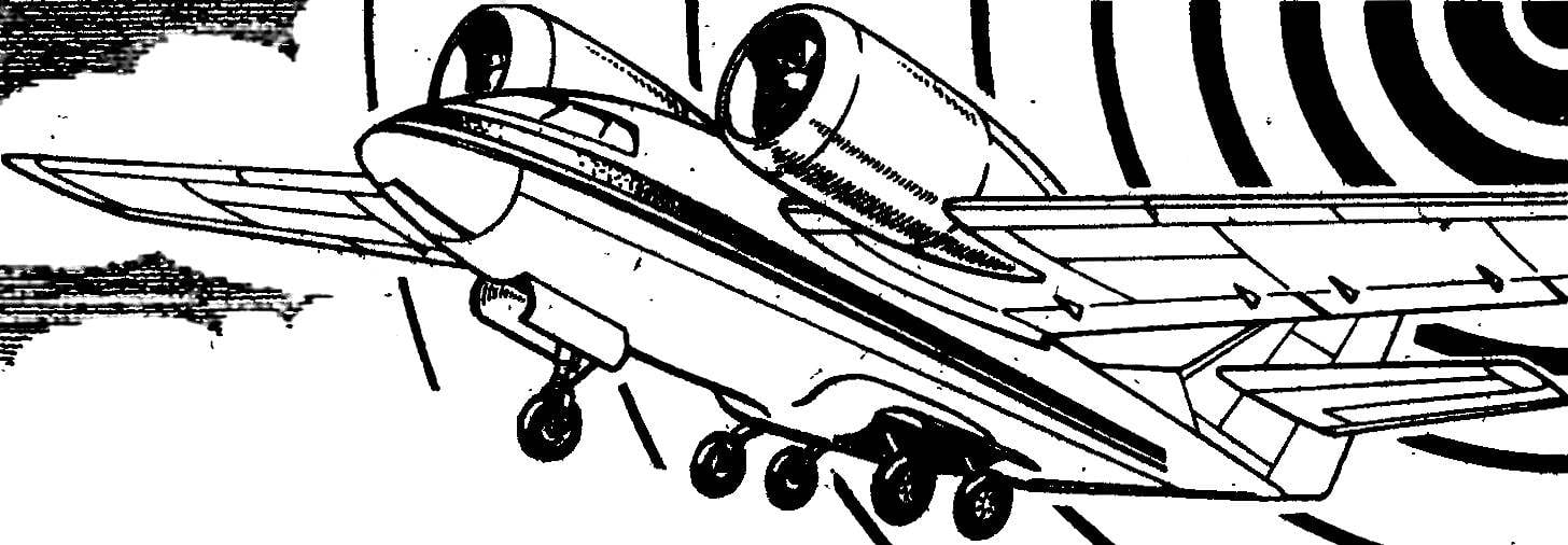
 We can safely say that the interest of model aircraft to jet technology continued unabated ever. Until recently, however, attempts to create flying machines with jet propulsion was only occasional, experimental and research character. Of course, affected by the absence of these turbojet engines in model performance (on the serial production of the isolated supercomplex samples seriously can not speak).