The trailer has a standard ball coupling device is designed for use ball with a diameter of 50 mm.
Body assembled from panels, each of which has a frame of steel angles 30×30 mm and a cladding made of plywood with thickness of 12 mm in the MB screws with nuts. To the bottom are attached to two longitudinal members of timber section 120×30 mm. Mount body to the frame with a hinge, the mating parts of which are welded to the frame and is bolted to the side members; the front part has a locking mechanism that resembles an ordinary latch, which eliminates the tipping during movement.
Trailer with tipping body:
1 — device coupling, 2 — wheel spare, 3 — detent, 4, 7, 10 — body side, 5 — splash shield, 6 — light signal, 8 — valve, 9 coupling, 11 — wheel, 12 of the longitudinal body, 13 — fitting of the lifting device, 14 — tool tray spare wheel, 15 — frame trailer, 16 — hinge body.

A lifting mechanism (A transport position of the body, B — position of the body when unloading):
1 — connecting hose, 2 — fitting of the lifting device, 3 — support platform, 4 — ring, 5 — pneumatic chambers, 6 — case.
Connection diagram of pneumochamber:
1 — camera, 2 — tube screw, 3 — nuts, 4 — washers.
The scheme of fastening of the fitting of the lifting device:
1 — case, 2 — pneumatic chamber, 3 — ring angled, 4 — nut, 5 — washer, 6 — support platform, 7 — fitting of the lifting device, 8 — connecting hose 9 — clamp.
Trailer chassis:
1 — device coupling, 2 — longeron (steel pipe of 40×40), 3 — ear retaining device 4 — joint body, 5 — strut rear, 6 — brace front-wheel, 7 — wheel 8 — cross member rear, 9 — suspension torsion axle, 10 — front cross member, 11 —bolts, nuts and washers attaching front brace, 12 — bolts, nuts and washers mounting bridge 13, 14 — connecting hose clamps.
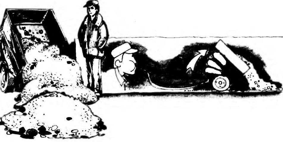
Now about the main thing — the design of the lifting device. It is pneumatic, driven from the exhaust system of the engine. Under the body, between the spars there are three inner tube in case of durable fabric is canvas or synthetic canvas, attached with M5 screws to the rings of a steel angle on the underside and on the frame. All the cameras are connected by threaded connections, nuts, gaskets and washers, and screwed to the bottom fitting, curved in the form of the letter “L” which is a rubber hose. To raise the body, you need the second hose end to put on the exhaust pipe of a vehicle towing and “add gas”. Two or three minutes — and the body will rise. To lower the body enough to remove the hose from the exhaust pipe.
I. KHOROSHEVSKAYA,
engineer
Recommend to read
 “PIRATE”IS A LOSER
Fighter VOUGHT F6U PIRAT. The appearance at the end of the war, military jet aircraft in Germany and Japan forced the command of the naval forces of the United States to start a program... “DONKEY” ASKS THE CAMPAIGN
UNIVERSAL TROLLEY FOR TOURISTS-WATER-TRANSPORT WORKERS. Over the years Hobbies boating, we tested several variants of trucks for transportation of kayak and equipment. And the hikes have...
 Trailers for passenger cars, turning them into a small truck, particularly popular with rural residents and owners of summer cottages. Naturally they greatly facilitate the delivery of a wide variety of goods — sand and peat, sand and manure, bricks and gravel. It is a pity that load and unload their accounts entirely by hand — with a shovel.
