Tires will go even those who are not surfacing, but without through holes. Many hunters had themselves previously cut from felt wads for shotgun cartridges. So, similar to pererobka mill for a long time became my main instrument. To insert the cutter directly into the drill instead of the cartridge, made with a cone (working with the mill-pererobki, clamped in the Chuck of a drill, get tired faster). The sizes of the cutters took an arbitrary and imprisoned just included the emery wheel and brought to him rotating in the drill cutters.
The amount of detail of the tread on the wheel is such that it is not allowed to “thin out” through one without breaking the balance. So, marking them with chalk, did one cut — one left, two cut — one left to continue in the same sequence. And in “Christmas trees” boss of lugs disposed at its sole discretion. Prior to milling was inserted into the tire chamber and pumped. It is better felt layer between the tread and the cord, although sometimes exciting and kordovye thread, but frame — megaloi-
and these flaws on the strength of the tyre is not affected. (There is another, more simple technology, with the tires just peel the rubber to the cord, but then lose the most valuable — powerful of lugs on the lid.)
Received the tires I use all year round, and their strengths and durability evaluated during three years of operation. My friends are craftsmen, too, have made these tires and was very happy. It’s certainly not a revolution in the manufacture of the tires, but already some progress. After all, our industry does not unfold with the production of tires for snowmobiles, and imported most smodels-cov can’t afford it.
With the installation of such tires on the wheels, no need for the longitudinal and transverse straps, and most importantly, the bolts, the number of which is determined almost by the bucket at the equipment of the vehicle chamber tires.
Wheel made with a collapsible rim, combining them from automobile and motorcycle. For each wheel on the guillotine of steel sheet of thickness 2 mm strip cut size mm 1430×330 and bent it on the rollers in the cylinder. “Izhevsk” wheel 18″ freed from the spokes and the rim cut with a angle grinder along. With the halves of the rims of the sides removed the holes and recesses for the spokes nipples. On each side was left with nine petals. On one side put the cylinder, leaving the petals inside, and pulled off his wire. Petals as joint sheet of cylinder, provari, pre-fit edge “grinder.” In the petals of the second side drilled hole with a diameter of 5 mm, and put it on the cylinder with the petals outwards, and the holes in the latter drilled the appropriate holes with a diameter of 4.2 mm in the wall of the cylinder, and removing the Borg, cut them, thread M5. The wheel I used the discs 15″ (from the “Moskvich-402” or “407”), previously them a bit easier.
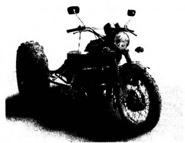
The layout of the tricycle-air suspension:
1 — motorcycle “IZH-Jupiter”; 2 — left arc security; 3 — sub-frame; 4 — sprocket with hub (z = 18, from the wheel of the motorcycle “IZH-56”); 5 — drive chain (t = 19,05); 6 — pneumatic (modified tire of the car GAZ-66); 7 — rear axle (from the car “Moskvich-402”); 8 — casing of the driven sprocket. On the side view of the left wheel with the hub conventionally not shown
Additional frame and rear axle:
1,5—arc security (steel chrome pipe 34×3); 2 — connector bracket (STZ): 3 — cheek with the boss (STZ, the sheet s8, 2); 4 — clips (STZ, 12 PCs); 6 — detachable clip (steel, sheet 15, 2 items); 7 — brace (chrome steel pipe 27×2,5, L505, 2); 8 — spar (stainless steel, pipe 34×4, L1400, 2); 9— pull the passenger pegs (chrome steel pipe 27×2,5, 2); 10 — thrust absorber (steel chrome pipe 27×2,5, 2); 11 — spacer (steel, pipe 27×2,5); 12 — seat thrust (steel chrome pipe 27×2,5, L320, 2 PCs.); 13 — docking station; 14 — rear axle; 15 — casing, driven sprocket (steel, sheet B2); 16 — Boo and a gel farmhouse (steel, sheet 58); 17 — spring strut (steel chrome pipe 27×2,5, 2 PCs.)
Detachable bracket mounting spar
Mount arcs of safety to the frame of the bike:
1,6 — arcs of safety; 2 — the clip on the fog light (2 PCs); 3 — screw M10 (2 PCs); 4 — connector to bracket; 5 — a clamp of fastening of a sound signal (2); 7 — clamp mounting brace (2 pieces); 8 — socket mounting bracket side rail (2 PCs); 9 — cheek with the boss (2); 10 — bolt M10 split washer engine mount (2 PCs); 11 — fog lamp (2 PCs.); 12 — beeper (2 PCs)
Using a drill and a file”; (no longer use) to each disc in the middle of the rims has chosen four of the “window” without affecting the planting shelves for tyres 15″ (disk in the work can be changed). Mindful of the design left on the disc the attachment of the decorative caps to ground wheels they are not particularly affected, but with chrome hubcaps and rims rollers look beautiful.
Then from sheet metal of 3 mm thickness was cut down to eight plates on each wheel for the spacers. Their height — 38 mm (half the difference between the 18″ and 15″), and the length corresponds to the width of the rim “moskovichevskoe” drive. Plate before welding drove around the perimeter under the same dimensions in the package on the milling machine. With a angle grinder with a cutting disc with a thickness of 3 mm at the rim “moskovichevskoe” wheels made eight cuts (not touching the rim size 15″), put them in the prepared spacers and tack welded. Securing the disk on the axis of the axle and rotating it, adjusting the position of the plates and welded them permanently. Modified drive and put in the manufactured rim on the 18” and welded spacers to the cylinder. (As it turned out, it was made prematurely: the design of the bridge is such that by shifting the disk in the cylinder of the rim to achieve the symmetrical arrangement of the wheels relative to the longitudinal axis of the motorcycle.)
Then lightweight bus with a camera put on the cylinder and it also screws M5 attached to the other rim (the screw heads the inside have no influence on the camera).
The camera missed the nipple in the drilled hole in the cylinder and pumped the chamber. The pressure should be such that the camera put side tires on the motorcycle side. Tight fit is guaranteed their identical size and the tire to the rim will not crank. My wheels in operation for more than three years and no trouble until delivered, unlike the previous chamber, which is constantly about yourself resembled. (If any of the readers of the magazine will complement this technology, I’ll be happy.)
To connect the rear axle with the bike made the extra two-spar frame made of inch stainless steel tubing. Their rear ends arched by bending at the rim-relevant cov. (If the ability or desire to bend pipes-no spars, you can use them straight. But then the width of the arcs security will fit under the width of the bracket on the rear axle. This variant is easier to manufacture, but appearance is another.) The front ends of the side members with a special detachable bracket is connected with arcs of security, and recorded their position relative to the motorcycle tie-rods-struts in several points.
Tip n seat post axis
Thrust lugs and lock nut:
1, the lower ferrule; 2 — thrust; 3 — locknut M20x1,5 (24); 4 — top tip
The bit with the brace:
1 — tip; 2 — brace
The tip spar:
1 — tip; 2 — spar
Chain transmission with differential:
1 — wheel hub of the motorcycle “IZH-56”; 2 — sprocket (z = 18; t = 19,05); 3 — axis of the rear wheel of a motorcycle; 4 — axis drive prices; 5 — driven sprocket (z = 56, t — 19,05); 6 — pinion gear; 7 — case; 8 — axle housing
Suspension strut:
1,3 — tip; 2 — pipe
Wheel Pneumatics:
1,4 — half of the rim (of the wheel of the motorcycle “IZH”); 2 — M5 screw (9 PCs.); 3 — the cylinder of the rim (steel, sheet s1,5); 5 — disc (the wheel of the car “Moskvich-402”); 6 — proshivka (steel, plate s, 8 PCs.)
Mill for processing rubber
As arcs of safety to perfectly fit into the design of the pneumatic chrome headboards. Both backs were cut in half. The upper ends of the halves attached by means of detachable bracket mounted on the front tube of the frame of the motorcycle, and the bottom mounted lugs, screwed into a homemade 8-mm steel plate engine mounts. Before installation on the frame of the halves of the arcs of the security for each put on three clamps, one of which hung the fog light, and another audio signal. A third clamp is required for docking of the arc security tube-strut connecting in another location the frame of the bike and an arc of safety.
Protective cover, driven sprocket:
1 — chain (t= 19,05); 2 — sprocket driven; 3 — a protective casing (steel, sheet s2); 4 — rear axle beam; 5 — axis; 6 — the cap of the rear axle housing
Additional fixing of rear axle yoke farm:
1 —the axle housing (“stocking”); 2 — a casing, driven sprocket; 3 — the cap of the axle housing; 4 — oil filler tube; 5 — rope farmhouse
A connecting node of the rear axle and an extra frame:
1 — rear axle; 2 — step ladder (from the springs of the car “Moskvich-402”); 3 — shaft; 4 — a lining of wood (oak); 5 — shaped plate of the bridge; 6 — the host-based (steel, channel No. 12); 7 — nut M10 (4 PCs); 8 — tension screw M20x1.5; 9— resistant stem nut M20x1,5; 10 — spar additional frame; 11, the fixed half of the clamp (steel, sheet s20); 12 — movable half of the clamp (steel; sheet s20); 13 — M10 screw (2 pieces)
Arc security the top is secured on the bracket mounted on the front tube of the frame of the bike under the gas tank. For the manufacture of a bracket of steel with a thickness of 24 mm offreserve the front bracket. On lathe, machined on both sides of the cylinder with a diameter of 28.2 mm (internal tube diameter of the arc security tolerance to interference). To facilitate bracket made drill bit with a diameter of 17 mm blind holes in the cylinder. In the middle of staples performed a semi-circular indentation with a radius of 20 mm, and on the sides of the hole with a diameter of 10 mm. Rear bracket shaped, semi-circular with the same inner radius and the threaded holes M10 on the “feet”. Shackle bow tube of the frame and tightened with two screws M10. The cylinder was press on the pipe arcs security.
The place already drilled the holes in the pipes and tips. Tapped M6 and fixed parts and two screws. Front bracket front bracket and the screw heads are chrome plated.
Arc at the bottom fixed on the bosses of the cheeks assembling the engine. Cheeks cut out of 8mm steel. Then machined lugs, the outer diameter of which also corresponds to the inner diameter of the pipe with a tolerance to interference. Tapped M20x1,5 and machined the end bosses, and drilled holes in the cheeks, hard boiled first to second and press on the tube to the boss.
But Doug had a motorcycle does not offer the reliability and rigidity, which is necessary for mounting additional frame and tension the drive chain of the vehicle. Therefore, the arc is additionally tied to the frame of the bike. To do this from under the seat turned the regular bolt thrust side of the trailer and in its place inserted the axle with two home-made tips at the ends.
From them to the clamps, pre-installed on the arcs, had two brace of the bed of pipe with a diameter of 27 mm with lugs. Initially, all the bits in the pipe was pressed, but during the work it became clear that it is better to put them on the thread, plus in the future, all parts subject to disassembly for chromium.
For the manufacture of rods and racks of the frame-consoles almost everywhere used pipe with a diameter of 27 mm og those bed backrests. They are chrome and look good. However, have holes in the walls, but during Assembly thrust set so that the hole was hidden from sight.
The pipe struts tapped M20x1,5 at a depth of 25 mm. are also manufactured and thrust, but they installed the lugs with locking nuts M20x1,5 for the key 24, which is made of inner groove with a diameter of 27 to a depth of 5 mm.
Tips to alleviate them drilled blind holes with a diameter of 14 mm. So as not to confuse the connector during Assembly of the vehicle, tried to unify them. (If possible, desirable to make one side of the joint on the right, and the other with left-hand thread that will provide the best adjustment of the console relative to the motorcycle.)
The dimensions of the rods, shown in the figures, a reference, as in the course of their Assembly will fit in place.
For this vehicle I used the rear axle of the “Moskvich-402” without brake drums. Removed from the case main gearbox and with a angle grinder sawed off from the housing the mounting location of the “shank” of the driving gear. Most helical bevel gear let go of the horn and grind her back side under the diameter and thickness of the sprockets with number of teeth 56 and pitch of 19,05 mm. In asterisk drilled the appropriate holes and use regular bolts to put her on modified gear.
Previously the building, which siteplan differential, sawed the “grinder” along, providing the sprocket free rotation. Differential and axle shafts retained.
Outlining on the axle housing place of the asterisk, it also cut across the “grinder.” Here cut another strip width of 40 mm, in order subsequently does not cling to the body.
The bridge then collected, atcentral and pre-scalded with four reinforcing rods for the device there is a protective cover stars. This cardboard made two stencil, one repeats the outer profile of the axle housing section, the other on the outer diameter of the sprocket with the height of the chain and a small gap. Front casing is made ledges, maybe later I’ll make a chain of rubber tubing. Of steel 2 mm thick stencil cut out two parts and took them to the body of the bridge. At the outer contour of the two parts joined by a metal strip.
Before finally boil, make sure the alignment of the side casings (“stockings”). For greater reliability the underside of the bridge was welded on another farm rope of 5-mm steel. The bridge turned out not so heavy, but solid enough.
For the manufacture of the hub under driving sprocket I took the old “Izhevsk” wheel and cut on a lathe all the excess, leaving only the brake drum. On the sprocket g = 18 wasted inner hole for the pipe hub, planted one on another and welded.
Since the hub was used from the Property the old model had between it and the housing rear wheel drive to install axle washers as the length of the splines it is smaller and the hub is pressed against (present-day wheel types it is better to use a native hub; on a lathe to “liberate” it from spicely holes, and the metal bearing housing to weld the sprocket).
Brakes kept regular. I would like to warn: the spinning wheel of such large diameter have considerable inertia, so it is impossible to brake sharply on the chain, sprockets, differential and axle shaft when it transmits large loads, which can lead to their failure.
For the same reason, upon compression of the shock absorbers sometimes slips the chain. So, instead of shock absorbers I installed two spacers of the same Nickel-plated tube and rod. Sleeve the tip is pressed into the pipe.
To connect the rear axle with an auxiliary frame motorcycle manufactured two docking ports. The basis of each node is the interval channel number 12. One side connected it with two M10 bolts with welded to the bridge of the profiled plate to which on “Muscovite” is attached to the spring. The second party associated with the shroud bridge “moskovichevskoe” spring step ladders draped over “stocking”.
Between the channel and “stocking” set a strip of solid wood to the bridge axis and the middle line of the channel are parallel. In the regiments of steel channel drilled hole: front — under the diameter of the pipe member, the rear under tensioning the bolt. At completion of the bridge asterisk was installed with offset to the left from the middle of the bridge is approximately 30 mm. AU distance I have taken into account in the manufacture of parts of channels: to preserve the symmetry of the wheels left the item did 30 mm longer than the right. At the same distance to the middle has shifted and the holes in the shelves left of the part. The position of the wheels could be adjusted by displacement of the disc in the rim. I hastened to the weld, and this adjustment I had to make washers for the hubs.
In the event of rupture of the drive chain rear axle remained on the pipe-rail consoles, a specially made detachable bracket with a hole for the pipe diameter. The lower half of the bracket with the screw holes welded from the outside to the shelf channel. After the chain pulling the M10 bolts are tightened and the bracket their jaws squeezes the tube-spar, connecting the bike and the console as a single structure.
Under the front wheel installed removable ski (describing its various variants have been published in the “Modeller-designer”), Deep soft snow my suspension, of course, the barrier — affects the weight of the motorcycle. His element — dense snow and off-road.
V. BARANOV, Novosibirsk, Russia
Recommend to read FLASHLIGHT-IMPROMPTU Flashlight-impromptu can be made from storage battery and a bright led. The battery is installed between the findings of the led, observing polarity, and fasten a large sandbox or... MOTOBLOCK WITH A TWIST I am a reader of "Modeller-designer" for nearly three decades and twenty-five years engaged in technical creativity. Over the years, made a lot of homemade designs, including presented...