
 Probably, many motorists familiar with this situation: after a continuous drive for a distance of 200 — 300 km of the right leg begins to resemble what it is and what it is time for her to relax. Although it is necessary to go for a long time. For the rest of the legs during long trips propose to install in the car simple device. Conventionally, I called it “autopilot”, as it was able to maintain the set speed when driving on a flat road. Moreover, in the case of the overtaking allows you to add “gas” and then again remove the foot off the pedal the vehicle will continue moving with the same pre-set speed. Turned off the device instantly, you only slightly press the brake pedal.
The design of “autopilot” is simple. Almost all of its parts are made of sheet steel. The electromagnet picked up ready — stamps is-1841. True, I had to redo it.
Instead of one coil, designed for the 127, I wrapped two: the launcher and restraint. Launcher has 700 turns of wire sew-2 diameter of 0.4 mm, holding 2,000 turns of wire sew-2 diameter of 0.25 mm.
After manufacture of all parts began to assemble (Fig.1). First to the body of the electromagnet 1 welded bar 2 (through the Central hole 6 mm in diameter; and so that the melt was not made by him). Then to the base 3 welded corner bracket 7 and the shim 12. At last, using the bar as a template, made through holes with M4 thread. Installed the solenoid and fit in place the spacer 11 (it must be tight, no gap), welded it to the corner bracket. Installed in place of the l-shaped arm 8.
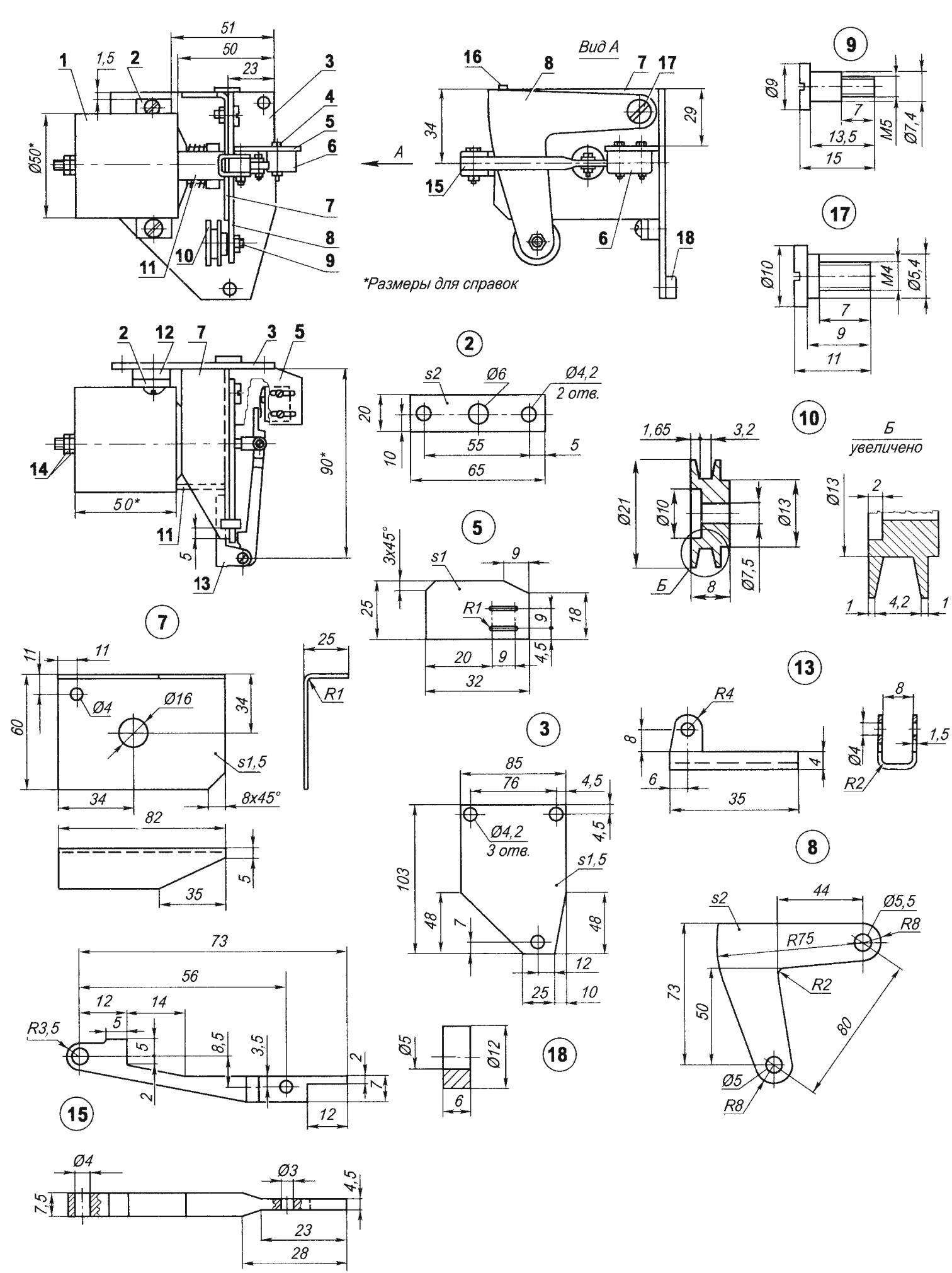
Fig. 1. Device to maintain the desired speed of the car:
1 — solenoid (EC-1841); 2 — lath; 3 — base; 4 — fixing screw microswitch (2); 5 — shelf mounting micro-switch; 6 —the switch (MP-2); 7 — bracket; 8 — l-shaped arm; 9 — the screw-axis of the unit; 10 — the block (bronze); 11 — spacer (sheet s1,5,25,5×10); 12 — a lining (sheet s4,65×20); 13 — bracket clamping arm; 14 — adjusting nut; 15 — clamping lever; 16 — focus (sheet s1, 8×5); 17 — the screw-axis G-shaped lever; 18 — Bush
The inner end of the clamping lever 15 by a screw attached to the plug magnet, and the outer end to the bracket 13 of the clamping lever, which is then welded in place to the corner bracket. After that, the shelf 5 and a switch 6 attached by welding to the base and the corner bracket so that the axis of symmetry of the clamping lever coincides with the axis of the microswitch. And lastly welded the stop 16 (corner bracket) and sleeve 18 (to the base). This sequence of operations to ensure accurate Assembly and almost ruled out the fit of parts.
Rotation of adjustment nuts electromagnet has achieved the minimum clearances, in which an l-shaped lever moves between the corner bracket and the clamping lever without friction. Further, by releasing the core of the electromagnet, move the microswitch to the clamping lever so that it worked; in this position and tightened the screws of its fastening. The microswitch has a full-time spring record without it clamping lever gradually break the button because the buttons are minor and difficult to accurately set the time of deployment. This Assembly and adjustment of the device is finished.
The device is placed under the hood of the car. The lever of a drive throttle valves of the carburetor drilled two holes and screwed the lever-plate. Of course, it is easier to weld the plate, but when I collected the device, it may not know how it is working, so did everything so that if necessary it can be easily removed.
Then put the device to the bulkhead of the engine compartment (the wiring harness that runs along the wall, got up and laid on the angle bracket), combined bronze block (Fig. 1, POS. 10) with a lever-plate and drilled in the wall with three mounting holes as the upper bolt M4 bottom — screw-a screw with a diameter of 4 mm. Attached the device and checked how it works. With a tap of the throttle (lever-pad in this case backwards) of the l-shaped lever was easily under its own weight to fall, and the bronze block to slide on the lever-plate and does not disengage with him. When the pedal is released, the l-shaped lever was smoothly return to its original position.
Having thus a mechanical part of the device, I started the installation of the electrical part. The button SB1 is used to activate the device, and put it in the cabin. Microswitch K1.1 established under the brake pedal so that when slightly pressed pedal of its normally closed contacts open. Microswitch K1.2, remember, is on the shelf device. Then connected all the wires according to the schematic wiring diagram.
When everything was connected, started the final inspection of the device. Pressing the pedal “gas”, included SB1 and a second later he let go of her. During this time, the electromagnet pulled the core and took clamping lever from the microswitch K1.2, the contacts which took over the power to the electromagnet. When the solenoid the throttle must remain in a fixed position. If she “goes”, it is necessary to readjust the clearance between l-shaped and the clamping levers. Does not help— pound rosin and pour it into this gap. By pressing lightly on the brake pedal, the solenoid should be turned off.
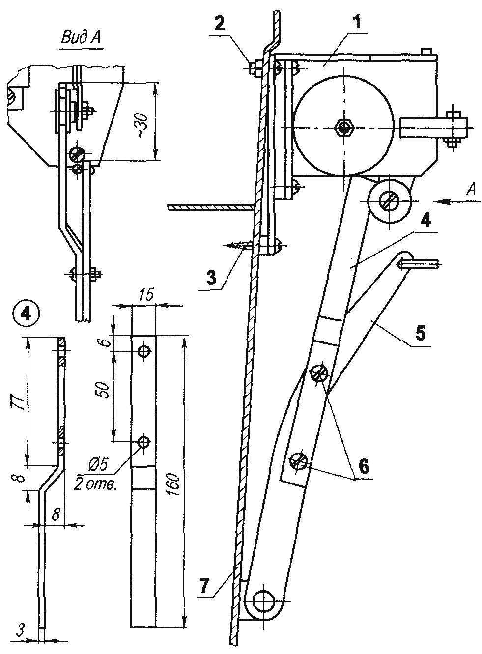
Fig. 2. The arrangement of the device under the hood of the car:
1 — device; 2 — bolt М4х10 (2); 3 — self-tapping screw Ø4; 4 — arm-cover plate; 5 — the lever of a drive throttle valves of the carburetor; 6 — M4 screws; 7 — partition of the engine compartment
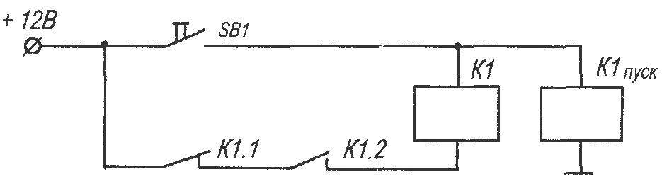
Fig. 3. Schematic wiring diagram:
K1 start — starting winding of the electromagnet; K1 —the hold-in winding of the electromagnet; K1.1 — microswitch at the brake pedal; K1.2 — micro-switch device; SB1 —button in the cabin (KM-1-1)
Now about how I use the device. When my “Zhiguli” VAZ-2102 acceleration and attains the desired speed, for some time, fix the throttle to the speed stabilized. Then press the SB1 button and remove your foot from the pedal, then the car is driven on “autopilot” — at a set rate. On a level road and the engine well regulated, it almost does not change. On the dashboard of my “two” is econometr. So, the position of his hands is seen: if after switching on the device and take your foot off the pedal “gas” arrow remained in the same position, so the car is driving at a given speed. In order to disable this mode, lightly tap on the brake pedal.
It happened that from shaking on rough roads the device would shut off due to the fact that the brake pedal swings pushed the button SB1. After adjustment of the microswitch at a later triggering a spontaneous shutdown stopped. Other defects in eight years of operation of the device was observed.
Use their “autopilot” in the city and in the warmer time of the year when the pavement is dry and clean. In winter, turn it on very rarely, as, for example, when skidding, the driver is “programmed” to remove the foot off the throttle, not the brakes. Therefore, it is better not to risk it.
I should add that although this device is designed for VAZ-2102, it seems to me that something like this can be installed on other models of cars.
V. SAINOV, Severodvinsk, Arkhangelsk region.
Recommend to read
 SHIPS ON THE LINE
Far from the flares in Europe, the war, even the Americans in 1940 still did not think about creating your own escort destroyers. They continued to build its "big fleet", which included... HONDA CIVIC
The Japanese company Honda Motor every four years, represents a radical new family car HONDA CIVIC, IN September 1995, the firm unveiled at the IAA'95 the sixth generation of these cars...
