“POLITBURO” – THE LOCOMOTIVE OF KOLOMNA

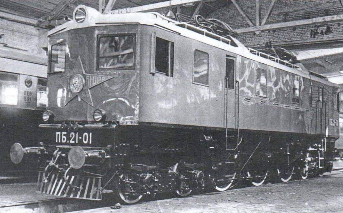
Locomotive PB-21 of issue, 1934. In the early 1930-ies the USSR had embarked on the reconstruction of Railways, in particular, the decision not to build cars with the number of axes less than four. Rolling stock was assumed to be equipped with automatic couplers and air brakes automatic. For the traction was designed and built powerful locomotives – freight and passenger FD IP. It was planned and the electrification of the Railways; it was built Сс11 electric locomotives, cargo and passenger vehicles ВЛ19. In addition, the Central lokomotivostroenie Bureau (CLPB) together with the plant “Dinamo” has designed a locomotive designed for pure passenger services. It was a very original car, not like any one of the locomotives of the time. Moreover, this engine was absolutely unique – a hitherto nothing of the kind in our country were not built.

Unlike other domestic electric, the body of the locomotive rested on a huge, the entire length of the body, stick frame. In the middle of the frame were set three pair of wheels with a huge diameter 1850 mm driving wheels. Front and back of them was one two-axle truck with begunkova (without drive) wheels. The chassis of the locomotive, therefore, was the same locomotive with the axial formula 2-S0-2. Designed by the specialists of the Kolomna plant under the leadership of engineer A. E. Lobko.
Each drive axle had a motor drive, DSA-680/2. Engine designation stood for “dual Motor locomotive with a capacity of 680 kW”. It was called dual because structurally consisted of two engines, DPI-340, connected by bolts. From the engines, DPI-340, is applied on electric locomotives and Сс11 ВЛ19, they are distinguished by mutated skeletons. This twin-engine bottom joined motormouse axle box bearings, which revolved around the pair of wheels, a hollow shaft, through which was passed the axis of the wheelset. Both of the motor shaft, DSA-680/2 through gear drives the rotation of the hollow shaft. The latter, in turn, via the spring-jaw clutch design AEG drives the rotation of the wheel pair. Pruinocarpa coupling is required to compensate for the displacement of the wheel axle relative to the traction motor, as here the engine, unlike the electric locomotives Сс11 and ВЛ19, relied not on the axis of the wheelset, and mounted on the frame of the locomotive being completely sprung. Such design allowed to significantly reduce unsprung mass, thus making the progress of the locomotive more smoothly.
 
Original suspension and traction motors were not the only features of the new locomotive. All axlebox nodes mounted spherical roller bearings. By the way, the next attempt of modernization in axle-box assemblies of the locomotives will be made after twenty years.
 
The locomotive Pennsylvania W P5.d. (USA) - a possible prototype of the electric locomotive ПБ21
 
The locomotive Pennsylvania W P5.d. (USA) – a possible prototype of the electric locomotive ПБ21
 
In addition, the new locomotive is equipped with two so-called mechanical compressor single-cylinder machine driven cranks mounted on the ends of the driving axles via the connecting rods and balance weights. The use of such compressors should have excluded the situation where the locomotive is when the voltage in the contact network will not be able to provide the brakes with compressed air will be their exhaustion.
 
Amid all these design innovations no longer seem strange and the name of the locomotive. The fact that at that time all new locomotives were designated according to the nomenclature of 1931, according to which the literal part was the initials of one of the party or the Soviet leaders, and digital axle load of the locomotive in tons. It was so named steam locomotives ФД20 (“Felix Dzerzhinsky”), IS20 (“Joseph Stalin”), electric BJ119 (“Vladimir Lenin”), and the alphabetic part in a series of new electric locomotive ПБ21 hid not one any person, and all (!) Politburo of the Central Committee of the CPSU(b) from.
 
A possible prototype for this locomotive could become American locomotive R-5, built in 1930 for the Pennsylvania railroad he had the same axial formula and the same drive in which each wheel set is driven by dual-motor. This, however, was the only common features of electric R-5 and ПБ21. So ПБ21 can be regarded as a copy of the American locomotive, but rather “a fantasy”.
 
Electrical ПБ21 did not differ from that installed on electric locomotives and Сс11 ВЛ19. The current collection from contact wires provide the same current collectors of the type J-4, and protection of power circuits was carried out the same high-speed switch BVP-1A. As the locomotive ВЛ19, dual fan has rotated with an dynamotion DD-60, however, unlike ВЛ19 through the propeller shaft, and compressed air for pneumatic equipment is provided from the compressor CZB-6. Similarly freight brethren, ПБ21 locomotive was equipped with a system of many units to work double thrust. System this locomotive is not suitable, since ПБ21 released in a single copy. To work together he was just with.
 
General view of the locomotive ПБ21
 
General view of the locomotive ПБ21
 
General view of the locomotive ПБ21:
 
1 – trolley J-4; 2 – horn; 3 – nameplate of the plant “Dynamo”; 4 – the buffer lantern PB-24; 5 – outlet bielectronic compounds; 6 – paleocortical; 7 – begunkova pair of wheels; 8 – begunkova truck; 9 – plate Kolomna plant; 10 – sand injector; 11 – sand pipe; 12-axial compressor; 13 – brake lever transmission; 14-spring; 15-sand bunkers; 16 – balancer for suspension; 17 – the driving pair of wheels; 18 – driving axlebox node of the pair of wheels; 19 – brake cylinder; 20 – axle equipment wheelset begunkova; 21 – support the body begunkova cart; 22 – main tank; 23 – the buffers; 24 – headlight; 25 – end sleeve nourishing highway; 26 – screw coupling; 27 – end sleeve brake line
 
Location of equipment in the locomotive ПБ21
 
The arrangement of the equipment in the locomotive ПБ21:
 
1 – paleocortical; 2 – limit sleeve of the brake lines; 3 – buffer; 4 – socket inter-locomotive connections; 5 – buffer lantern PB-24; 6 – floodlight; 7 – collector J-4; 8 – horn; 9 – end sleeve nourishing line; 10 – dashboard; 11 – valve of the auxiliary brake; 12 – the independent; 13 – driver controller; 14 – driver’s seat; 15 – electric furnace 2 of the second group; 16 – front high-voltage cell; 17 – compressor С2В-6; 18 – sand bunker; 19 – pushtorsky resistance; 20 – motor-compressor CPM-300/4A; 21 – fan traction motors; 22 – dynamotor DD-60; 23 generator control DU-3; 24 – the valve of the susceptor; 25 – battery 26 – high voltage rear camera; 27 – high-speed switch BVP-1 A; 28 – chair assistant driver; 29 – electric oven 1-group; 30 – begunkova pair of wheels; 31 – axlebox node of begunkova wheelset; 32 – spring suspension begunkova truck; 33 – begunkova truck; 34 – bearing body begunkova truck; 35 – electro-pneumatic contactors; 36 – sand pipe; 37 – driving axlebox node of the pair of wheels; 38 – sand injector; 39 – brake lever transmission; 40 – spring coupling AED; 41 traction motor, DSA-680/2; 42 – housing of the traction reducer; 43 Bush of the motor-axial bearing; 44 is a driving pair of wheels; 45 – brake cylinder; 46 – inductive shunt; 47 – control panel; 48 – main tank
 
The scheme of the locomotive allowed it to operate in traction mode in three connections of traction motors. In addition, ПБ21 was equipped with an electric braking system, but not regenerative mounted on Сс11 and BJ119-01, and a rheostat in which the traction motors operate in the generator mode, however, the electricity generated by them is not returned in the contact network, and “burned” at the starting resistors, which in our days are called pushtorsky. This is wasteful, but safe, because rheostatic braking can be used even when there is no voltage in the contact system when recovery is impossible.
 
Rheostatic braking of electric locomotive ПБ21 was performed according to the original scheme with cyclic stabilization, developed by engineer G. V. Mr. Ptitsyn. Cyclic stabilization was used for load-leveling motors in generator mode. By the way, according to this scheme was later equipped locomotives part ВЛ19.
 
Unlike ВЛ19 switching connections of traction motors was carried out not by the group switch, and individual electro-pneumatic-e contactors.
 
Differed ПБ21 and location of equipment in the back. In the middle of the locomotive, over traction motor was located in a machinery space where dynamotor with fan and motor-compressor and battery. On both sides of the machine room was installed ballasts collected in two high-voltage chamber. At the rear of the high voltage cell had a high-speed switch that was unusual for a domestic DC electric locomotive whose front cab was considered the one that is closer to the fast switch. Pushtorsky resistors were placed along the sides of the body and cooled by a natural draught of air. By the way, on the sides of the body from the outer side was flat sand bunkers so the sand is constantly fueled from pocketronic resistors. Thus, the wet sand in a sand bunker didn’t become a problem as the sand is continuously dry, which, unfortunately, not met, more than on any domestic electric locomotive.
 
Even the process of making the locomotive was not organized like other locomotives of the time when the Kolomna factory has collected the mechanical part of the locomotive, which is then transported to the factory “Dinamo”, where he mounted electrical equipment. On ПБ21 electrical equipment had to be installed directly in Kolomna, because the curves of the driveways at the factory “Dinamo” was too steep for a locomotive with such an undercarriage part.
 
Electric ПБ21-01 was built in 1934; in October of the same year he enrolled in Moscow depot of the Northern railway.d. for running at a voltage of 1500 V on the route Moscow (Yaroslavsky station) – Zagorsk. After break-in he was sent for test to depot Khashuri Transcaucasian railway.d., as it was designed to work with the voltage in the contact network of 3000 V. the Tests were conducted in the winter of 1934/35. During the tests ПБ21-01 showed good traction and speed.
 
Then it turned out that the compressor СZВ-6 and the capacity of the main tanks is enough to ensure that depletion of brake line did not happen. Therefore, the mechanical compressor of the locomotive was dismantled.
 
Despite the positive test results, during operation of the locomotive on the section of Khashuri – Tbilisi revealed that the locomotive fails to fully realize his speed in difficult conditions of the Caucasus. In 1940 the locomotive ПБ21 returned to depot of Moscow, which after the separation in 1936, the Northern well.d. North to Yaroslavl, and the Yaroslavl railroad. For normal operation at a voltage of 1500 V diagram of a locomotive in winter 1940/41 year was converted into two voltage – 1500 V and 3000 V. the Work was carried out directly in depot Moscow under the leadership of engineer Z. M. Dubrovsky. The result of alterations abolished the scheme of rheostatic braking. Along the way, a dual fan driven by dynamotor DD-60 was replaced by two motor-fan DK-403A used on electric locomotives ВЛ19.
 
After this the locomotive was served by passenger trains on the route Moscow -Alexandrov. In the work on the flat profile of the electric locomotive has proven itself very well. Undercarriage part due to by biaxial begunkova trucks making a move and the locomotive relaxed, without whipping. Due to the low unsprung weight ПБ21 with an axle load of the driving axles is much greater than HSE (22,3 tons vs. 19 tons), had not an example of a mild stroke.
On the basis of the trial operation ПБ21-01 was developed by the high-speed electric axis with the same formula and with an increased diameter of the leading (1880 mm) and bedunkovich (1080 mm) wheels. Wheelbase begunkova the truck had to be increased to 2,300 mm and the total wheelbase to 13 400 mm. Frame bedunkovich trucks had to be alnaimi. Most interesting is that the locomotive was supposed to give a streamlined shape, like released at the same time, Kolomna and Voroshilov-town factories speed engine type 2-3-2. And here at once became evident that he was a role model. The fact is that in 1936 the leadership of the already mentioned Pennsylvania railroad has decided to upgrade its passenger locomotives, P-5, making them streamlined. Alteration, however, required a major redesign of the equipment. Modernized electric locomotives received a series of R-5A. Their appearance was designed by the famous designer Raymond Loewy.
 
Before the world war was given the task to build two prototypes of new locomotives. But it so happened that before the war the locomotives were not constructed. After the war, throughout the network of Soviet Railways operated the speed limit is 70 km/h for all trains. In the Western part of the USSR the way was restored on the principle of “not to fat – to be I would live”, the rest of the noted heavy wear on rails because the load on the road during the war years was enormous, and the lion’s share of steel went to production of weapons. Under these conditions, high-speed locomotives were not in demand when they are needed, their design was already obsolete.
 
In 1941, at the approach of German troops to Moscow, the electrification of the Railways of the Moscow node was removed. All the locomotives were evacuated to the East, in particular ПБ21-01 sent to the depot of Chusovoy of the Perm railway.
 
The locomotive ПБ21-01 with a passenger train on the tests on the section of Khashuri - Gori Transcaucasian railway.d. 1934
 
Electric ПБ21-01 with a passenger train on the tests on the section of Khashuri – Gori Transcaucasian railway.d. 1934
 
Upgraded locomotive ПБ21 project, 1939
 
Modernized electric locomotive ПБ21 project, 1939
 
Р5а locomotive Pennsylvania railroad (USA), became a possible prototype for the modernization of the locomotive ПБ21
 
Р5а locomotive Pennsylvania railroad (USA), became a possible prototype for the modernization of the locomotive ПБ21
 
The locomotive ПБ21-01 in Moscow in front of a factory repair. 1961.
 
Electric ПБ21-01 in Moscow in front of a factory repair. 1961
 
The locomotive ПБ21-01 at the Museum of Sverdlovsk railway.d. in Yekaterinburg. 2003 Photo by O. Ogneva
 
Electric ПБ21-01 at the Museum of Sverdlovsk railway.d. in Yekaterinburg. 2003 Photo by O. Ogneva
 
The locomotive ПБ21-01 at the Kolomna plant. 1934 Plant photo
 
Electric ПБ21-01 at the Kolomna plant. 1934 Factory photo
 
In 1961, the locomotive was fully renovated at Perovsky plant for the repair of rolling stock, but it was clear that the best days ПБ21 passed. The locomotive, being physically strong, morally outdated. At its coupling mass, he lost and so not too strong electric ЧС1. Moreover, since 1962, the depot domestic Railways began a massive supply of new passenger electric locomotives ЧС2. After the overhaul ПБ21-01 returned to the depot Perm and no longer worked. Due to the fact that by design, it is radically different from the rest of the Soviet electric locomotives, and demanded a separate repair facilities. But since stayed in a single instance, to conceive that trouble for him had no meaning.
Electric ПБ21-01 was not at the time. It was built in the time when electrified heavy mountain sections of Railways where the maximum speed was limited to brakes, and where driving passenger trains successful freight locomotives. Electrified suburban areas were still too short to enter them on locomotive traction. Fast ПБ21 in the 1930-ies was simply nowhere to show their speed. By the time when they electrified the direction of Leningrad-Moscow, Moscow – Kharkov, Moscow – Minsk and others, where exploitation of high-speed ПБ21 could be justified, he has already become obsolete.
 
ПБ21-01, unlike many other locomotives, such as the aforementioned high speed engine type 2-3-2, lucky not to turn into scrap metal. Along with a few unique locomotives, he received the status of a monument. A long time standing in depot Perm II, in 2003, the honored cars were transferred to Ekaterinburg, where on-site locomotive depot Sverdlovsk-sorting was organized by the Museum of the Sverdlovsk railway. Unfortunately, now ПБ21-01 is significantly different from its original appearance. Apparently, lost forever mechanical compressors. The original floodlights replaced by “pots” from the PL-54. Disappeared invoices, letters and numbers number and series, as well as name plates and unique star with the words “behalf of the Politburo of the Communist Bolshevik party” and portraits of members of the Central Committee. Removed buffers, screw couplers replaced with automatic couplers. Window openings are sewn up with iron. Nevertheless, we hope that the restorers would ever return to him his former appearance and it will become like the car that struck the imagination of our countrymen in the distant 1930-ies.
 
TECHNICAL DATA OF ELECTRIC ПБ21
 
Axial formula…………………………..2-S0-2
The nature of the service……………………..passenger
Hour power, kW…………………..2040
Continuous power,kW………………1800
Hour traction force, kgf……………………10500
Prolonged traction force, kgf……………….9000
Design speed, km/h……140
The coupling weight, t……………………………………67
Total weight, t…………………………………….131
Diameter of driving wheels, mm…………1850
Bedunkovich diameter of wheels, mm………..1050
The minimum radius
passable curve, m………………………150
Predatore number
traction reducer…………………………3,025
 
S. JEVAC

Recommend to read

  • THE FLASHLIGHT ON THE DOORTHE FLASHLIGHT ON THE DOOR
    to insert the keys in the front door on a dark landing, and requires some kind of illumination. Well, when a box of matches or a lighter. This problem will not arise, if the door...
  • A SUBSTITUTE PINA SUBSTITUTE PIN
    Carton steel doors or bars on the Windows to the concrete or brick walls specialists usually fastened with sharp pins. If you need to remove the box, the case is difficult to pull the...