THE GLIDER, BUT NOT ONLY

GLIDER, BUT NOT ONLY
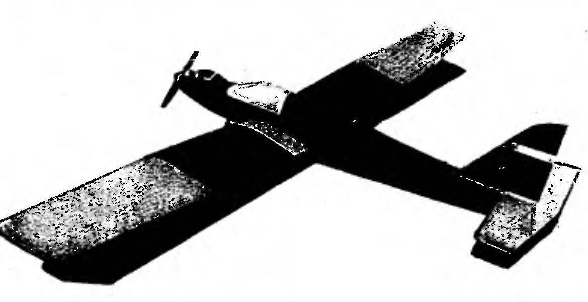
We present radiomodulators development created by Czech athletes. Although the model presented by the authors as “glider”, its capabilities are much greater. Suffice it to say that a powerful engine with a working volume of 3,5 cm3 this machine can even be used as Aeromexico to slip the glider with a wingspan of up to 2.8 m! Very good “Stratos” — is the name of this interesting aircraft — and behaves as a purely motor technology, and as a glider.The basis of the fuselage are two symmetrical side cut from balsa wood with a thickness of 4 mm. In the front they are strengthened by adding plywood with thickness of 1 mm. from inside the Engine compartment on the sides further inlaid balsa thickness of 10 mm, which allows you to securely attach engine mount out of plywood with a thickness of 9 mm. the Tail part of the fuselage assembled using balsa stringers and racks section 3×6 mm.

When you build the fuselage first, put the frames and connecting the nasal part. The frames themselves are made of plywood: the front (under engine) with a thickness of 9 mm, next — plywood with a thickness of 3 mm and two underwing — 6 mm. Under the engine mount is glued to the tin plate, repeating the contour of the plywood detail and designed for soldering the nuts under the motor attachment screws. The entire power part of the fuselage going in epoxy resin. Waiting for the resin curing, check the accuracy of the Assembly and then put the bulkhead and the wall of the compartment to accommodate the fuel tank. Epoxy mounted the tank, which is laterally reinforced by a balsa plates 3 mm thick. the Tail part of the sidewall connects the balsa boss section 15×20 mm. Then put the cross strut of the fuselage from reek with section 3×6 mm, after which the pasted node to the reception of the rear wheels.
 
The fuselage bottom behind the wing is sheathed with balsa 3 mm thick, with transverse layers of wood. Before trimmed from the bottom “sandwich” of three-millimeter balsa and plywood with thickness of 1-1,2 mm (outside). The front end of matousek closes the balsa thickness of 10 mm. is Fitted and then pasted plate-the base of the main landing gear is made of plywood thickness of 3 mm (in the case of fastening the chassis with the screws you need to take a plywood thickness of 6 mm). The upper tail of the fuselage fixed bed of the stabilizer out of plywood with a thickness of 3 mm with taped nylon nuts M4. Right in front of him set the balsa keel plate thickness of 4-5 mm, which is laterally reinforced by the balsa of the same bars, facing in profile to the last prosperous fairing.
Now it is a test installation of motor and servos. After the installation of the stabilizer with the Elevator it is necessary to adjust the length of the rods of both rudders, which are presented in pairs glued by strips of pine with a cross section of 3×5 mm with wire okoncovke. Craving for carb motor — Bicycle spoke or wire rope in a sheath (“Bowden”).
 
After the control elements are extracted and start the installation of the fairing of the fuselage. To the upper cross struts of balsa glued five polosamota thickness of 2 mm, the cut of which is mounted the stringer cross-section 3×6 mm. the Covering of the fairing is balsa strip thickness of 4 mm On the finished fuselage gargrot processed to a thickness of plating of ZMM. The section above the tank is filled with bar thickness 22 mm, profiled in accordance with the drawings. “The canopy” you can stamp out of Plexiglas, or celluloid or made of foam, and then paste over it with paper followed by painting (it is better to apply easily processed and insoluble nitrosative adhesives, for example, stationery casein).
 
Fig. 1 . Geometricheskie the basic parameters of the model
 
Fig. 1 . Geometricheskie the basic parameters of the model.
 
Fig. 2. The fuselage
 
 
Fig. 2. Fuselage:
1 — front boss (balsa thickness of 10 mm), 2 — the elements of the wall matousek (balsa, 10 mm thick), 3 – motor mount (plywood 9 mm thick), 4 — unit plating compartment of the fuel tank (balsa, thickness 22 mm), 5 — motor frame (plywood 9 mm thick), 6 — strengthening side sheathing (plywood with a thickness of 1 mm), 7 — light (plexiglass), 8 — frame chassis (plywood thickness of 3 mm), 9 — front underwing bulkhead (plywood thickness of 6 mm), 10 — loginentry element side (balsa, thickness 4 mm), 11 – frame fairing (balsa, 2 mm thick), 12-upper fairing stringer (balsa, cross 3×6 mm), 13 — trim fairing (balsa, thickness 3 mm), 14 — rear-wing frame (plywood with a thickness of 6 mm), 15-frame Rastorotsky frame tail (balsa, cross 3×6 mm), 16 -stringers (balsa, cross 3×6 mm), 17 — insert (balsa, thickness 3 mm), 18 — fairing (balsa), 19 – keel (balsa thickness. 4…5 mm), 20 – rudder (balsa, thickness 4…5 mm; handle to the wedge section), a 21 — tool insert of the stabilizer (plywood 3 mm thick with threaded fungi), 22 — rear boss (balsa, thickness 15 mm) 23 — wheel 0, 35 mm, 24 — hour (wire OVS 0 2 mm), 25 — Logement plate stand (plywood with a thickness of 3 mm; the curved end of the bar to sew the thread with glue to the plate), 26 — lower valance (balsa thickness 3 mm), 27 — on Board (balsa, 4 mm thick), 28 — tool insert stand front of the chassis (plywood thickness of 3 mm), 29 — stand (made of anodized aluminum, thickness of 2.5…3 mm), 30 — 50 mm wheel 0, 31 — gain (plywood with a thickness of 1 mm), 3 2 — covering (balsa, thickness 2 mm), 33 – cradle tank (balsa, thickness 3 mm) 34 — the bottom of matousek (balsa, thickness 10 mm) 35 — pins under the rubber band wing mounting and landing gear (beech, 0 6 mm).


R and p. 3. Stabilizer with steering wheel
 
R and S. 3. Stabilizer with wheel:
1 — ending (balsa, cross section 5×15 mm), 2 — power leading edge (balsa, 5 mm thick), 3 – spacer (balsa, the cross section of 3×5 mm), 4 – trailing edge (balsa, cross section 5×17 mm), 5 — top plate (plywood with a thickness of 1…2 mm), 6 — Elevator (balsa, 5 mm thick; handle to the wedge section).

 
Fig. 4. Console wing
 
Fig. 4. Console wing:
1 — plate (plywood with a thickness of 2 mm), 2 — rib composite force of the wing (plywood with a thickness of 2 mm), 3 — the leading edge (balsa, cross section 10×13 mm), 4 — double-sided skin of the forehead (balsa, 2 mm thick), 5 — shelf front spar (pine, 3×8 mm in cross section), 6 — wall of the spar (balsa, 2 mm thick; put on the scale), 7 — standard rib (balsa, 2 mm thick), 8 — pad ribs (balsa 2 mm thick), 9 — shelf rear spar (pine section 2×5 mm) 10-ending (balsa), 11-the top element trailing edge (balsa, cross section 2×40 mm), 12 — lower element edge (balsa, cross-section of 2×35 mm).

 
R and p. 5. Pausable frames fairing of the fuselage
 
R and S. 5. Pausable frames fairing of the fuselage.
 
Fig. b. The root end of the airfoil
 
Fig. b. The root end of the airfoil:
1 — leading edge, 2 — front part of the compound rib of a 3 — sided covering of the forehead, 4 — shelf front spar, 5 — the wall box under bagineti pins (plywood with a thickness of 2 mm), 6 — the covering of the wing, 7 – shelf rear spar 8 — insert (pine section 2×5 mm), 9 — wall box (plywood with a thickness of 1.5 mm) 10 —the back part of the ribs 11 is the top element of the rear edge 12, the lower element of the rear edge 13 — typical rib, 14 — the wall of the spar, 15 — pads rib. Bagineti pins are made of hardened sheet of aluminum and have a height of 16 mm (main front) and 11 mm (rear). Form of patterns needs to provide a specified angle “V” of the wing. Full scope of both pins is approximately equal to 250 mm.

 
Wing patterns are formed by two detachable consoles, tumbling through the dural plate pin-baynetov. For the manufacture of the wing, it is first necessary sheet metal to prepare templates of the ribs and to cut out all the pieces of the cross set of balsa wood with a thickness of 2 mm. Only the root ribs are cut out of plywood with a thickness of 2 mm. basal In the details window provides for mounting of the canisters under the pins. The latter should be made of hardened duralumin with a thickness of 4 mm (main front) and 2 mm (rear).
 
In the Assembly of the first consoles to a smooth Board-the slipway prikreplyaet bottom sheet hard skin of the forehead of balsa 2 mm thick. To it is attached the bottom shelf of the spar (pine or spruce a section of 3×8 mm). After marking the place is on the stocks and the bottom shelf support spar (pine section 2×5 mm), followed by the rear edge of the balsa 2×35 mm (more precisely, the lower trim panel edges). Now for the ribs. After you install the top shelves of the side members of the same sections and at the bottom, pasted to the walls out of plywood with a thickness of 2 mm, forming the root portions of the spars “equalizer” under the lugs of the hinge wing. This Assembly is based on epoxy resin with additional rails section 2×5 mm on the rear spar.
 
All consoles span the space between the flanges of the main spars is filled with balsa wall thickness of 2 mm. Still on the stock top mounts the cowl trailing edge (balsa 2×40 mm). The upper part of the rigid skin of the forehead (balsa, 2 mm thick) is glued first to the spar, then the ribs, and in the end to the front edge. The last before the installation of pre-profiled balsa slats section 10×13 mm. Root of the wing also stitched balsa plates with a thickness of 2 mm. In the places through which it will pass the rubber band wing mounting on the fuselage, lining is enhanced by with plates of plywood with a thickness of 2 mm. These pads better embedding in the balsa cladding on the bottom surface. All the ribs are enhanced through the use of shelves from balsa wood with a thickness of 2 mm. the Fins are made of balsa sticks, before attaching to hollow out the inside to facilitate.
The Assembly of the consoles is completed by mounting the root ribs (the window for the pins to perform better in them), and protrusions on the lower surface of the wing, affecting the rubber mounts at the same time will pull together to console each other.
 
The frame of the stabilizer is assembled from balsa strips cross section 3×5, 5×15, 5×1 mm. y 7 the Central zone is strengthened additionally by covering the top with plywood with a thickness of 1-2 mm. the Entire front edge of the power is made of thick balsa plate with a thickness of 5 mm. the Elevator vystragivaetsja from lightweight wood and has a wedge-shaped cross-section.
 
Along the axis of the stabilizer are drilled two holes for the nylon screws M4. The surface of the keel and rudder are made of sheets of balsa with thickness 4 — 5 mm, and the front edge of the keel only kruglitsa, and all over is given a wedge shape. After covering and lakirovanie elements of plumage are mounted on them hinges and the rudders are hung on nylon hinges.
 
‘Front wheel sawed from the hardened duralumin with a thickness of 2.5 to 3 mm. after the Processing of the workpiece contour, in her drill hole 0 5 mm below the axis of the wheels (the optimal size of the last— 0 to 50 mm). Rack can be mounted on the fuselage using rubber bands, moving through stuck in the fuselage styrene 0 6 mm, or by means of polyamide screws. Front tail wheel, bent steel wires of 0 2 mm, the fuselage is based on the insertion of thick plywood
 
3 mm. of the place of incorporation of spilled epoxy. The tail wheel is “polypragmaty” 0 35 mm.
 
The proposed model to determine the engine displacement from 2.5 to 3.5 cm3 (the author recommends the MVVS-3.5, which corresponds approximately to domestic MDS is 3.5). If the model is quite easy and you will use it without the landing gear (of course, not as Aeromexico), the required thrust will provide even the engine volume of 2 cm3 in good condition. When using engine 3,5 cm3 is well established propeller size 220×110 (diameter x pitch). Power system it is useful to equip the spinner of the propeller. The fuel tank is plastic, with a volume of approximately 200 cm3. In the power supply system of the engine, you must enable the filter.
 
When the wrapping and decoration using traditional materials and technologies. Initially, all elements in the model is carefully polished and triple-coated with nitrocellulose lacquer. The wing and stabilizer — micuenta, pulled over by fivefold application of Amalita (stabilizer only three layers). Other parts off with three coats of nitro lacquer. The entire model is painted with nitrocellulose. After drying, all surfaces are protected with two-time application of a clear synthetic varnish.
 
The systematic use of the “Stratos” as Aeromexico you need to consider that the wire length of 30-40 m should consist of two parts. The first (approximately two-thirds of the total length) represents a durable nylon cord. The second is made from nylon fishing line 0 0,3 — 0,4 mm is the damper and fuse. In critical situations this part of the towline breaks, then both models fly on their own.
 
At the start of the model towing scattered on the ground, while the towed glider leaves the hands after attaining sufficient takeoff speed. You must strictly adhere to one rule: the first turn can start only after a set of a considerable height, and the radii of the bends intentionally increase compared to running a single model. After the climb, the pilot of the tug gently removes the gas engine and the pilot of the glider, waiting for the slow-speed flight “aeropoezd” gives Elevator down, driving thus the glider. Recepca automatically.
 
When using the “Stratos” in the main option as of Aeromexico, the first outside prosperous have not balsa, and three-millimeter plywood. The inside of the fuselage to it “sew” or screw lug wire 0 2 mm, which subsequently will be fixed towline. On the model of the glider enough to stick in the forward fuselage sloped pin. It put on when running a steel ring, which Ends coming from the tow rope.

Recommend to read

  • CAN AND CONECAN AND CONE
    The one who often have to use a vise knows that the most difficult thing is to hold them a wedge-shaped or cone detail: when processing it loosened and slips out. However, if you apply a...
  • SIGHT – CHAMPIONSHIPSIGHT – CHAMPIONSHIP
    The magazine "M-K" in the last few years has published a number of interesting patterns with rubber motor, with an unusual decision nodes, and technological methods of their creation....