 In June, 1961, AGARD released requirements NBMR-3, to tactical fighter-bomber and scout, intended to replace in service aircraft G. 91R, F-104G and Mirage III. It was assumed that the first squadron of new aircraft, the relevant NBMR-3, due to enter service with NATO in 1967.
The most important condition requirements NBMR-3 was to enable the utilization of the aircraft from unpaved paths of length more than 200 m. the Maximum speed of the aircraft at the ground is subsonic, corresponding to the number M=0,92, but at high altitude the aircraft was to have supersonic flight speed corresponding to Mach number=1,5. Tactical radius of action was supposed not less than 460 km. Weight combat load for the aircraft was not specified, but provided that it needs to carry tactical nuclear weapons.
After the release of the demands announced the beginning of the contest that various European firms have submitted more than 20 projects of fighter-bombers. However, the final decision about the choice of a supersonic fighter-bomber meets specified requirements to do so and failed. And then Italy and Germany decided to continue work on the aircraft. In may 1963, these two countries signed an agreement on joint development of vertical take-off reconnaissance and combat aircraft called the VAK 191 (Vertikalstarten des Aufklarungs – und Kampfflugzeug). The number “191” indicated that the aircraft first and foremost meant to replace the G. 91. Requirements, the speed of the new plane had to be at least M=0,92 for the height of 150 m, and the radius of the load 907 kg -460 km.
Candidates for mass production became the aircraft:
VAK 191 A – R. 1127 Hawker MK.2;
VAK 191В – Focke-Wulf FW 1262;
VAK 191С – EWR-EWR Sud 420;
VAK 191D – FIAT G. 95/4.
Italian VTOL G. 95 was done at the company FIAT. In the most perfect option – G. 95/4, the vertical thrust was used four lifting turbojet engines Rolls-Royce RB.162-31 with a thrust of 2000 kgf, installed at the tandem scheme in the Central part of the fuselage. This design reduces the risk of loss of control when failure of one engine. The required longitudinal balance is ensured by pumping fuel between the fuselage tanks. In the rear fuselage wanted to install two propulsion turbojet engine General Electric J-85 with afterburner and thrust 1860 kgs each, or single Rolls-Royce RB.153-61 with a thrust of 2700 – 3200 kg.
Calculations have shown that the G. 95/4 could do a vertical takeoff, with a takeoff weight of 7,000 kg. the profile of the typical sorties included flight to the target, the remote distance 340 km, at an altitude of 150 m, and the first 170 km, the aircraft flew at a speed corresponding to the number M=0,6, and further with a speed corresponding to the number M=0,92. After a combat mission the aircraft was returning to base, repeating in reverse order the flight profile to the target.
German VTOL 420 EWR. EWR-Sud (*Approx. authors. – Concern EWR-Sud was established in February 1959 by the merger of the firms of Heinkel Flugzeugbau GmbH, Messerschmitt Bolkow GmbH and AG) was a subsonic version of the fighter-bomber, the VJ 101D, a project that is result of joint creativity of engineers EWR-Sud and experts from American firms Boeing and Republic.
In his scheme, he was reduced to the British TSR.2 on the fuselage, high aspect ratio, small Delta wing and single-fin tail unit. VJ 101D wanted to put five lifting turbojet RB. 162-31 and two lifting and propulsion RB. 153-61, with additional vertical nozzles and devices redirect thrust down. It was supposed to build two experimental VJ 101D. In 1964, the construction of the first instance has been started, but after a few months it stopped. The group began work on a new German-American aircraft with a variable sweep wing AVS (an acronym for Advanced V/STOL – a streamlined aircraft with vertical or short takeoff), which gradually transformed into the European program MRCA – multi-role combat aircraft (Multi Role Combat Aircraft) led to the creation of the fighter-bomber Tornado (see A In “M-K” at No. 2 for 2009).
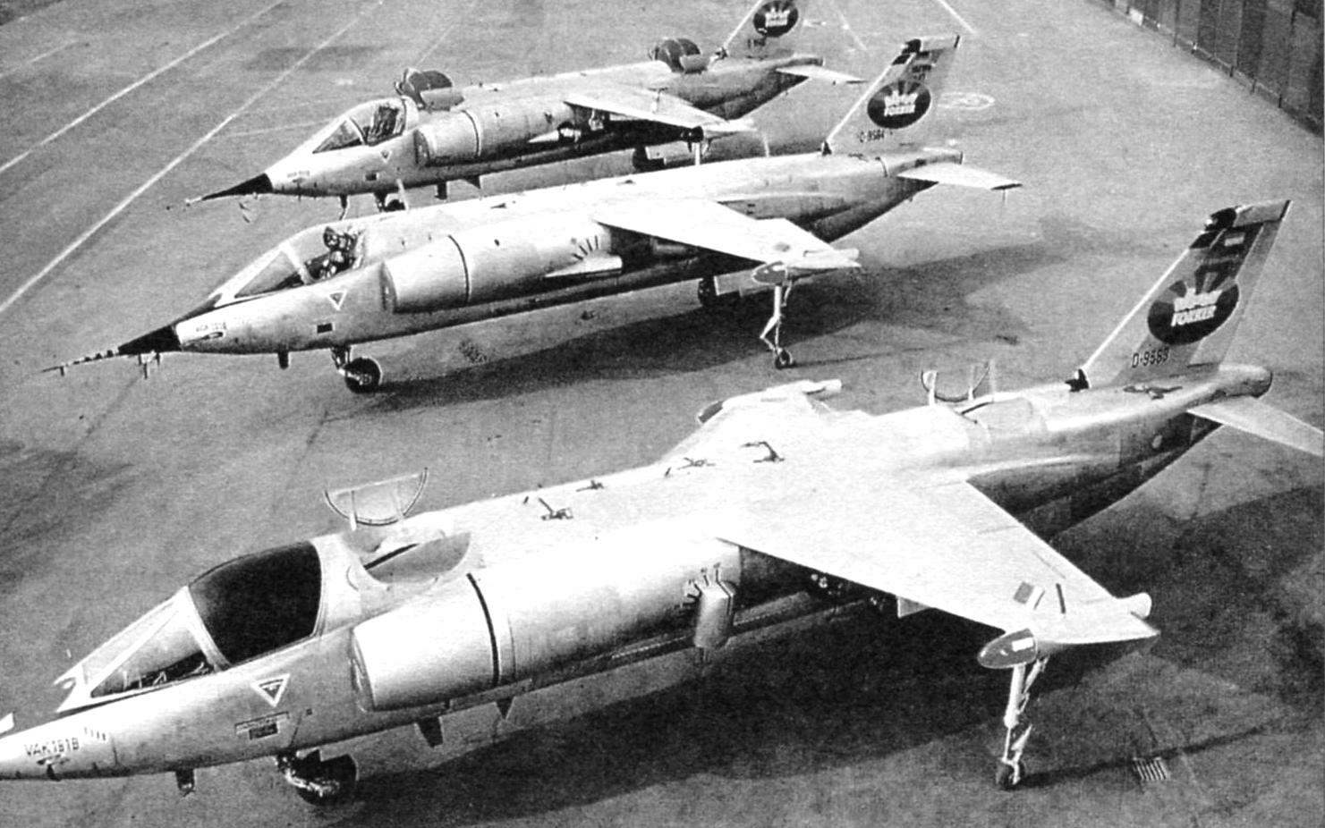
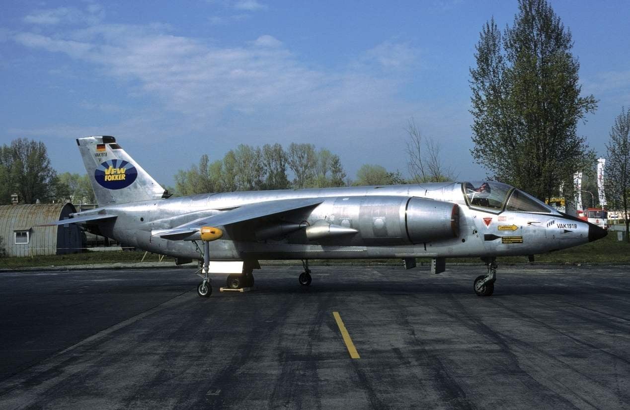
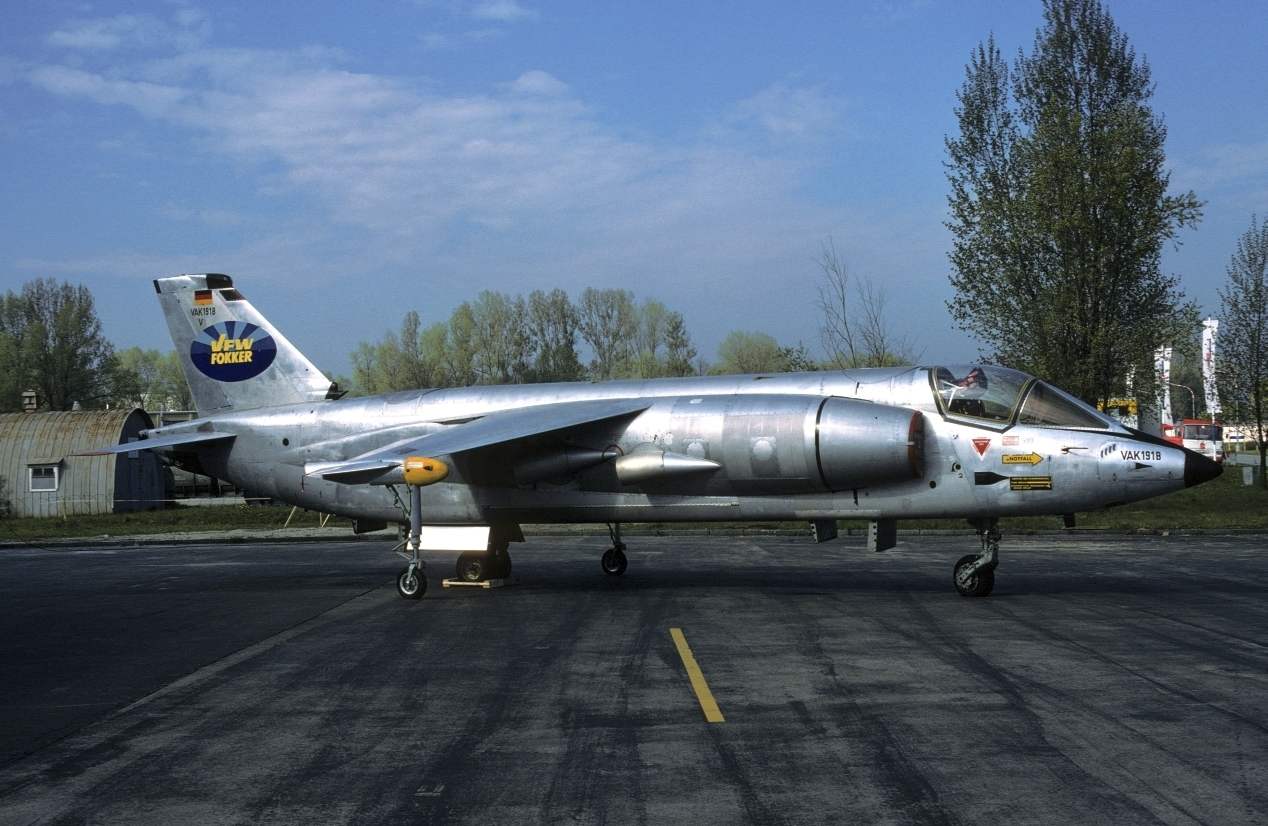
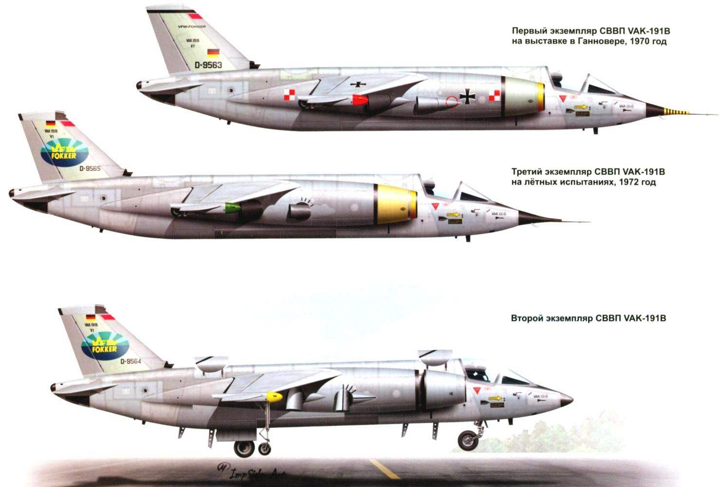
Three prototypes VAK 191В
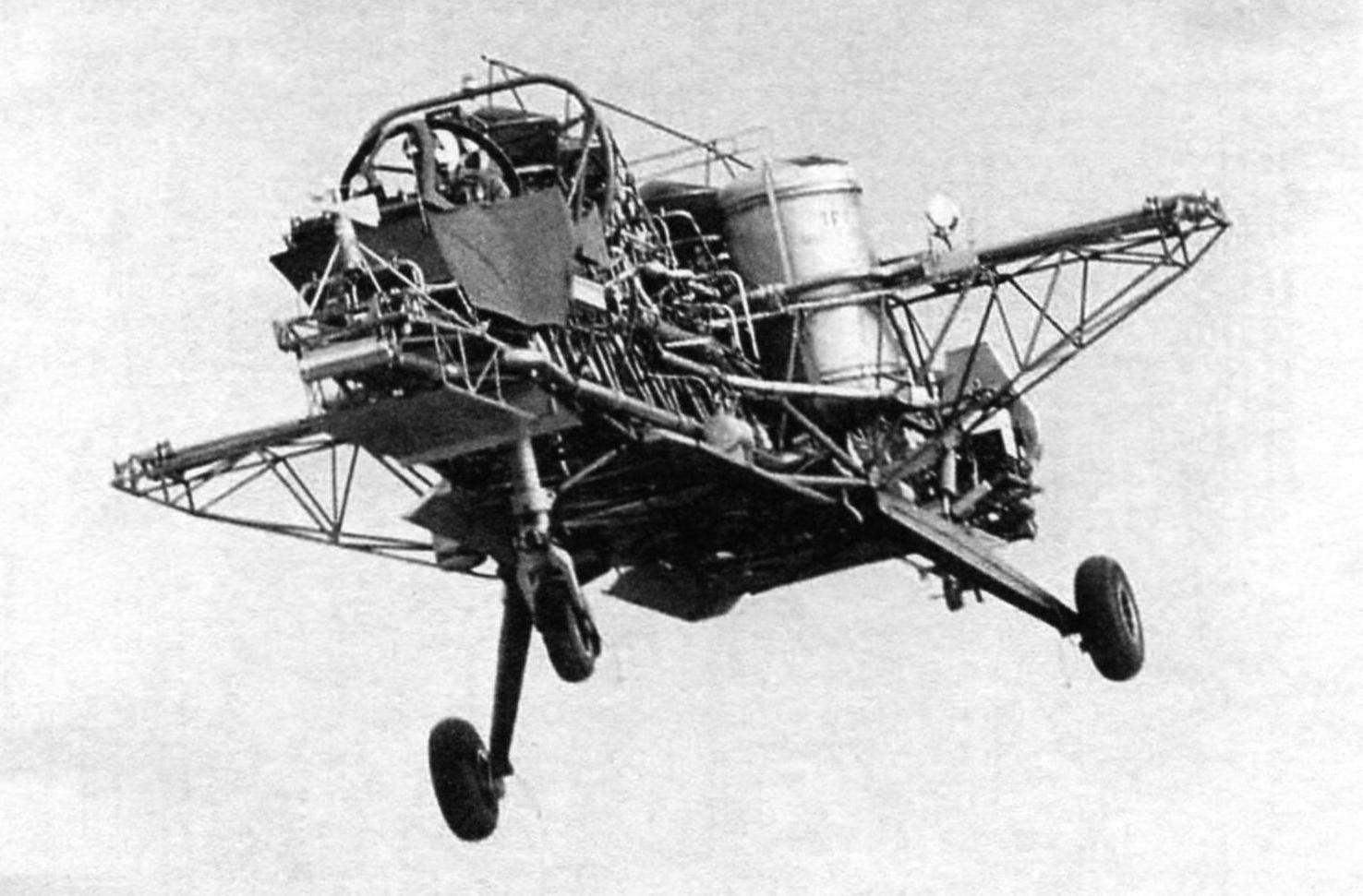
Flying stand SG 1262 in free flight. In the bow-mounted cabin layout VAK 191В
Project FW 1262 in its layout were very close to British R. 1127, but differs from it by the presence of two lift engines of the RB.162 creating half of the required vertical thrust. They were located front and rear of the lifting and propulsion turbofan turbojet (turbofan) BS.94 with four rotating nozzles installed in the middle of the fuselage.
British R. 1127 participated only in the comparative part of the contest and acceptance of his on the arms was not planned.
Analysis of the three projects, conducted in August 1963, showed that the power plant of the FW 1262 provides the best weight and takeoff and landing performance for combat aircraft VAK 191. If we consider the dependence of take-off weight contenders from the fraction of the vertical thrust produced by the lift engines, the weight FW 1262 is 35 – 40% lower than the p. 1127, and almost 10% lower than the EWR 420. Thus, he was close to optimal with respect to the minimum take-off weight. VAK 191В declared the winner. The estimated order for the Luftwaffe amounted to 200 aircraft, and for the Italian air force – 100.
The main developer VAK 191В recently created concern VFW – Vereinigte Flugtechnische Werke GmbH* (*Approx of the authors. – VFW founded in 1964 merger of Focke-Wulf and Weser Flugzeugbau GmbH). FIAT and EWR-Sud became subcontractors. To control the development of the aircraft was created by the German-Italian Committee of Directors of VAK program, the working groups which dealt with purely technical matters. Overall management of the programme was implemented test center of the Luftwaffe.
The development of the power plant led the German MAN Turbo (MTU) in collaboration with the British firm Rolls-Royce.
Almost all onboard systems VAK was designed by the firms of great Britain and the United States. The exceptions were the auxiliary power unit, designed by the firm of Klockner-Humboldt-Deutz, and an automatic control system for aircraft (ACS) is a joint development of the VFW and Bodenseewerke.
Test flights were scheduled to take place on the territory of both countries. In Germany, wanted to practice a vertical takeoff and landing as well as takeoff and landing short takeoff and mileage, and in Italy the FIAT pilots planned to investigate the behavior of VAK 191В normal mode.
For testing of automatic control systems VAK 191В the Committee of Directors of the program decided to build a flying stand. It was a truss of tubes with tricycle landing gear. Powerplant 191st was still under development and engineers VFW could not use it on the stand. But that fact does not bother the developers, because in order to obtain as closely as possible to VAK 191В dynamic characteristics, not necessarily copy it in detail, it is sufficient, appropriate modifications of the control laws in the computer ACS.
On a flying stand set five hoisting engines RB.108 in one row. The first and the last – simulated lifting RB.162, and three Central – PMD RB.193. The unusual aircraft was assigned the designation SG 1262. SG from the German word Schwebegestell – flying frame. Control of the spatial position of the stand was achieved by duplicate gas-jet control system. Compressed air for the operation of its core channel was selected from three Central RB.108, and a back channel fed from TRD extreme. Nozzle roll control to be placed at the ends of the cross beam, simulating the wing, and the nozzle pitch control fixed on the ends of the truss of the fuselage. Maximum takeoff weight was 3,900 kg fuel capacity in two tanks was calculated for 12 minutes of flight, speed at altitude 200 m – 93 km/h.
SG 1262 built on the former factory of the company Focke-Wulf in Bremen, where he began his test. First SG 1262 were tested on the so-called pedestal.
Fighter-bomber vertical takeoff and landing VAK-191:
1 – inlet; 2 – fold intake of the 2nd lifting motor; 3 – fold intake of the 1st lift of the engine; 4 – hinged part of the canopy; 5 – canopy canopy; 6 – extension rod; 7 – operational sunroof; 8 – way adjustable air inlet; 9 – swivel nozzles in the main (horizontal) position; 10 – wing fairing supports; 11 – wing support in the retracted position; 12 – operating panel; 13 – air intake in the maximally extended (open) position; 14 – leaf front lifting motor in the open position; 15 is an anterior (first) hoist motor; 16 – rear (second) hoist motor; 17 – fold rear (second) lifting motor; 18 – say no to the toe; 19 – ANO; 20 – Aileron; 21 – flap; 22 – handlebar height; 23 – tail fairing; 24 removable operating panel; 25 – removable bottom service panel; 26 – fold output device rear (second) lifting motor; 27 – fold niche rear landing gear; 28 – operating panel; 29 – fold output device front (first) lifting motor; 30 – fold niche of the front landing gear; 31 – hinged part of the canopy in the open position; 32 – ejection seat; 33 – turning the nozzle in the down (starting) position; 34 – fold rear (second) lifting motor in the open position; 35 – gear, rear landing gear; 36 – supporting bearing; 37 – lower fuselage operating panel in the open position; 38 – fold the front (first) of the lifting motor in the open position; 39 – wheel front support; 40 – the front landing gear
A full-scale mockup of the aircraft VAK 191В
Testing of the first prototype VAK 191В on the podium
The pedestal is a cylindrical vertically mounted pylon, the height of which could change the hydraulic Jack. At the end of the pylon was fixed to the subject aircraft. The mounting mechanism allowed the camera to have some freedom of movement on all three axes. Around the pedestal was concreted wells for discharging a jet covered with metal bars. Unlike traditionally used for testing a VTOL aircraft cable suspension, pedestal gave greater security and provided a very high accuracy of measurements during the experiments. In addition, engineers could easily restrict the freedom of movement of the apparatus and to check its behavior only in one channel, e.g. roll, pitch and heading hard to fix.
The first flight simulation SG 1262 on the podium with all the free axes took place on 21 January 1966. Only the unit made 183 flight simulation for a total duration of 262 hours.
August 5, 1966, chief test pilot of the group VFW Obermaier Ludwig (Ludwig Obermeier) made on the stand first free flight. SG 1262 behaved steadily, the control system worked well in both automatic and manual control mode. In subsequent flights, special attention was paid to the analysis of handling characteristics during hovering. Studied various methods and the trajectory of the landing and transition to horizontal flight after takeoff. Numerous test data recorded by the flight recorders to tape.
In flight also tested the bow model VAK 191В, to verify visibility from the cockpit during vertical takeoff. Before the pilot put the front part of the canopy VAK 191В, but without glasses, and truss around the chair pilot sheathed with canvas.
In flights SG 1262 participated actively test pilots FIAT Pietro Treviso (Pietro Trevisan) and Manlio, Quarantelli (Manlio Quarantelli). The General public met SG 1262 in August 1968 at an air show in Hanover. In total, the flight test program lasted more than two years. The stand was test flown by 12 pilots. Your last 141 flight SG 1262 made on 13 November 1969.
While there was test flights of the stand, the designers under the direction of Dr. Ralph Richiusa (Ralph Riccius) worked hard on the project plane.
Based on the fact that their combat missions VAK 191В had to perform at low altitudes, which are characterized by high turbulence, the maximum attention of engineers focused on reducing congestion when flying in turbulent air. For this purpose the aircraft wing was chosen with a high specific load, a low elongation and a relatively large sweep angle is about 40° at the 1/4 chord. Wing loading even higher than the wing loading of the F-104G. The “Starfighter” in the normal takeoff weight of 9000 kg, it amounted to 494 kg/m2, and VAK 191В at take-off weight by one ton less – 639 kg/m2. But such “record” numbers are not very bothered designers, because VAK were lifting engines and takeoff and landing performance, the default was superior to the performance of the F-104G. Well, the lack of wing lift in horizontal flight offset a small tightening angle PMD nozzle, front nozzle decided to install an angle of 6° 30′, and the rear is -5°12′.
Due to the installation of PMD in the Central part of the fuselage for VAK 191В chosen scheme vysokoplan. Improving the stability, the wing was given a negative angle transverse V – 12°30′. To reduce the landing speed when landing with the mileage and reduce the length of the transitional phase during vertical takeoff, the wing was equipped with flaps and drooping ailerons.
The tail Assembly consisted of all-moving stabilizer with a magnitude of 3.41 m and keel with rudder. As a wing, stabilizer stood with a negative angle transverse V – 8°.
Front lift engine located behind the cockpit, followed by the front fuel tank and the air intake duct to the PMD. Under the tank was sealed compartment for reconnaissance equipment.
Free volume under MIP occupied a small cargo Bay, which could accommodate a nuclear bomb, or additional reconnaissance equipment, or fuel tank.
Conventional weapons wanted to hang on four pylons under the wing.
In the rear fuselage mounted fuel tanks, which housed the rear lift the engine and compartment with auxiliary power unit. It provided VAKy independence from special ground-based facilities and has opened up the possibility for a concealed landing on unprepared sites.
To fly from such sites, including grass, VAK equipped Bicycle gear with low pressure tires. Small supporting strut retracted into fairings on the wing. When taxiing the front wheel was driven from the pedals. To reduce the distance run in the rear stood a container of a brake parachute, a pilot could use it as anti-spin.
Almost all onboard electronic system was equipped with a built-in self-control. Through these means the opportunity to easily identify the faulty unit without the use of cumbersome controlnativewindow equipment and external power sources that it is easier for the preparation of aircraft for flight in isolation from the base.
The model aircraft has passed the most rigorous, one might even say unprecedented, blowing in wind tunnels of the group VFW and FIAT, as well as in the tube the Aerodynamic laboratory (Aerodynamische Versuchsanstalt – AVA) in göttingen, the German research laboratory for aviation (Deutsche Versuchsanstalt für Luftfahrt – DVL) in Cologne, the British research Association ARA (Aircraft Research Association) in Bedford, in the Dutch national laboratory NLR in Amsterdam and the Swiss Federal aircraft centre of Emmen. Flick characteristics were filmed in France, in a vertical tube in Lille.
On blowing at subsonic speeds spent 4400 hours on the test aircraft performance in transient – 2000 hours, transonic area – 500 hours and 2000 hours left for scientists to study the takeoff and landing.
After purging began development of working drawings. VFW and FIAT built the models of the plane for working off of technology of the Assembly process, the optimal placement of equipment and systems. Began design of production and Assembly equipment. For precise contour of the aircraft in the manufacture of the cladding panels, the engineers built a special layout from a sheet material with a seamless plastic-coated.
When designing the plane tended to divide into separate components which could be manufactured at different factories and in different countries. The distribution occurred as follows.
In Germany was made: the Central section of the fuselage, wing air inlets of the lifting engines, fold deflection of the thrust vector of the hoisting engines, the sash compartment of the front pillar chassis, the top panel of the fuselage, the compartment reconnaissance equipment, cargo Bay doors, air intake, side of the fuselage in the area of the nozzle of PMD, the sash compartment of the main landing gear.
In Italy: the nasal radiotransparent Radome, cockpit, canopy pilot, the aft fuselage, stabilizer, keel, rudder, wing box, the sock of the wing, ailerons and flaps, fairings for supporting the wing landing gear.
To study the characteristics of handling, the reaction of the pilot in case of failure of the power plant and training of future pilots VFW has built a special machine. It was a fully equipped cabin that is attached to the flight simulation complex of two EVM – analog and digital. Capabilities of the simulator allow you to connect actuators of the ACS. Thanks to the engineers managed to eliminate all the possible malfunctions in the aircraft control system before the start of its ground and flight tests.
As hoisting engines on the aircraft used two turbojet Rolls-Royce/MTU RB.162-81. They are distinguished by exceptional simplicity, low weight, maximum reliability and low cost.
The engine consisted of 750 parts. Another positive attribute was the simplicity of its services: besides the daily oil level check and preflight inspection of the air intake, to identify foreign bodies and damage no other operations are not required.
Engine start was carried out on the ground by compressed air from PMD, and the air – flow.
In the design of the engine RB. 162-81 widely used composite materials in particular were manufacturing compressor blades, guide vanes and the compressor casing. Because of this turbojet engine had a very low specific weight of only 0.07 g/cm3.
The engines were connected by a common control system, and their desire was regulated by a separate lever. To preserve the balancing when one of the engines of the second automatic.
RВ. 162-81 were fixed in the fuselage at an angle of 12.5°, which in case of failure of PMD possible to maintain the speed of horizontal flight of the aircraft at the minimum evolutive and gave the pilot the ability to land safely on an aircraft.
Hang or movement VAK 191В ago were produced by deflection of the thrust vector in the desired direction. To do this, at the bottom of the fuselage in front of the nozzle of each lift TRD stood for two controlled doors with heat-resistant coating. In horizontal flight, these flaps work as air brakes.
Entrainment in the lifting engines of hot gases and any items from the ground almost excluded. Their air intakes were on top of the fuselage, and the jet reflected from the runway, reaching them, have already lost most of his energy.
As for the impact of RB.162 on the service life of a concrete runway, then Rolls-Royce has conducted the relevant tests and said that the standard of the airfield plate was kept approximately 50 vertical take-offs from the same place, while there was a slight or partial erosion of its surface. If the concrete before takeoff poured down water, the erosion was fully absent.
Turbofan Rolls-Royce/MTU RB.193-12 by design, reminiscent of the Pegasus engine of the Harrier aircraft, but were smaller in diameter. He had a four-speed fan driven by a single-stage low-pressure turbine. A large part of the air injected by the fan is thrown out through the front, the so called “cold” rotary nozzle of the engine. The rest of the air passed through a three-stage low pressure compressor, eight-stage high pressure compressor, annular combustor and impinge on a three-stage turbine. The exhaust gases ejected through the rear hot nozzles. To compensate for the torque, which could degrade the controllability in hover mode, the fan and the compressors are rotated in different directions for nested into each other shafts.

The first flight of the first sample VAK 191В
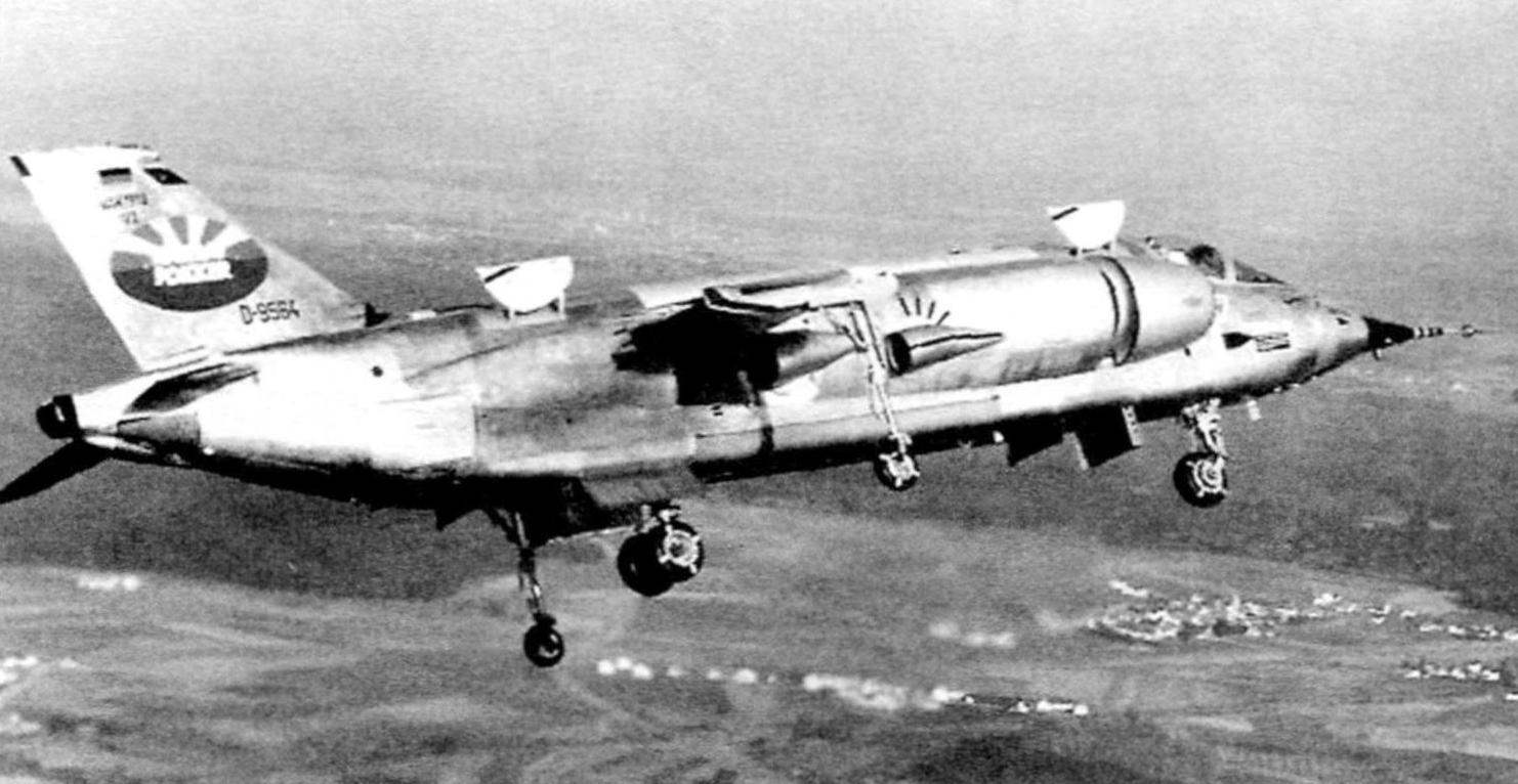
The second prototype VAK 191В in the first flight. The keel is a logo of the United Corporation VFW-Fokker
All four nozzles are rotated synchronously. For vertical take-off nozzle turned 90°, and for the deceleration and transition from horizontal flight to vertical 100°.
The motor starts from the auxiliary power unit of the type T. 112 located in the rear of the aircraft.
Air for work, the PDP came through the unregulated side of the air intakes. On the background of a bulky intakes of the Harrier aircraft, which because of its size and the characteristic bulging of the species was nicknamed “ears”, the air intakes on VAK 191В seemed quite small. Of course, their performance on the ground and in hover mode was clearly insufficient for the stable operation of the engine. Therefore, to increase air flow, the engineers used a special mechanism, it for the two guides moved the forward part of the air intake opening for secondary air in a wide gap. The total air flow through the intake has increased by 70%, which completely covers the needs of the RB. 193-12. Is unique in the history of aviation the solution allowed to refuse a cut in the skin and traditional spring-loaded valves, which increased the resistance of the air in normal flight and reduced aerodynamic quality of the aircraft.
Bench tests of the first engine began in December 1967.
For studies of unusual intake and effects at the ingress of exhaust gases and also to measure the intensity of noise and temperature on the surface of the plane and around it firm MTU made a special stand. It was a layout of the Central part of the fuselage with lifting and sustainer engine. Test stand took place until the beginning of 1970, after which all engines were transferred to the plant in Bremen VFW for installation on experimental aircraft.
Total was ordered and built six copies of RB. 193-12.
The engines of the aircraft provided by the system jet control. At the same time from their compressors were selected about 10% of the compressed air. To improve the reliability of all jet rudders is duplicated. Inkjet office has begun work in the case of the twist nozzle of PMD at an angle greater than 20°.
Nozzle rudders were associated with aerodynamic controls, rejected by the pilot by means of handles and pedals. VAKe mounted on front fly-by-wire control system (fbwcs) with triple redundancy, which has passed successful tests on a flying stand SG 1262. A very important advantage of this system over the traditional was its reliability and performance, lower weight and ease of operation. In case of failure of all three channels, the EMF was an automatic switch to the backup hydraulic control system with high working pressure – 280 kg/cm2. Due to such unusual for that time the pressure was able to reduce dimensions and weight of the actuators to EMF and increase the speed of their work.
At flight speeds of more than 333 km/h in the EDS worked like a normal automatic control system, campfire oscillations of the aircraft. By reducing the speed below this threshold, the wings no longer held the aircraft, the nozzle of PMD turned around and in the works include the jet rudders. The EDS passed in a vertical mode of flight in which any deviation of the control knob corresponded to a change in the angular position of the aircraft and not change its angular speed, in other words, management started to work in a helicopter. The maximum value for the angles of pitch and roll in hover mode was limited to the value of 15°.
To guarantee the rescue of the pilot, in the event of an emergency situation in the cockpit VАК 191В installed ejection seat Martin-Baker Mk.9 the class of “0-0”.
Sighting and navigation system on Board the aircraft was not established.
In the beginning, the project VAK 191В had a very big importance for West Germany. Oddly enough, but the aviation industry revived after the war, he worked mainly on military needs. The share of civil orders does not exceed 10%. Until the mid 1960-ies of the production facilities were loaded serial production aircraft, the G. 91 and F-104G, but then prosperity could have ended a new major orders was not expected. In this regard, the Germans developed an ambitious plan for upgrading all of its aircraft to aircraft with vertical takeoff and landing. To start this process like in the late 1960-ies. Updated the combat strength of the Luftwaffe was as follows: fighter-interceptor on the basis of the VJ 101 C, a fighter-bomber based on VAK 191В and military transport aircraft Do 31.
However, the German scientists, engineers and military overestimated its strength. For the full development of such complex projects have required much more time and money. Moreover, in 1966 in the course of events interfered with the economic crisis. The Department of defense has reduced its military spending by 15%. The Committee of Directors of VAK had to reduce the cost of the program and to renounce the double version of the aircraft, reducing the number of samples is under construction to four.
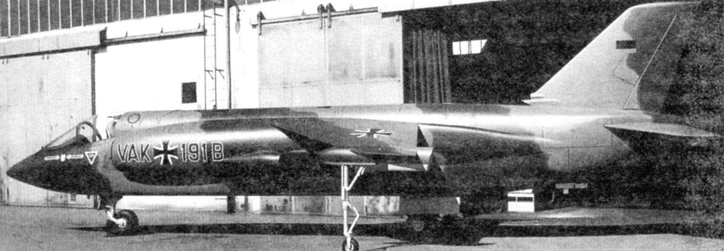
Reduction program has been greatly affected by the timing of the start of flight tests. The construction of the aircraft behind schedule by as much as two years. Rolled out the first prototype from the factory shop in Bremen took place only on 24 April 1970, although earlier it was planned for 1968.
Aircraft # 1 was assigned a civil registration number D-9563. Started ground tests. First I tested the power plant, then the engineers have begun testing a control system using a pedestal. VAK 191В were fixed on him in the area of its centre of gravity and with the included engines worked through the set programs. This stage was the longest and took almost 18 months.
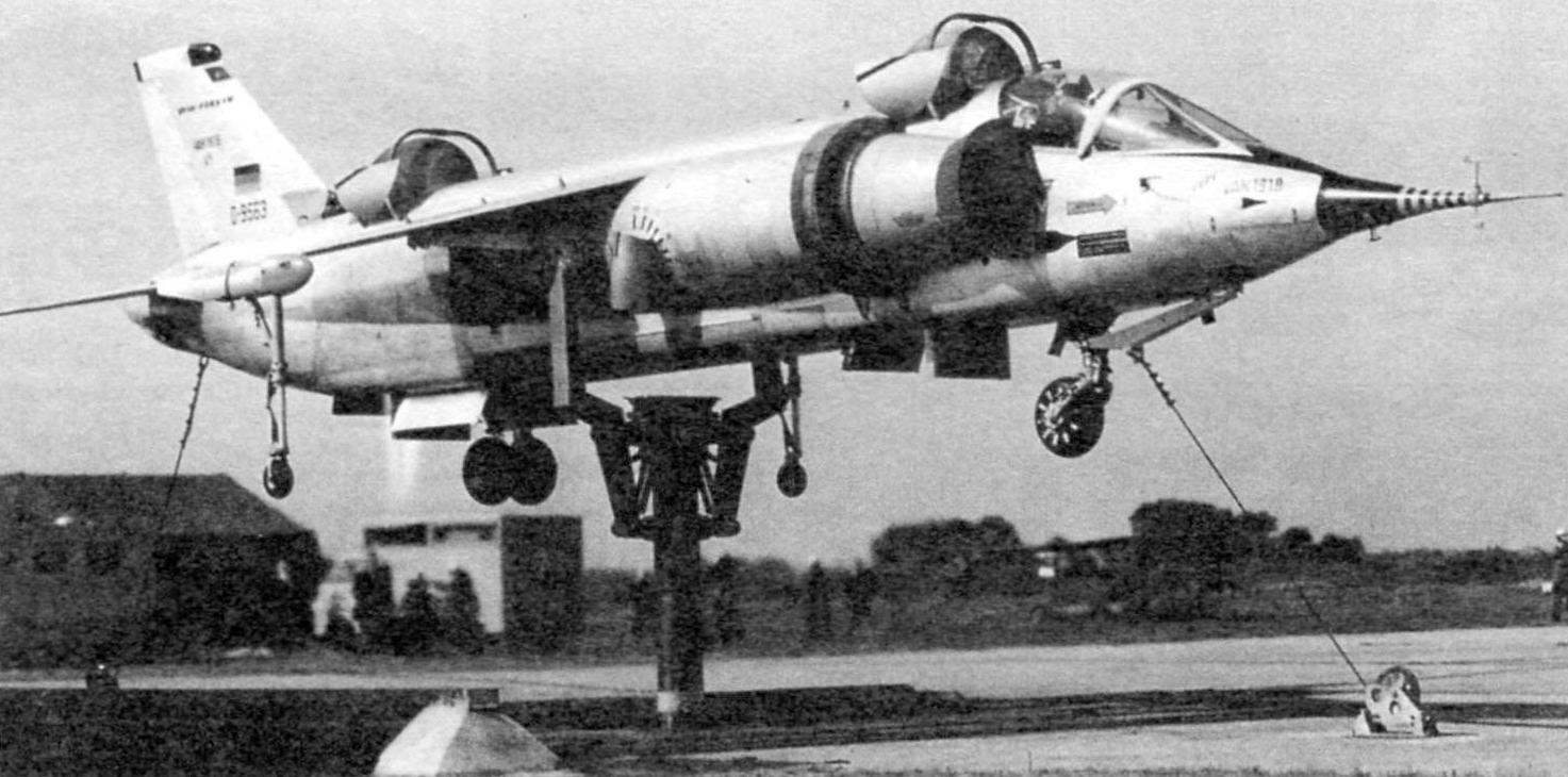
The first flight of the No. 1 scheme “a vertical takeoff – vertical landing” took place on 10 September 1971. Duration – 3 minutes, 18 seconds. In the cockpit was test pilot Obermeier. First flight in “vertical take-off transition to level flight – vertical landing” took place on 26 October 1972. In horizontal flight Obermeier he sped up the car to a speed of 445 km/h.
Training flights took place with German thoroughness, VAK behaved steadily and all stages of flight tests passed without failures and flight accidents.
The second instance (D-9564) in April 1970, were demonstrated at air show in Hanover. His keel was a logo of the new combined Corporation VFW-Fokker, which was established for the production of regional jet VWF-614. Thus, VAK demonstrated not only the achievements of German aviation science, but also became the locomotive of the advertising company. Its first flight took place on 2 October 1971. Having made a vertical takeoff, the plane flew for almost 3 minutes at a speed of 60 km/h at an altitude of about 40 metres and made a vertical landing.
The third copy VAK 191В (D-9565) joined the test programme in early 1972. Its first flight took place on 17 February.
The airfield in Bremen does not allow full test transients and to check the flight characteristics of the aircraft at different altitudes. So the flights VAK 191В No. 2 was moved to the airbase of the Luftwaffe in Manange, which already has tested other German VTOL VJ-101C and Do-31. In order to disassemble the aircraft for ground transportation, he decided to transfer to the destination by air. 6 APR 1972 VAK secured to the external load transport helicopter CH-53B and, with three intermediate stops is delivered to the destination, breaking the 563 km.
November 30, 1972 it was announced the official closure of the program, and is scheduled for 1973 tests on the program MRCA did not take place.
Only the development of aircraft VAK 191В firms VFW and FIAT has spent over 3 million man-hours of engineering and technical personnel. About 2 million man-hours it took to prepare the production and the construction of four prototypes.
After the program is closed VFW-Fokker has made attempts to rescue the project by offering two new military modification VAK 191В MK.2 and MK.Z.
Subsonic MK.2 could be a direct competitor to aircraft Harrier GR.1. According to the company, the aircraft VAK-191B MK.2 combat load and the radius of action two to three times higher than those of the “Harrier”.
MK.2 differed from the original draft as follows:
– a 50% increase in wing area to improve maneuverability, takeoff and landing characteristics and the payload;
– an increase of 30% podyemnaya engine thrust 5% thrust lift engines;
– installing the sighting and navigation system.
The wingspan is 7.5 m, a wing area of 19 m2, height – 4.3 m, length is 15.3 m.
Supersonic VAK 191В MK.S, with increased fuel capacity and more powerful power plant, proposed for the competition of the US Navy on the development of fighter-attack aircraft.
The plane-the winner was supposed to enter service with light aircraft carriers of the control of the seas – SCS (Sea Control Ship), with a displacement of about 15,000 tons, which is about four times less than standard displacement shock of carriers of the Forrestal. It was believed that a large number of ships SCS will replace the big carriers. It was something like a strategy of dispersal airfields. Only now the planes were rassredotochit on small ships.
Rivals VAKa were four American project and the ubiquitous British “Harrier”. In 1975 VAK 191В flew the American pilots who gave him positive feedback. But the customer preferred to pick a winner among friends. Summing up the results of the competition, representatives of the U.S. Navy announced the two contenders for victory, they were VTOL Convair 200 and the Rockwell XVF-12A.
For VAK 191В it was the final sentence.
Despite the fact that the project VAK 191В was never completed, he left quite a significant mark in aviation history. It applied advanced technological solutions, such as: wire control system, hydraulic system with high working pressure, auxiliary power unit, developed the self-control of on – Board systems are the formal characteristics of combat aircraft, the so-called “4th generation”. Thus, despite his forced experimentalism, VAK 191В can confidently be attributed to this distinguished family, and to say that he was the first fighter-bomber of the “4th generation” in Bundesluftwaffe.
For the time of flight tests of three aircraft VAK 191В made a 91 flight for a total duration of about 15 hours. The last flight took place on 4 September 1975.
FLIGHT CHARACTERISTICS OF THE AIRCRAFT VAK 191B
Wingspan……………………………….6,18 m
The length of the plane………………………….16,28 m
The length of the plane without LDPE…………….14,72 m
Height…………………………………………4,29 m
Wing area………………………….12,52 m2
The empty weight of the aircraft………………….5305 kg
Payload weight……………….2690 kg
The volume of domestic
fuel tanks………………………….2590 l
Takeoff weight……………………………..7995 kg
Specific load on the wing……..639 kg/m2
Specific load
for traction…………………………..0,8 kgf/kgf-thrust
(hover)
Specific load
for traction…………………………..1,7 kgf/kgf-thrust
(cruising flight)
Maximum speed………………M=0,96
at an altitude of 300 m
Cruising speed…………………M=0,92
at the altitude of 12 000 m
Radius………………………….370 km
N. Food reserve was, A. CHECHIN
Recommend to read
 IF YOU NEED MICROBALANCE
If you have to refill the pen or marker ink, there is a need in any microfinance, as the diameter of the housing is quite small. Rescue cover with the "nose" of the plastic bottle with... IN THE SAND WITH OIL
Usually in rural houses and garden plots economic tool stored in sheds or workshops outside of the house. Such areas are characterized by high humidity, corrosion of metal parts. To...
