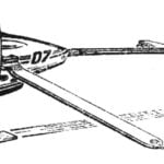
During 1970, our magazine published a series of articles by a group of autogyro designers about the features of building these rotary-wing aircraft, about how to build autogyro models, how to fly gyrogliders towed by a boat or car. At the request of numerous readers, we tell in this issue about the autogyro control system (or gyroglider, since they are identical).
An autogyro in flight, like an airplane, has the ability to move and be controlled relative to three spatial axes: vertical, longitudinal, and lateral. Deflection of the control stick on an autogyro causes the tilt of the rotor plane of rotation, which creates the required pitch or roll moment. Directional control of the autogyro, as in an airplane, is carried out by a rudder mounted on the fin in the tail section of the fuselage.
The movement of the stick and pedals on an autogyro corresponds to the established practice of airplane flight, which is based on the principle of human instinctive movements to maintain balance.
The main general requirements for the autogyro control mechanism are set out point by point — for the convenience of pre-flight checks. Here they are:
- Sufficient control stiffness.
- Minimal control lag due to friction, play, and deformation. It should not exceed the value determined by human reaction speed (1/7 sec.).
- Moderate forces on the stick and pedals. When deflecting them from the neutral position, it is desirable that the forces on them increase smoothly and be directed in the direction opposite to the deflection (the so-called positive stick force gradient).
- Absence of vibrations. There should be no “wandering” of the stick and “jerking” of the pedals.
- Durability and strength. Rotating parts — bearings, ball joints, and pins — must have the required service life.
- Independence of longitudinal, lateral, and directional control. For example, deflection of the stick in the longitudinal direction should not cause roll.
- Absence of jamming in the control linkage and mechanisms during deformation of the fuselage and other parts of the autogyro through which the control linkage passes.
- Presence of limiters for longitudinal deflections of the stick and pedals, which must be installed directly on them.
- Reserve of deflection angles of control mechanisms (slightly more than required by calculation or experimental data).
- Presence of lubrication and protection of joints and rubbing parts from dust and moisture in control connections.
- Convenience of inspection, installation, and disassembly of control units.
The autogyro control mechanism (Fig. 1) consists of control stick 2, lower support 10, lower fork 8, two rods 4, upper fork 7, and upper support 12.
The stick is mounted on the longitudinal beam-fuselage 1 using a bolt, relative to which it can perform oscillatory movements in the longitudinal plane.
Movements of the stick in the lateral plane are transmitted to the fork through a shaft installed on bronze bushings in the lower support housing. On the shaft, the stick and lower fork are fastened with M6 bolts, on the fork side (if necessary) adjusting washers are installed on the shaft to eliminate axial play. From the lower fork, the force is transmitted to the upper one using two rods, at the ends of which there are eye bolts with ball bearings. The upper fork is fixed on the rotor axis, which, in turn, is pivotally mounted on the upper support shaft.
Thus, movement of the control stick in any direction will cause the rotor axis to deflect in the same direction.
The most critical parts in the control mechanism are the forks (Fig. 2 and 3) and their tips (Fig. 4). Therefore, when manufacturing parts, special attention must be paid to the quality of their processing. Welding seams must be even, without cavities and slag inclusions.
Fork blades after bending should not have cracks, folds, or burns. To detect cracks and lack of fusion, it is best, if possible, to X-ray the parts or at least after heat treatment and sandblasting, conduct magnetic inspection.
It is advisable to weld the forks in specially made jigs using arc welding. This guarantees the conformity of the part geometry to the drawing and will eliminate the complex and responsible operation — straightening. Immediately after welding, the forks must be subjected to heat treatment according to the drawings. After heat and sandblasting treatment, the central cups are processed with reamers to the internal size up to Ø 24А3 and the fork ends to Ø 18А3 for mounting the tips.
Fork tips are turned according to the drawing (Fig. 4), but on Ø 10П2а and 18, an allowance of 1.5—2 mm is left. In this form, they are subjected to heat treatment, and then the mounting surfaces are turned to the required size. In this case, special attention must be paid to the quality of processing of the radii of junctions and thread relief groove specified in the drawing.
During assembly, by fitting the mating parts and installing (where required) adjusting washers, it is necessary to achieve clear operation of the entire control mechanism without jamming and play. All nuts must be secured with cotter pins, lock washers, or staked according to the drawing (see Fig. 1).
Directional control of the autogyro, as mentioned above, is carried out by the rudder. The directional control mechanism does not present any design or technological difficulties, and its device and operation are easy to understand from the general view drawing of the autogyro. The dimensions of the fin and rudder can be taken from the same drawing, enlarging them according to the scale. The tail empennage of the autogyro is easy to make by cutting parts from a 10 mm thick plywood sheet. In this case, bracing wires made of ОВС wire Ø 1.2—1.5 mm will have to be installed on the fin. The other ends of the bracing wires are fastened to the transverse beam at the junction points of the struts through M3 turnbuckles.
The disadvantage of the plywood empennage construction is a somewhat greater weight than that of the empennage made from a set of ribs with 1 mm plywood skin. The advantage is simplicity.
To ensure controllability of the autogyro relative to its longitudinal axis, the rudder deflection should be 25° to the right and left from the neutral position. To ensure controllability in pitch and roll, the deflection of the autogyro rotor axis should be 12° in any direction from the neutral position.
Yu. RYSYUK
Recommend to read
 WITH “AIR CUSHION”
Is there any reason to go into specifics slip "school" model, results of which did not even contain the cells in the table of records! If you think about the future, that is. Today we... THE LEG MODULE ON THE ENTIRE SET
In the manufacture of handmade furniture is particularly advantageous to find a solution component structures, which visually unifies the disparate objects in a single set. It is often...
