
 Bomber Handley Page VICTOR. In January 1947 at a meeting Jen 163— secret of the governmental Committee the UK the decision was made to separate the development of the atomic bomb. It followed the refusal of the Americans to pass the English government materials in design and production of nuclear weapons. The plans of the Committee for the development of the first combat of the sample bomb was given five years, and by 1957 it was supposed to produce about 200 atomic bombs.
At the same time began work on designing the aircraft carrier of nuclear weapons. Performance requirements for the new bomber, bearing the code “Document 230”, received on 9 January 1947 in three leading aviation companies of great Britain — A. V. Roe, Handley Page and Vicktrs.
In the specification “B35/46” in this document it was stated that the air force requires high-speed and high-altitude aircraft with a range of not less than 6500 km, and a minimum bomb load of 4500 kg At the end of October 1947 the Ministry of supply held a hearing on the proposed firms projects. The competition was won by the firm of A. V. Roe and Handley Page.
The government wanted to obtain the flying prototypes of the bombers in 1952, the completion of the creation of the first combat of the sample atomic bomb. In February 1949, it became clear that the radical novelty of the proposed projects does not allow to conclude as planned the process of bringing the ordered aircraft. In the interim, it was decided to implement a fairly conservative firm Vickers “660”, called VALIANT
Thus, first took arms, the aircraft that lost the competition, but the company-the winner gets the correct time. One of them, the firm Handley Page, began design of a bomber with jet engines before the official order from the government, almost immediately after the war. In 1946, the leading engineer of the company, Godfrey Lee developed a draft design of the aircraft with four jet engines “Avon” in the root of the wing of the great sweep bent up a law-tsukami. The fuselage was almost the same as the American b-29 bomber. Arrow-shaped stabilizer mounted on the fin a rounded shape.
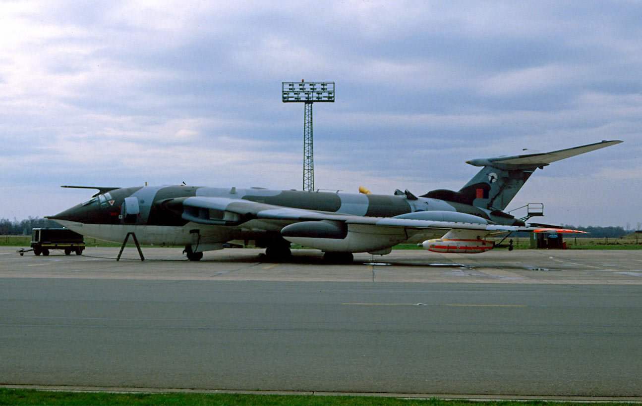
Tanker VICTOR K. 2 of No. 55 squadron Royal air force. The coloring of the war in the Persian Gulf
Great influence on further development of the project had captured German materials on the aerodynamics of a swept wing. In particular, the designers have abandoned the wingtips, which played the role of additional keels. The plane received the designation of signature NR.80, had to have a flight range of 8000 km with a bomb load of 4500 kg at a cruising speed of 830 km/h at an altitude of 15 000 m.
By January 1948, the project completely redesigned, but the name of the old left — new HP.80 became a mid with a Crescent wing and cylindrical, pointed front and rear fuselage and the horizontal tail mounted in the middle of the keel. Under contract with the government as the power plant was planned to use four turbojet F9 (prototype SAPPHIRE turbojet) with the thrust of 3400 kg.
In 1948 the firm was ordered two prototypes of aircraft engines SAPPHIRE. After the wind tunnel revealed that the mid-stabilizer is obscured by streams of air from the root of the wing, and had to be put on the top of the keel. Slightly changed and a Crescent-shaped wing in order to make a constant critical Mach number throughout its scope.
The main objective of the aerodynamicists in designing the machine was the creation of such an aircraft configuration, in which all structural elements, including fuselage and tail, would have the same critical number M is the same as the wing. While it would be possible to get rid of the appearance of local shock waves, reduce the Wave resistance at high subsonic speeds and lift aerodynamic quality, which, as is known, significantly determines the range. To improve load-bearing and shear characteristics on the wing of the plane had to install a flap, which increases their production, the curvature of the profile.
To check which underlie the draft concept of the firm Handley Page ordered the firm Blackburn experimental aircraft N.R.88 Crescent-wing. Its first flight took place on 28 April 1948, however, studies involving this aircraft has not had a significant impact on the development of the bomber. Besides the HP.88 served as a flying laboratory not too long — it crashed in 1951.
The official order for the construction of a series of 25 bombers arrived at Handley Page in June 1950. The aircraft was named VICTOR — “the winner”.
Construction of the first prototype ended in the fall of 1952. For security reasons the machine was dismantled, Packed in huge crates and vehicles transported from the plant located in the North of London, at the air base in Bottomdown. By Christmas 1952, the specialists completed the Assembly and testing of the main systems of the aircraft, and on 24 December, the crew consisting of pilot test of Hazeldon and flight engineer Bennett lifted the plane into the air.
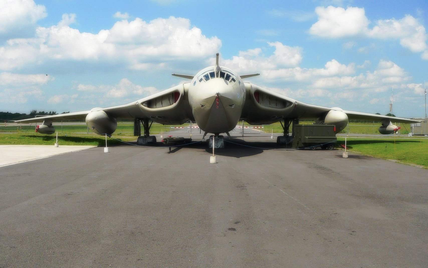
A characteristic feature of the VICTOR bomber was the complete lack of defensive weapons. It was believed that high speed and altitude to protect the bombers from enemy fighters.
In November 1952, Britain conducted its first test of a nuclear bomb. Before adopting VICTOR VOLCANO aircraft and its carrier was a bomber VALIANT that in October 1955 there was a “baptism”, dropping the serial bomb on the Australian range Woomera.
The first prototype of the VICTOR bomber (registration number WB771) crashed in July of 1954 due to flutter of the tail. The second prototype aircraft (registration number WB775) with power tail first flew on 11 September 1954. The fuselage of the bomber was painted black, and the wings and empennage remained silver. Along the fuselage passed the red bar.
Acceptance tests of the bomber began seven months later in March 1955. It was found that some characteristics (particularly, range) were lower than estimated; it was noted and lack of directional stability of the car. All identified deficiencies have been corrected in the first production VICTOR B. 1 plane. Its fuselage is lengthened to 1020 mm, which allowed to increase fuel capacity and improve directional stability, and reduced to 500 mm the height of the keel. And to solve problems related to flow of the wing and forward fuselage, installed a lot of turbulence.
The first flight of the production aircraft the VICTOR B. 1 was held on 1 February 1956, and by December, the firm Handley Page built ten production aircraft. The exhibition at Farnborough in 1956 was held the first public showing of one of these aircraft; it lacked the characteristic of all the bombers VICTOR dorsal crest in front of the keel.
Aircraft deliveries to military units for training crews began in November 1957. The formation of the first combat squadron in Cottesmore ended in the spring of 1958. The bombers began to develop ordinary air force pilots and their combat capabilities were demonstrated to the English inhabitants. During one flight the fourth production aircraft (registration number ХА921) made of salvo bombing: thirty-five high-explosive 454-kg bombs. However, the bomb Bay was designed for 48 of these bombs, but with this load VICTOR’ve ever flown.
In June 1957, the first production copy of the VICTOR bomber (ХА917) overcame in a dive the sound barrier. But soon — in August 1958 — in the connections of fuselage keel revealed corrosion, which appears usually before the fracture of materials resulting in large internal stresses — this was the reason of a ban of flights on eight planes VICTOR to replacing their tail.
To expand the combat capabilities of its strategic aviation Royal air force had planned to adopt aircraft ballistic missile, developed by the UK together with the United States. This missile received the code name SKYBOLT, or in American notation, the WS-138A. Carriers of the missile it was supposed bombers VICTOR and VOLCANO.
An order to develop media VICTOR B. 2, Vickers received in 1956. After analysis of various options for new modifications the designers chose the easiest to put on bomber turbofan turbojet Conway RCo.11 with a static thrust of 7800 kg, which was 2800 kg more than the SAPPHIRE engine modifications V. 1, and, accordingly, to increase the area of the air intakes. Everything on the machine was increased by 3000 mm wingspan — this boosted the maximum height. The rest of the design of the aircraft remained unchanged.
The first flight of VICTOR B. 2 was made on 20 January 1959. After eight months of tests, the plane crashed, but accumulated during a flight materials was sufficient for modifications of production aircraft.
The release of new modifications began in November 1961. By this time the bombers V.1 were modernized and received the system of refueling in the air with the fuel consumer boom in the forward fuselage and external fuel tanks with a capacity of 6800 litres each.
The exhibition at Farnborough 1958 pilots to pilot the VICTOR, showed its new heavy bombers the way of bombing the floor loops. This move would allow the aircraft to secretly approach a target and avoid hitting a nuclear explosion of its own bombs. VICTOR flew over the runway at an altitude of about 300 m and performed a half-loop in such a way to get above the audience in the inverted position. After that, the pilots carried out the coup and withdrew from the airfield in a shallow dive.
After the modernization of avionics equipment and equipment of electronic warfare systems for aircraft was designated VICTOR B. 1 A. development of the SKYBOLT missile was delayed, despite the fact that the US repeatedly increased funding for the program, committing to it in 1960 for $ 70 million. The emergence of the first production missile was expected only to 1965. In the interim, the British had considered adopting rocket English firm of A. V. Roe called BLUE STEEL (blue steel).
The rocket had the aerodynamic scheme “duck” and liquid rocket engine working on kerosene and hydrogen peroxide. Inertial guidance system BLUE STEEL did not have high precision due care gyroscope, and a 15-minute flight, the missile could deviate from the specified location to 500-600 m for nuclear warhead was considered quite acceptable. Range BLUE STEEL was 320-350 km, the maximum speed reached 2000 km/h.
For the carriage of BLUE STEEL had to seriously revise the VICTOR bomb Bay of the carrier and the electrical system (there are additional generators with Pelton intakes in the upper fuselage). In limbo, the rocket played for the fuselage of the aircraft, so compensation for aerodynamic wing-mounted nodules, protruding beyond the rear edge of the wing. To ensure the autonomy of the aircraft when it is operating in isolation from the base it was equipped with an auxiliary power unit driven by low-power turbojet engines.
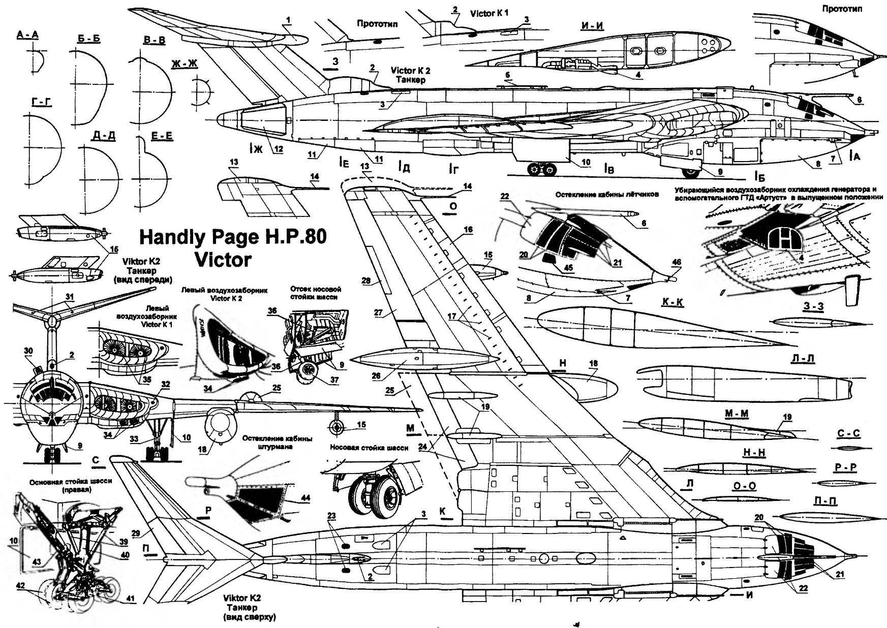
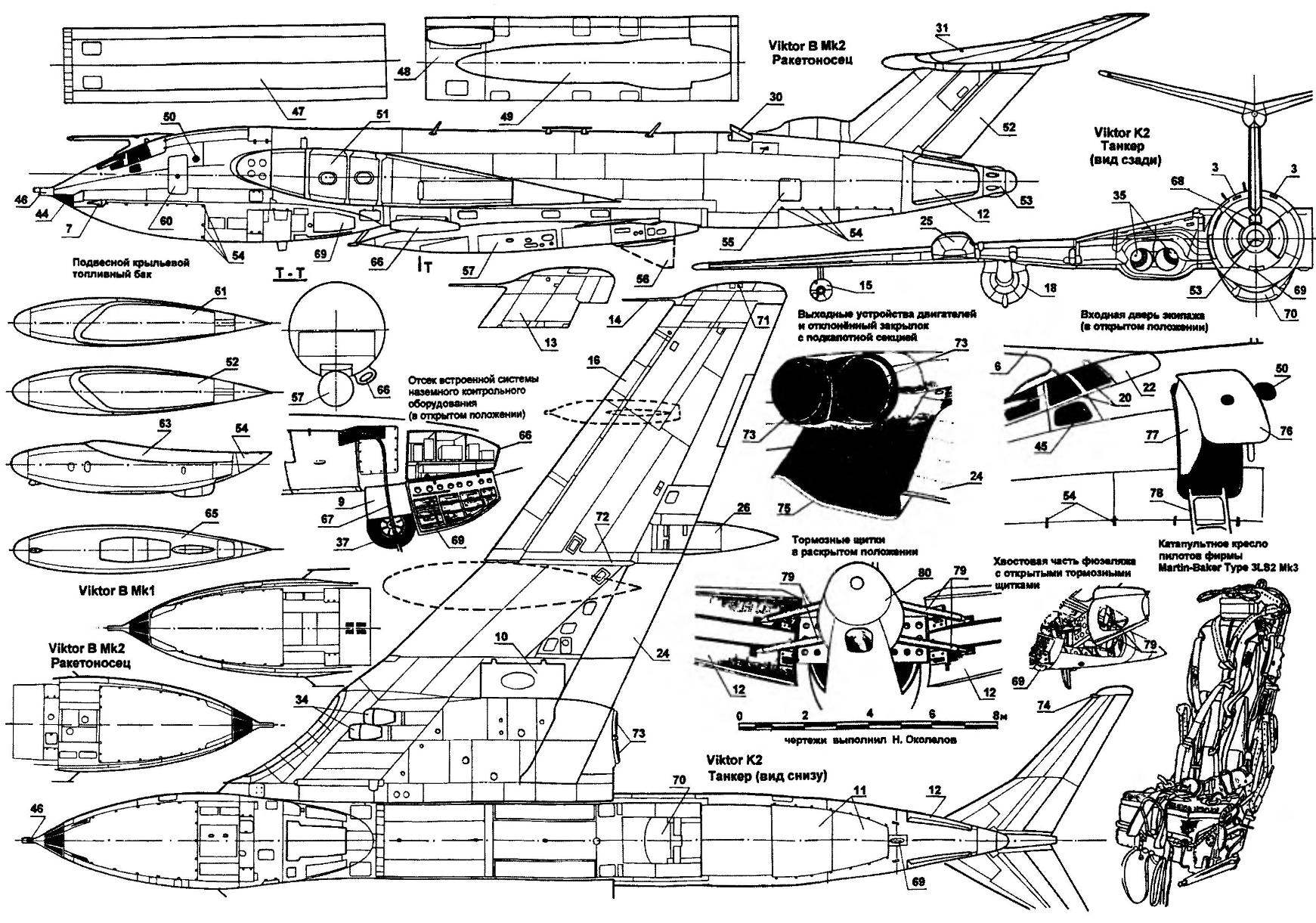
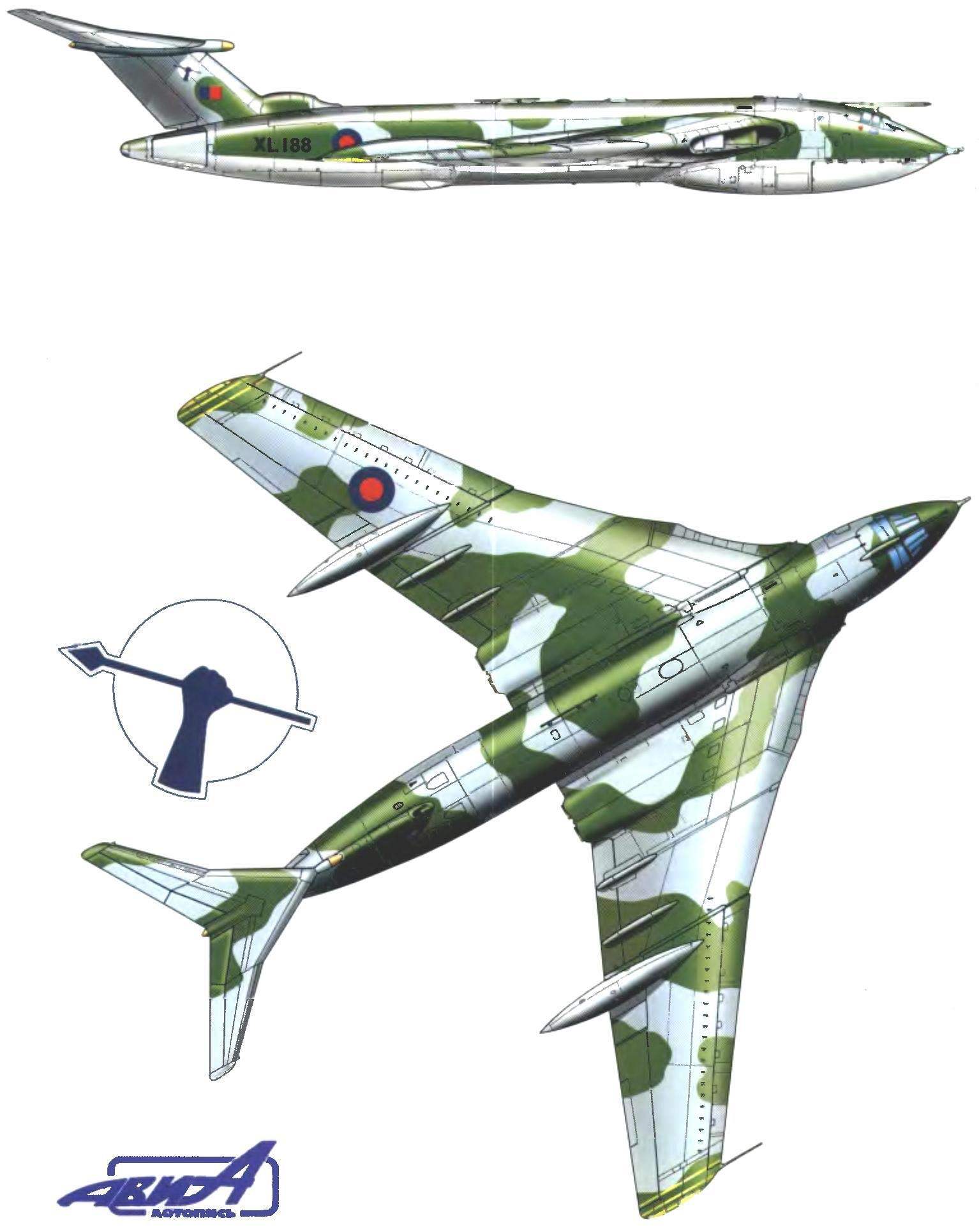
Tanker aircraft Handly Page VICTOR H. P. 80:
1 — front fairing stabilizer; 2—air intake system protivoobledinitelnoy keel; 3 — emergency windmill generator (in retracted position); 4 — retractable air-intake cooling of the generator and auxiliary GTE (in released position); 5 — the radio antenna; 6 — fuel rod system refueling in the air; 7 — air intake system, air-conditioning, 8—radiotransparent Radome compartment electronic equipment; 9 — fold niche cleaning the nose wheel; 10 — fold niche cleaning truck main landing gear; 11 —radio trim panel-rear compartment electronic equipment; 12—wing air brakes; 13 — ending wing of increased span; 14 — DWP system speed indicator; 15— wing fuel transfer system Assembly in-flight refueling Мк20В; 16 — driven toe wing; 17 — turbolator air flow; 18 — external fuel tank; 19 — fairings of flap actuators; 20—cabin Windows of prutow; 21 — windshield cockpit; 22 — manhole covers emergency evacuation of the aircraft; 23—the outlet grille exhaust air disaster chickenpox; 24—flaps in the retracted position; 25—the flaps in the released position; 26 — influx with antenna EW; 27 — Aileron; 28 trimmer Aileron; 29—steering wheel height; 30—emergency chickenpox in the released position; 31 — intake cooling system of the booster of the Elevator; 32—protivoobledinitelnoy intake system of the wing; 33 — front of the main chassis in the released position; 34—air intakes of the cooler; 35— TRD SAPHYRE 7 MK 200 (VICTOR IN MK2 — ROLLS-ROYCE 17 MK 201); 36 — cylinder retract nose landing gear; 37—wheel nose landing gear; 38 — the front landing gear; 39, the struts of the main landing gear; 40—strut main landing gear; 41 —truck chassis; a 42 — wheel nose landing gear, 43 — cylinder retract main landing gear; 44 — cabin Windows Navigator; 45 — side window; 46 receiver air pressure for the machine effort; 47 — doors of the bomb Bay of the aircraft Viktor In Mkl; 48—the bomb compartment of the aircraft IN the VICTOR MK2; 49 — hole in the bomb Bay under cruise missile BLUE STEEL Mkl; 50 — the window of the workplace radio operator; 51 root rib of the wing; 52 — rudder; 53 — tail radiotransparent Radome antenna; 54—quick release locks; 55—access door to equipment compartment; 56 — open position of the keel missiles BLUE STEEL Mkl; 57—guided cruise missile BLUE STEEL Mkl; 58 — intake cooling system compartment of the equipment; 59 — an access hatch to the compartment of the ground control complex systems of the aircraft; 60 the front door; 61 — wing external fuel tank (right); 62—wing external fuel tank (left); 63 — the wing outboard fuel tank (fuselage); 64— deviant tail fairing outboard of the tank; 65—wing external fuel tank (bottom view); 66 — compartment complex ground control of aircraft systems; 67 — the wiring ground power; 68 — cover drag chute container; 69 — tail safety wheel; 70—fuselage system fuel transfer Mk 17B; 71 — wing of ANO; 72 — panel covering the connection nodes of the console with the Central part of the wing; 73—output devices of the engine; the 74 — balance weight; 75 — the root part of the flap extending beneath the flue of the engines; 76—the door in the open position; 77 — a shield that protects the crew members during an emergency evacuation of the aircraft; 78 — input ladder; 79 — thrust deflection flaps air brakes; 80 — radiotransparent Radome
In December 1962, the US President announced the closure programme for the development of the SKYBOLT missile, and as “compensation” offered England a ballistic missile POLARIS. English bombers had lost its status as the only carrier of nuclear weapons. The VALIANT bombers were removed from service, and “Victor” is converted into tankers. With this goal in 1964 with the firm of Handley Page was contracted to rework the plane VICTOR V. 1 A. the first Six refueling aircraft with the designations 1 and VICTOR K. VICTOR K. 1A had only underwing refueling units of MK.20. In August 1965 the aircraft entered testing, during which over 18 months six aircraft VICTOR K. 1 poured 3 044 914 liters of fuel, with 10 of 646 real and training refueling contacts and participated in approximately 40 training flights over the ocean. One with a takeoff weight of 900 kg 83 could transmit in the air up to 24 000 litres of fuel. Pumps and filling units were capable of four minutes to upload to LIGHTNING interceptor tanks of 2270 litres of kerosene. This allowed the interceptor to fly nonstop to the middle East for only five hours.
Since 1964 on the “Victor” K. 1 and K. 1A, a third filling unit in the fuselage. But the weakness of the power plant the first modification of the plane was not allowed to have on Board more fuel for refueling, and since 1968, began the conversion of the tanker aircraft VICTOR B. 2. Until 1974 they had converted 24 of 34 such bombers. The other planes were reclassified in the strategic sea scouts VICTOR SR.2.
In the bomb Bay of this car was extra fuel. The main reconnaissance vehicle was a powerful airborne radar that allowed one plane for seven hours of flight to get a detailed radar map of the entire Mediterranean sea. And four scout VICTOR SR.2 can fully control all shipping in the North Atlantic.
During the Anglo-Argentine conflict, 15 of the VICTOR K. 2 tankers was provided the actions of the transport and bomber aircraft of the British. Based on ascension island, they made about 500 gas stations. By the way, the duration of one filling was 15 minutes, during which from “donor” to “recipient” shimmered with 11 tons of fuel. By VICTOR K. 2 tankers the duration of the flight refueled the aircraft reached 24 hours, and the range is 12 800 km. a VICTOR K. 2 Tankers was widely used during the Gulf war.
Currently, the aircraft decommissioned and replaced by gas modification of civil aircraft.
The description of the construction of the VICTOR bomber, the Fuselage consists of three parts — the cockpit, bomb Bay and tail section. The cabin is associated with the cylindrical portion of the fuselage, and the equipment is enclosed in a projecting cowl, the rear part of which is used to embed the nose landing gear.
The navigation for visual bombing is pointed forward fuselage in front of the radar. Big sweep Central part of the wing is allowed to position the wing box in front of the bomb Bay, which gave the opportunity to build a fuselage diameter of not more than 3000 mm.
Between the cockpit and the bomb Bay of the fuselage has a power compartment, to which are attached three of the spar and casing of the root of the wing. Planes V. 2 this compartment stands for the fuselage. The Central frame compartment, and upper and lower walls laminated, with corrugated filler. Front and rear frame compartment solid. To the rear are mounted massive forged reinforcing beams.
The rear part of the fuselage, bomb Bay and forms representing polutrusy, is attached to the power compartment. Panel to be fitted is formed by four longitudinal beams and panelling. Power set the back of the fuselage consists of C-shaped frames and stringers t-section connected to the casing by spot welding. In the field of acoustic impact from the engines used thicker plating, and modification B. 2 — double skin.
For the bomb Bay, the fuselage has a cylindrical shape with a cut from below the closed radio transparent covering, the tail portions are partition walls with the filler, which is attached to the keel. In the rear part of the fuselage are air brakes — they are allowed to open at any speed of flight, at the end of the tail section — fairing antennas EW.
A sealed cab has a very complex shape. From below it is bounded by floor, from the rear hemispherical wall and the front glazing for the Navigator-Bombardier. Floor frame consists of longitudinal beam profiles and transverse beams. Force elements connecting the floor with the bottom used as table Navigator. Under the floor is a large radiotransparent Radome made of fiberglass, and then a compartment for equipment with a boost from the oncoming flow entering through separate inlets. In order to improve the fatigue strength of the cabin is made of aluminum-copper alloy.
The upper location of the horizontal tail proved to be aerodynamically favorable: in all modes of flight, including loss of speed, the stabilizer was out of the bevel flow. Even with the loss of speed the buffeting is minor, and the management is fully effective. Interference of articulation of the stabilizer keel is reduced to a minimum. The fairing in this place mainly covers the protruding components. Since the efficiency of the keel with this arrangement of the stabilizer is increased, the height of the keel is less than under any other arrangement. On production aircraft tail height is reduced to 500 mm, compared to the prototypes. The fixed part of the stabilizer has minimum dimensions necessary for mounting hinges and placement drive the elevators. Through the use of powerful aerodynamic compensation reduced the required power and weight of the boosters. The use of boosters eliminates the danger of overbalance at low speeds.
In the aircraft design process was investigated the possibilities of using layered panels, in particular with a honeycomb core, but was rejected because at that time there was no reliable adhesives. Decided to use panels with a corrugated filler, fastened by spot welding. This measure has opened up a whole new design opportunity. A significant difference between panels with honeycomb and corrugated fillers is that the latter, having directed a placeholder that can take large compressive loads. This allows you to design with better weight output than panels with honeycomb core.
Main power components the root of the wing in front. Three of the spar beam with the cutout for the air channel together with the panels perceive virtually all the loads on the wing, and pass it to three-wall power section of the fuselage. For compartments, the engines, closer to the console, there are two reinforced ribs, one of which has a wall with a filler, and an intermediate aperture with a filler. These elements perceive the load of the chassis and transfer them to the spar and the skin.
English tanker aircraft HANDLEY PAGE VICTOR K. 2 of No. 55 squadron
The location of engine compartments for the main power elements significantly reduces the risk associated with fire or destruction of the turbine, and also simplifies the operation of the engine and facilitates their replacement on a more powerful.
The root part of the wing consists of three casings, the casing of which is working on the compression of the corrugated filler, which makes the spar easier. Managed socks deviate for one second by means of compressed air supplied from cylinders, and cannot be removed until the cylinders will not be re-charged. They are rejected simultaneously with the flaps or automatically when the lift coefficient of the su exceeds the specified value. The moment this is detected by a sensor associated with two holes on the wing and the receiver is full of air pressure. At high speeds the sensor number M, the system deviation socks wing off.
The design of the sock has a wing anti-icing system. Hot air is passed not through the corrugation, as this would require very large flow of air, and the special grooves. The leading edge of significant thickness and it progressirovanii grooves directed along the chord. On a thick sheet is fixed on top of a thin sheet of paneling. These Luts plating reinforced corrugated, which managed the sock is attached to the longerons and stringers.
Airplanes V. 1 flaps and ailerons — conventional design. Airplanes B. 2 trim Aileron backed by corrugated.
The keel has a three-wall caisson, the design of which is similar to the design of the wing. There is also applied the covering with corrugated filler. The leading edge is provided with grooves for the passage of hot air. The keel connects to the fuselage is almost the same as the wing.
The horizontal stabilizer consists of two spars, three ribs, several stringers and the hull with a directed along the span corrugated filler. The toe of the stabilizer has channels for hot air. Covering its backed corrugated. The rudder has three hinges and two longitudinal members. The covering is reinforced corrugated directed along the chord. The axis of the hinges of the Elevator passes through the 1/3 of the chords. In the plane of the joints is the main spar; the front and rear spars are of lightweight design. End portion of the rudder for balance weights have four ribs and the usual trim.
Landing gear differs by high reliability and relatively low weight, constituting only three percent of the takeoff weight of the aircraft. Bow front with two wheels can freely navigate in the range of 175 degrees and is rotated by the hydraulic actuator within 90 degrees.
Turbojet engine firm Rolls-Royce “Conway” mounted on a light arched wall behind the spar. When mounting them raise bomb hoist, which is mounted on the wing. Panel wing under the engines can be removed without special tools. The intakes are siding with a corrugated filler. They are connected to the intake of each engine cylinder channel (the trim with filler). In the Central part of the right wing on the plane V. 2 installed auxiliary power unit.
Control a fully powered, fully redundant. Control scheme is such that half of the Elevator or one Aileron working in case of failure of the other half of the rudder or Aileron. Duplicate everything except ball jacks, hydraulic motors and control rods. The drive surfaces is compact electrohydromechanical units through rocking. The efforts of the pilot acting on the control levers, are transmitted to a mechanical system. Control knob connected with the machine, outstanding effort, proportional to velocity head and compression of the spring.
Airplanes V. 1 was installed yaw damper. Due to the increase in altitude on the plane V. 2 is mounted yaw damper and transverse vibrations. In both cases, a machine trim programming, eliminating the tendency to dive. The hydraulic system of the aircraft serving eight consumers: gear, flaps, controllable socks, air brakes, flaps bomb Bay, wheel brakes, nose landing gear and the plane V. 2 — the emergency air intakes chickenpox. Vulnerable parts of each chain are duplicated.
Cold air for air conditioning system in the cabin and for pressurization of the equipment compartment under the cabin floor, enters through intakes in front of the cockpit. Hot high pressure air for air conditioning systems and de-icing is taken from the compressors of all four engines. Cold air enters the equipment compartment through the fan. Outboard air flowing under the action of dynamic pressure, passes through the heat exchanger in an air conditioning system.
In the systems de-icing of wing, tail, sock fin, bomb Bay and Pitot installed in the forward fuselage, also used air. The exhaust air is vented to atmosphere through holes in the upper wing skin and at the ends of the feathers. Although the intakes are partially heated by hot air flowing through the corrugations of the filler, protivoallergennye the leading edges of the flow divider is provided by cyclic elektroobogrevatelem. The same way it is protected from icing over-ending wing aircraft V. 2.
The fuel is placed in wing and fuselage. Provides suspension under-wing fuel tanks. The fuel system is equipped with a machine providing the sequence generation fuel from the tanks that allows you to maintain alignment within the prescribed limits. Fitting fuel pressure is at the root of the left wing.
On the plane Q. 2 there are four generator AC voltage of 200 V and 400 Hz-driven engines. DC 28 V is obtained using a transformer-rectifiers. Three-phase voltage of 115V and frequency of 400 Hz for radio equipment and widely applied in the plane of the magnetic amplifiers from conventional transformers. To obtain a voltage of 115 V and frequency of 1600 Hz for radio and radar equipment used Converter.
The emergency source of power is generator three phase AC voltage of 200 V and 400 Hz driven by an auxiliary gas turbine engine. Spare power source for the control system used to start the auxiliary power unit, are two retractable windmill in the rear of the fuselage with generators three phase voltage of 200 V and a frequency of 360 Hz, each of which independently feeds the half of the duplicated control. The spare DC source are two batteries.
Flight characteristics of the bomber VICTOR B. 2
Wingspan, mm……………………..36 580
The length of the plane, mm………………….35 020
Aircraft height, mm…………………..9180
Wing area, m2 …………………..223,51
Swipe of the tail, mm…. 9950
Wheel base, mm…………………………..7470
Wheel track, mm…………………………..988
The sweep angles, deg.:
wing………………………..52,2; 44,3; 35,2
stabilizer…………………………..59,6
keel………………………………………….48,2
Relative thickness,%.:
the root of the wing…………………..16
the middle part of the wing……………………..9
cantilever part of the wing…………………6
the horizontal tail……….12,21
rudder…………………………………..9
keel……………………………..10,54—11,58
The flap deflection, deg.:
for takeoff……………………………………19
for planting…………………………………35
the deviation of the sock wing…………….23,5
The size of the tires of the wheels, mm:
the main trucks (16 PCs.)……686 x 165
the bow stands (2 PCs)……….762 x 229
The pressure in the landing gear, ATM.:
main……………………………………..175
nasal……………………………………….70
Weight, kg:
empty………………………………….41 277
maximum takeoff……….105 687
Maximum speed, km/h
at a height of 12 190 m…………………..1030
Ceiling, m………………………………..16 765
Combat radius of action, km………..3701
N. Food reserve was, A. CHECHIN
Recommend to read
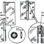 THE HOUSE DOORS CREAKING…
You can, of course, brush them, however this will not last long. More radical means of plastic washer embedded between the half-loops. There is another way to get rid of the squeak....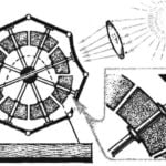 THE SUN IN HARNESS
The intricate design shown in the picture, — not that other, as the solar engine, the engine that converts the thermal energy of sunlight directly into mechanical work. It is arranged...
