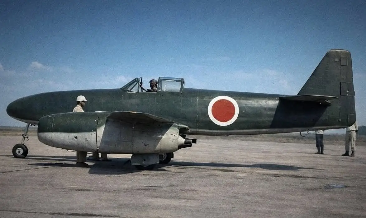
Work on jet engines was already under way in Japan before the start of World War II, although at first it was mainly exploratory in nature. Active interest in jet technology arose when Captain N. T. Tanegashima became head of the engine department at the Naval Aviation Arsenal in Yokosuka (an organization similar in status to a research institute). He regarded the development of a turboprop engine as a priority, but after consultations in 1938 with Professor F. Numashiho, a well-known Japanese specialist in axial compressors, he changed his mind and turned to turbojet engines (TJEs).
The first experimental motor, TR-10, had a single-stage centrifugal compressor and a single-stage axial turbine. It was created on the basis of a large turbocharger for boosting a piston engine. This engine was first run in the summer of 1943, but its efficiency left much to be desired.
The Ne-10 TJE was already fitted with a four-stage axial compressor. On its basis they created the Ne-12 engine and its lightened version, the Ne-12B. In all, 40 such motors were built for the Kikka fighter under development.
Under the German–Japanese cooperation agreement, a Japanese military attaché attended a demonstration of the Me 262 jet aircraft. In 1944 diplomats requested information, samples of equipment, and permission to send Japanese specialists to Germany. The Japanese wanted to purchase a license for the Me 262A-1a, the Me 163B-1a rocket interceptor, and for their powerplants, armament, and other equipment. In the summer of 1944 the German Air Ministry issued an order to transfer copies of drawings, various documentation, and equipment samples to Japanese representatives. These were to be delivered to Japan aboard several submarines. But only one Japanese submarine, I-29, reached Germany. There was no room on it for the paid-for Me 163 and Me 262 aircraft; nevertheless it was loaded with an HWK 509 rocket engine, a BMW 003 turbojet, and other examples of the latest weaponry (a dismantled V-1 flying bomb, gyroscopes, blocks of the latest air-defense radar and torpedo homing systems), as well as about 10 tons of strategic materials.
On 16 April 1944, Lieutenant Commander–engineer Eiichi Iwaya left Germany for Japan aboard I-29. After 87 days at sea he landed in Singapore and from there flew to Japan. The main set of documentation on the German jet engines and their full-scale samples remained on the boat and were permanently lost when it was sunk west of the Philippines. The Japanese obtained only copies of general-arrangement drawings of the BMW 003A engine that Iwaya had kept with him. His return coincided with preparations for series production of the Ne-12B. But even from what he brought, it was clear that the BMW 003A was more promising than the Japanese motor.
From fragmentary German documentation, projects were drawn up for the Ishikawajima-Shibaura Ne-130, Nakajima Ne-230, and Mitsubishi Ne-330 engines. Later the Naval Aviation Arsenal in Yokosuka developed its own version of the BMW engine, designated Ne-20. The Japanese motor turned out to be about a quarter more compact.
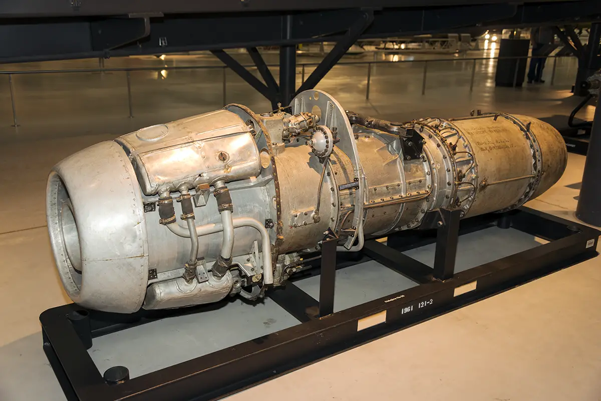
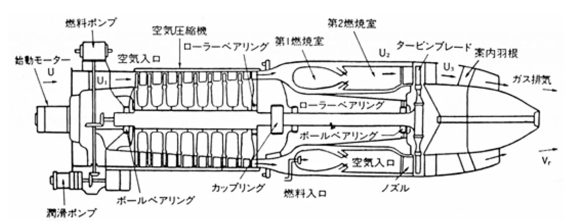
Design of the Ne-20 was completed at the end of January 1945, and preparations for its series production began. The first bench run of the engine took place on 26 March 1945.
Development of the Ne-20 engine was led by Captain Nagano, with Captain Tanegashima seconded to him. The production section was moved to Haneda at the southern foot of the Tanzawa mountains, where the threat of American air attack was smaller.
At first the turbojet compressor did not provide a sufficient pressure ratio. Nagano believed that the stator blades with a Clark Y profile were insufficiently curved, so he further bent them with a hammer and anvil. The modified stator was tested on the second Ne-20 specimen. The result was positive, so all remaining engines received modernized compressors. Another problem was frequent overheating and failure of the compressor shaft’s radial bearing, but these shortcomings were also eliminated. Because of cracks at the blade attachments in the disk after two hours of engine operation, the blades had to be thickened and their number reduced. Engine thrust decreased, but reliable running time was increased to five hours.
It was already mid-June 1945, and production of the Ne-20 and its trials on the Kikka aircraft were only beginning. The arsenal in Yokosuka, renamed the First Technical Arsenal in February 1945, assembled nine Ne-20s. A shipyard in the same Yokosuka produced another twelve motors, but they were of low quality.
By that time Nakajima’s chief designer, Kenichi Matsumura, had completed design of the Kikka aircraft. He took the twin-engine overall layout from the Me 262, but otherwise the Japanese design was entirely original.
At first the aircraft was intended solely for “special attacks” (the coded designation for kamikaze). According to the specification it had no undercarriage and was to take off from a trolley using rocket boosters.
The aircraft design was ready at the end of October 1944. By November the Navy promised to test the Ne-12B engine on a G4M flying laboratory and begin deliveries. It was expected that by the end of December 1944 Nakajima would produce 40 aircraft for “special attacks.”
The firm tried to meet all assigned tasks on schedule. Despite the haste, basic wind-tunnel model tests were carried out. In the process a dangerous phenomenon was unexpectedly discovered. At about 200 km/h, with the slightest increase in angle of attack, violent flow separation occurred on the outer portions of the wing. This may have been related to the use of laminar airfoils. To eliminate the effect, a kind of fixed slat was made near the leading edge—a profiled slot through which air flowed from the lower surface to the upper. The idea was probably borrowed from the German Me 163 fighter.
According to the schedule, the airframe intended for static tests was to be built by the end of February 1945. But even before the first prototype was built, the Navy changed its requirements. Under the new specification the aircraft was to have undercarriage and means of saving the pilot. Naval command decided that, thanks to the high speed they hoped to achieve, it would be possible to create a machine capable of penetrating a naval formation’s air defenses and striking the “principal” ship with a 500 kg armor-piercing bomb or a Type 91 torpedo (800 kg). It was also planned to install two 30 mm cannons with a small ammunition load. The kamikaze aircraft began to turn into a full-fledged fighter-bomber. It was then that its coded designation Kikka (“Orange Blossom”) first appeared.
In early January 1945 another meeting was held on the state of Japanese military industry, which also dealt with the Kikka aircraft. Powerplant questions were discussed. Overall preference was given to the new Ne-20s, but for the first flights the Ne-12B was to be used, as it was more fully developed.
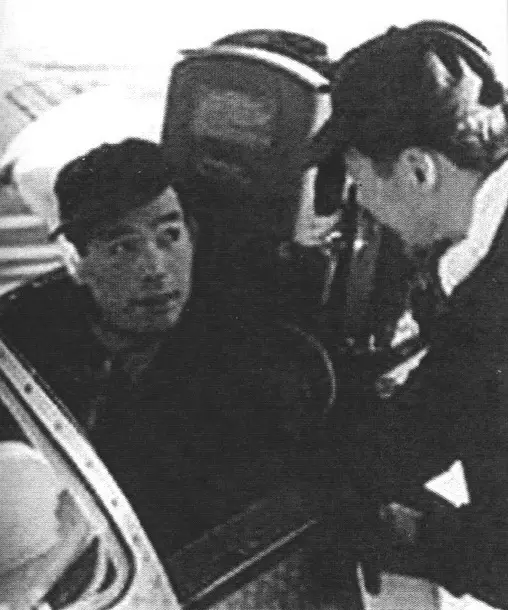
There was no very great difference in the fighter’s structure compared with the suicide aircraft. Apart from the added undercarriage, the fuselage, designed for fixed armament, and the cockpit glazing changed somewhat. On 10 February 1945 the wooden mock-up was formally accepted and approved, with pilot Susumu Takaoka present. Immediately afterward preparations for series production began. The first and second prototypes were not to carry armament.
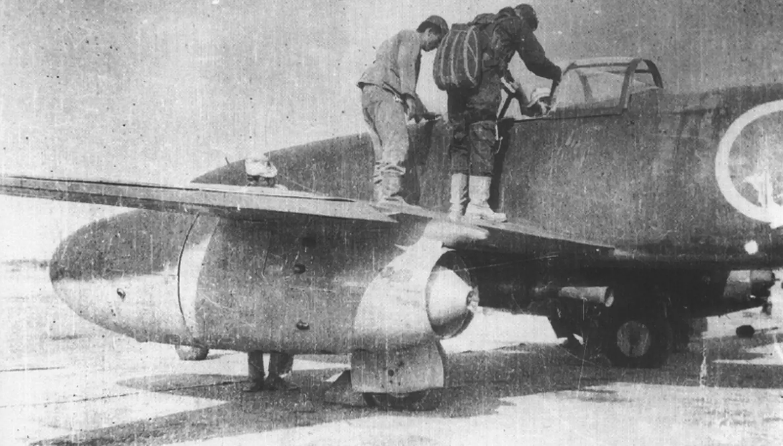
Because of increasingly frequent American raids, the designers had to move from Koizumi near Tokyo to the city of Sano in the east of the country. Production also had to be dispersed. By then the mid and rear fuselage sections, wings, and empennage had been made in Yokosuka; smaller parts were produced at Nakajima in Koizumi. Part of the production capacity was moved into buildings of a former silk-processing factory in Gunma Prefecture.
In March it was decided to use Ne-20 engines on the first Kikka aircraft. By May 1945 there were already six flightworthy Ne-20 engines, and hopes for starting aircraft production rose considerably.
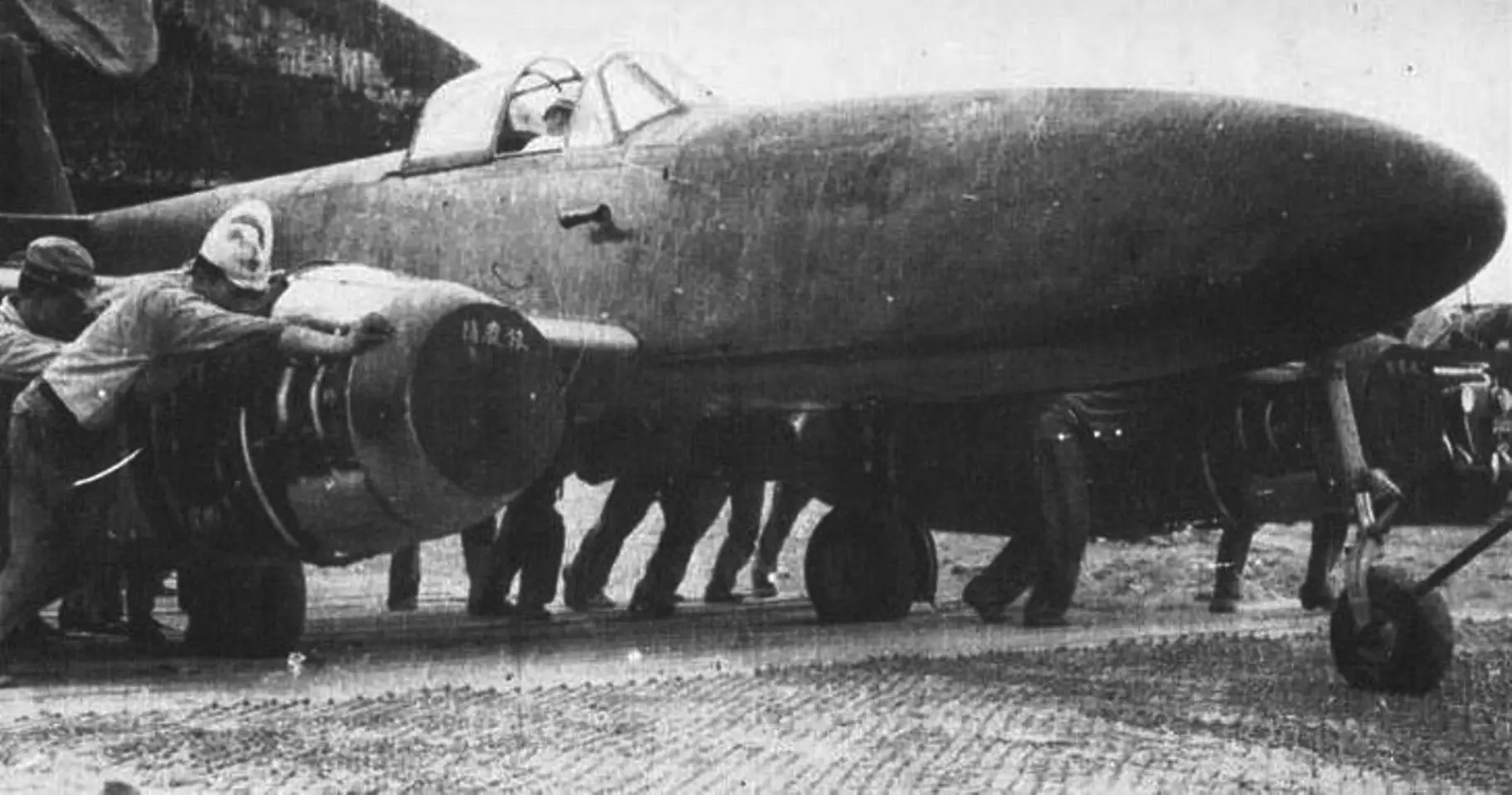
The first Kikka was delivered to the Koizumi plant for engine installation on 25 June 1945. On 29 June it was declared fit to fly, but the runway was too short, so trials were moved to Kisarazu air base on the shore of Tokyo Bay.
On 27 July Lieutenant Wada began the first taxi runs. On 29 July he accelerated the aircraft to 130 km/h to check the wheel brakes. When the last ground tests finished on 6 August, rumors appeared of a powerful explosion that had destroyed the city of Hiroshima. Detailed information was withheld.
On 7 August the machine was prepared for its first flight. Lieutenant Takaoka started the engines, taxied to the far end of the runway, and extended the flaps. He brought engine speed up to 11,000 rpm and began the takeoff run. 725 meters from the start the aircraft left the ground. The pilot was surprised by the low noise level and the absence of vibration. Takaoka circled over Tokyo Bay. Airspeed kept increasing, so he slowly reduced engine rpm, because on the first flight the undercarriage remained extended. Controllability proved satisfactory, but the pilot had to be careful, keeping engine speed no lower than 6,000 rpm so the engines would not stop. The approach to the airfield was therefore long and shallow. Finally he extended the flaps and made a soft landing. The entire flight lasted 11 minutes.
The first successful sortie made it possible to begin full-scale trials. The second flight was scheduled for 10 August; senior army and navy officers were invited. However, because of continuous American air attacks on Tokyo and its surroundings, the tests were postponed to the next day.
On 11 August the weather was good, though a strong crosswind was blowing. For greater effect additional rocket boosters were fitted to the aircraft. On the fourth second of takeoff Takaoka ignited the boosters. They produced such intense acceleration that the aircraft’s nose pitched up sharply and the fuselage skid scraped the runway. The pilot pushed the stick forward; the nosewheel hit the concrete, and at that moment the rocket boosters burned out. The pilot thought both Ne-20 engines had failed and decided to abort the takeoff. At that time Kikka was moving at 167 km/h and had already covered roughly half the runway. Takaoka began braking, but the ineffective brakes could not slow the run. The machine began to deviate dangerously from the heading, rolled onto the grass, and entered a drainage ditch around the airfield perimeter. It then slid on its belly some distance farther—the landing gear struts tore off—and stopped. The pilot jumped from the cockpit. There was neither fire nor explosion, but it was already clear that this aircraft would never fly again. Even if its test flight had succeeded, it would already have meant little, because Japan soon surrendered.
In August 1945, 25 Kikka aircraft were under construction, including five two-seat trainers. A two-seat research variant was also being prepared, to be followed by a single-seat fighter armed with a pair of 30 mm cannons. According to plans, mass production of Kikka was to begin at several plants in September 1945, but those plans were not to be fulfilled—“Orange Blossom” never opened.
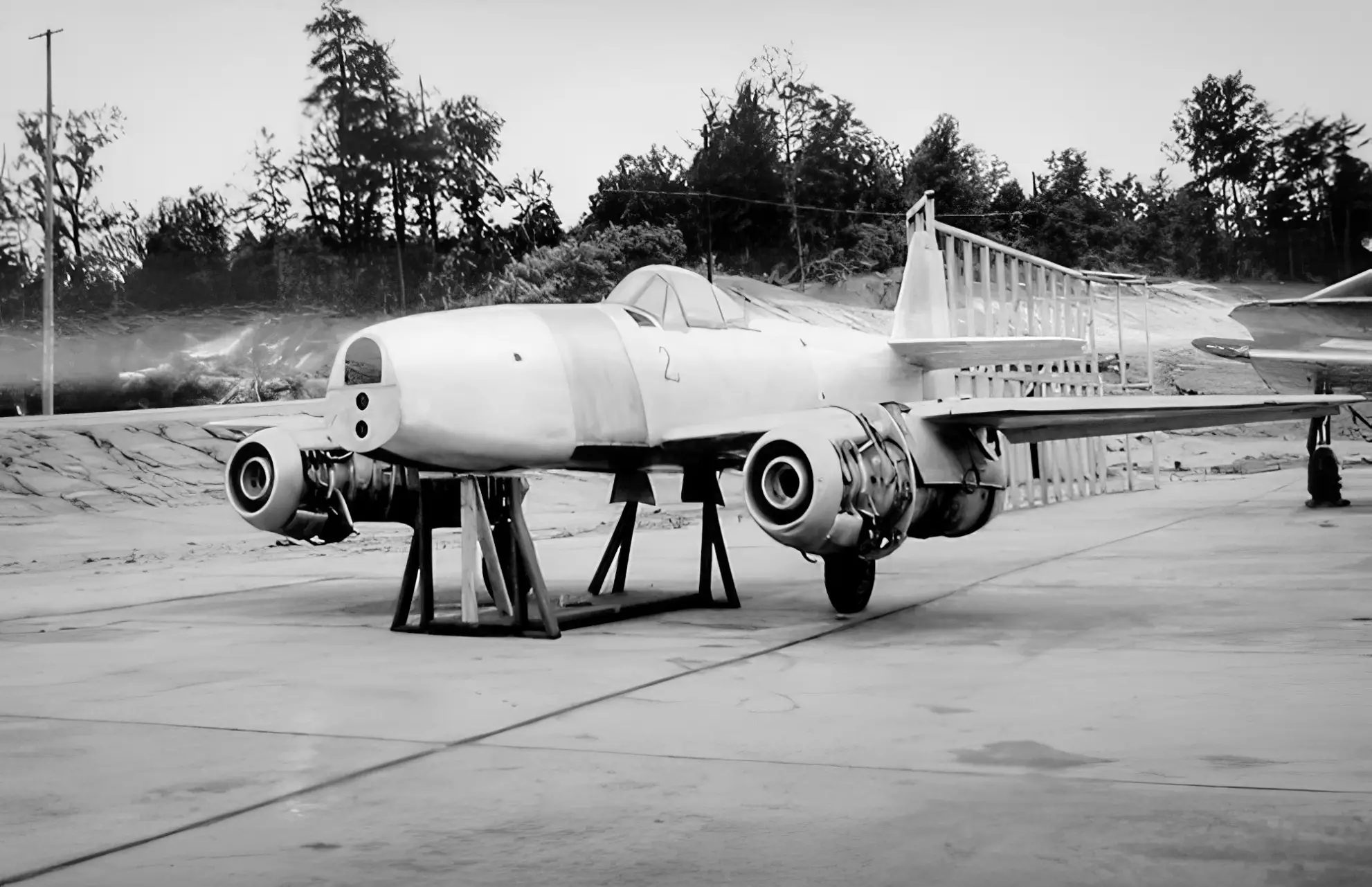
American occupation forces showed little special interest in Japan’s jet pioneer, since it had no advantages over piston aircraft of the period. Nevertheless, at least three Kikkas were shipped to the United States. One of the surviving machines was later repaired, fitted with surviving original engines, and displayed at the National Air and Space Museum of the United States.
Technical data of the Nakajima Kikka (estimated)
| Wingspan, m | 10.00 |
| Length, m | 9.25 |
| Height, m | 3.05 |
| Empty weight, kg | 2300 |
| Normal takeoff weight, kg | 3550 |
| Maximum takeoff weight, kg | 4312 |
| Maximum speed, km/h: | |
| at sea level | 623 |
| at 6000 m | 680 |
| at 10,000 m | 697 |
| Service ceiling, m | 10,700–12,000 |
| Range, km | 950 |
Technical description
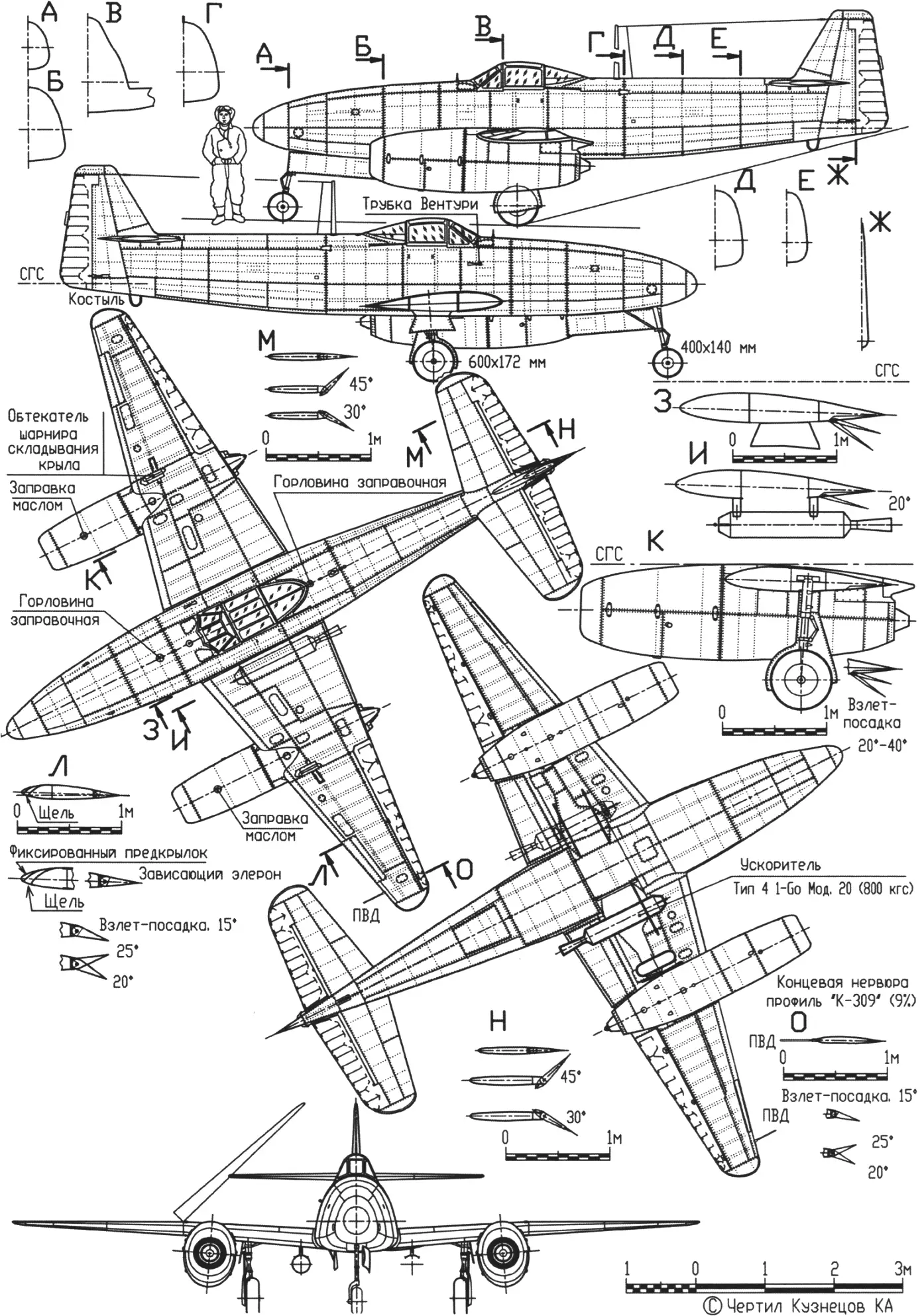
The Nakajima Kikka is a single-seat twin-engine jet aircraft built as a low-wing monoplane with a conventional empennage and retractable undercarriage.
The fuselage is of triangular cross-section with rounded corners, of monocoque construction, and is technologically divided into three parts. The forward section is entirely of duralumin, with attachments for the nose-gear hinges. The center section, of duralumin and steel parts, is built as a single unit with the wing center section. The rear fuselage, combined with the fin, is made of aluminum alloys.
The cockpit is fitted with standard instruments. The canopy consists of three parts; its center section slides aft to provide access. Fuel tanks are installed in the fuselage ahead of and behind the cockpit.
The wing is of two-spar construction with 13° sweep on the leading edge; the incidence is 2° at the root and zero at the tips. The airfoil is a laminar Nakajima section (K-125 at the root transitioning to K-309 at the tips). Both duralumin and steel were used in construction. The wing has flaps that deploy to 20° for takeoff and 40° for landing, and ailerons that deflected with the flaps on takeoff and landing. The outer wing panels could fold to ease stowage in underground shelters.
The empennage is of duralumin construction; the aerodynamically balanced control surfaces are fabric-covered. The rudder has a trim tab bent on the ground.
The undercarriage has three struts with hydraulic shock absorption. The main wheels, 600 × 172 mm, from the A6M fighter, including brakes, retract into the wing toward the fuselage. The nosewheel, 400 × 140 mm, retracts aft into the fuselage. An auxiliary skid is fitted under the rear fuselage.
The powerplant comprises two Nensho Ne-20 turbojets with takeoff thrust of 4.7 to 5 kN (479…510 kgf) each. The engine has an eight-stage axial compressor, an annular combustion chamber with injectors, and a single-stage axial turbine. Engine length is 2750 mm, maximum diameter 620 mm, weight 450 kg. Because nickel was unavailable, the turbine blades were made of manganese–chromium–vanadium steel. Hourly fuel consumption was 730 to 740 kg/h. Two fuel tanks totaling 725 L were fitted. Oil tanks formed part of the powerplant.
“Modelist-Konstruktor” No. 7’2025, Dmitry KUZNETSOV
Recommend to read
 THE CAR LEARNS TO SWIM
Among the huge variety of all-terrain vehicles of particular interest is the class of floating cars-amphibians. They are irreplaceable for geologists, exploration expeditions, the... CRUISE RADIO-UNIVERSAL
For those who have passed the first stage of learning the art of radiopilot on the simplest gliders and pondered the project of the first motor cars will probably be interesting and...
