From the beginning of 1960-ies wig designers engaged Taganrog OKB G. M. Beriev. From made in the Taganrog scientific-research works, it should be noted the collection of very large wig, which is designed under the guidance of A. G. Bogatyrev, and the project of wig-aircraft carrier.
Be-1 for erratic chassis.
On that subject, since 1963, the Institute held a series of experimental studies on the configurations of wig catamaran type hydrofoil. For dvuhlodochnaya scheme was chosen several options hydrofoils on the so-called four-point scheme.
In the first variant, the designation “A”, nasal underwater wings were located ahead of the center of mass, forage for him. Unlike hydrofoils, the mode of movement of hydroeconomy is characterized in that at high speeds the weight of the apparatus is balanced by the nose like an underwater wing, and the aerodynamic lift force created by the supporting surface of small aspect ratio. Your contribution makes a dynamic air cushion.
To fully simulate this mode of movement in hydraulic canals TSAGI was impossible, so the test was divided into three stages.
The first of them was conducted towing tests in the testing tank are proposed pool TSAGI at speeds to 12 m/s. Their goal was the selection circuit hydrofoils. Then experienced a large-scale model towed in open water at speeds up to 20 m/s.
The final stage of testing was to manufacture a self-propelled scale model airplane-the aircraft carrier and her research on the adopted scheme of the hydrofoils, as well as controllability, stability and seaworthiness.
Be-1 “Hydrolat”:
1 — the cockpit canopy; 2 — antenna coherent radio; 3 — turbojet engine With М701-250; 4 — vertical tail; 5 — water rudder; 6 — feed the hydrofoil; 7 — washer-wing; 8 — wheel main landing erratic chassis; 9 — float; 10 — front scuba wing; 11 — wheel of the nasal support erratic chassis; 12 — carrier; 13 — Aileron; 14 — flap-flap.
Research in TSAGI was conducted on two models – the first in the scale of 1:7 (6313) and the second in the scale of 1:4 (model 6320). Linking the past and served as a base for the manufacture of a manned model, the construction of which instructed the OKB G. M. Beriev. This working model in use, the OKB called “Hydroleca”, and in official documents – the be-1.
Be-1 afloat.
Hydrolat was developed by the initiative group of young designers. It was made almost entirely of wood and had a powerplant consisting of Czechoslovakian turbojet engine М701-250.
At the trial, held in the waters of the Gulf of Taganrog in June-October 1965, test pilot YM Kupriyanov developed on hydrolite speed of 160 km/h.
All there were 16 exits into the sea. Eight runs were carried out in displacement mode, forty – hydrofoil, forty-three hydrofoil and air wing with a deflected 20 – 25° of flaps. Front underwater wings at an angle of 4 degrees, aft – zero. Before the second exit to the sea hind wings are mounted with an angle of 2°, but this is not justified, and they were returned to the original position. The tests were conducted in calm and wave height of about 0.4 m.
Be-1 hydrofoil.
Testers noted that the strong jet of water coming from the floats in intercase space, creating the impression that hydrolat out of the water thanks to them, and not underwater wings.
To reduce the gap between the rear edge of the wing and the water surface was almost doubled the chord of the flap of the wing, which significantly increased lift created by the wing.
The total lifting force created by such a device can be divided into three components: the hydrodynamic force from the underwater wings, the aerodynamic lifting force the bearing surface and the dynamic air cushion that is formed due to the deceleration of the incoming flow in the volume bounded by the wing with deflected flaps, and side floats. The hydrofoils and aerodynamic bearing surface accounted for 60%, although the calculation of the engine thrust should be enough for the withdrawal of Be-1 on the screen of the flight in which underwater wings would not be involved.
On the basis of works on Be-1, the OKB G. M. Beriev was studied the draft a 100-seat passenger gidroenergoprom Be-11. We studied the options for the installation of two turboprop engines AI-20 and four piston М337, or the same number of turbojet engines NK-7. Further, preliminary calculations of the work for this project did not go.
Like any seaplane tailless scheme for control channels of pitch and roll was used elevons, and to control the rate – rudders. At the same time for manoeuvring afloat there was a water wheel, kinematically associated with the aerodynamic rudder.
ZABLOTSKY A. A. SALNIKOV
Recommend to read TRACTOR “HUMMINGBRI” A thrifty owner, especially a rural resident, does not have too much household equipment. So I got another mini tractor. As usual - homemade (you can see about my previous work in “M-K”... VAZ-2118 “the guelder-rose” A new family of cars VAZ-2118 "the guelder-rose" is only the third in 35 years of existence, the Volga automobile plant — after "penny" VAZ-2101 and "chisel" VAZ-2108/2109 — really new,... 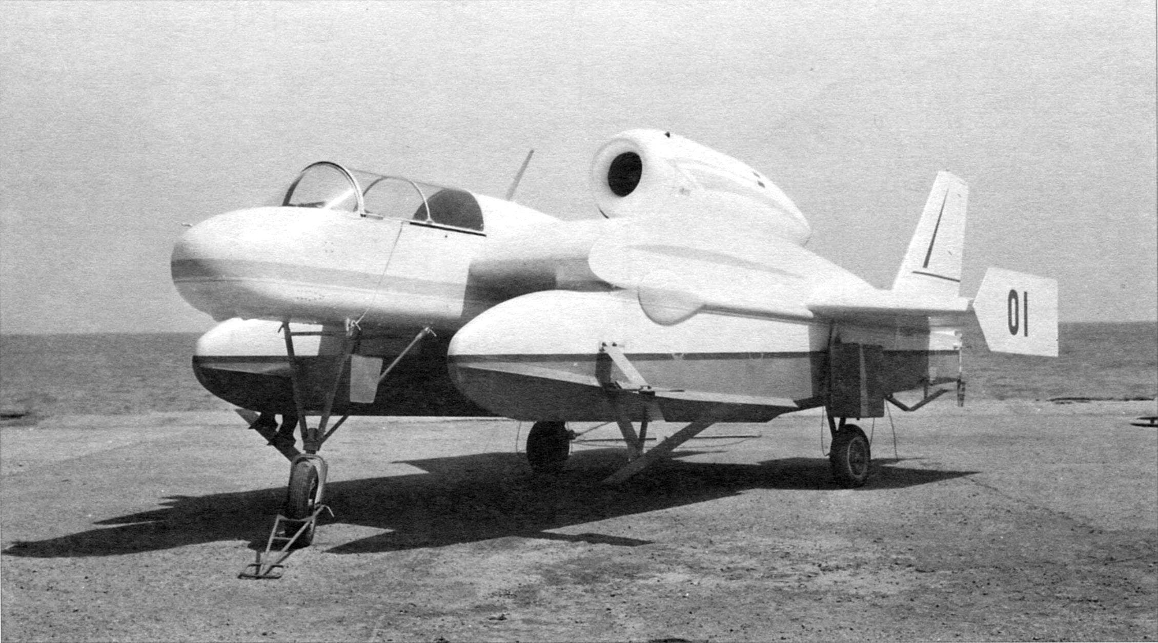
 From the very beginning of the history of water transport designers and engineers sought to give the courts the ability to move with the greatest speed. It was necessary to reduce the hydrodynamic resistance of the hull. The race for “Ghost of speed” led to the most radical solution -to completely eliminate contact of the hull with the water surface! This was made possible thanks to the creation of wig – the courts break the wings.