
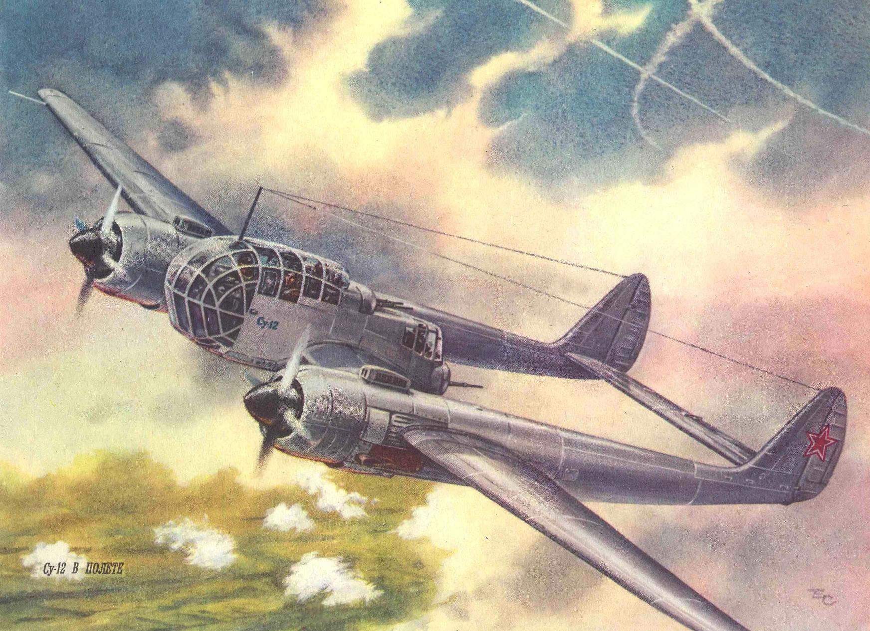
 …1947. Air parade in Tushino. Thousands of viewers saw a new, unusual and, moreover, the plane. It was a monoplane su-12 (RK), constructed under the direction of P. O. Sukhoi. It was intended for artillery fire adjustment and exploration at any time of the day.
The aircraft was designed in a short time. Its development began in mid-1946, and in August following su-12 were built and began to undergo factory tests
What was this scout-spotter?
Aircraft of this design were called “flying frame”. Two-beam scheme is provided to the crew especially a good review.
The WING of the su-12 consisted of a fixed center section (with two pods) and two consoles. The single-spar design, with working a metal shell (thickness 0.6 — 1.0 mm). The spar was located at 40% chord and passed through the cockpit. In addition to the main spar, had a sub to the front and rear. Cross set of the wing — plate of ribs. To the rear spar was fastened the flaps and ailerons are supplied with weight and aerodynamic compensation. The latter had a metal frame (of the channel-section spar and pressed ribs) covered with canvas. On the left Aileron was operated trimmer, and on the right — servo tab. Between the engine nacelles and ailerons mounted brake flaps.
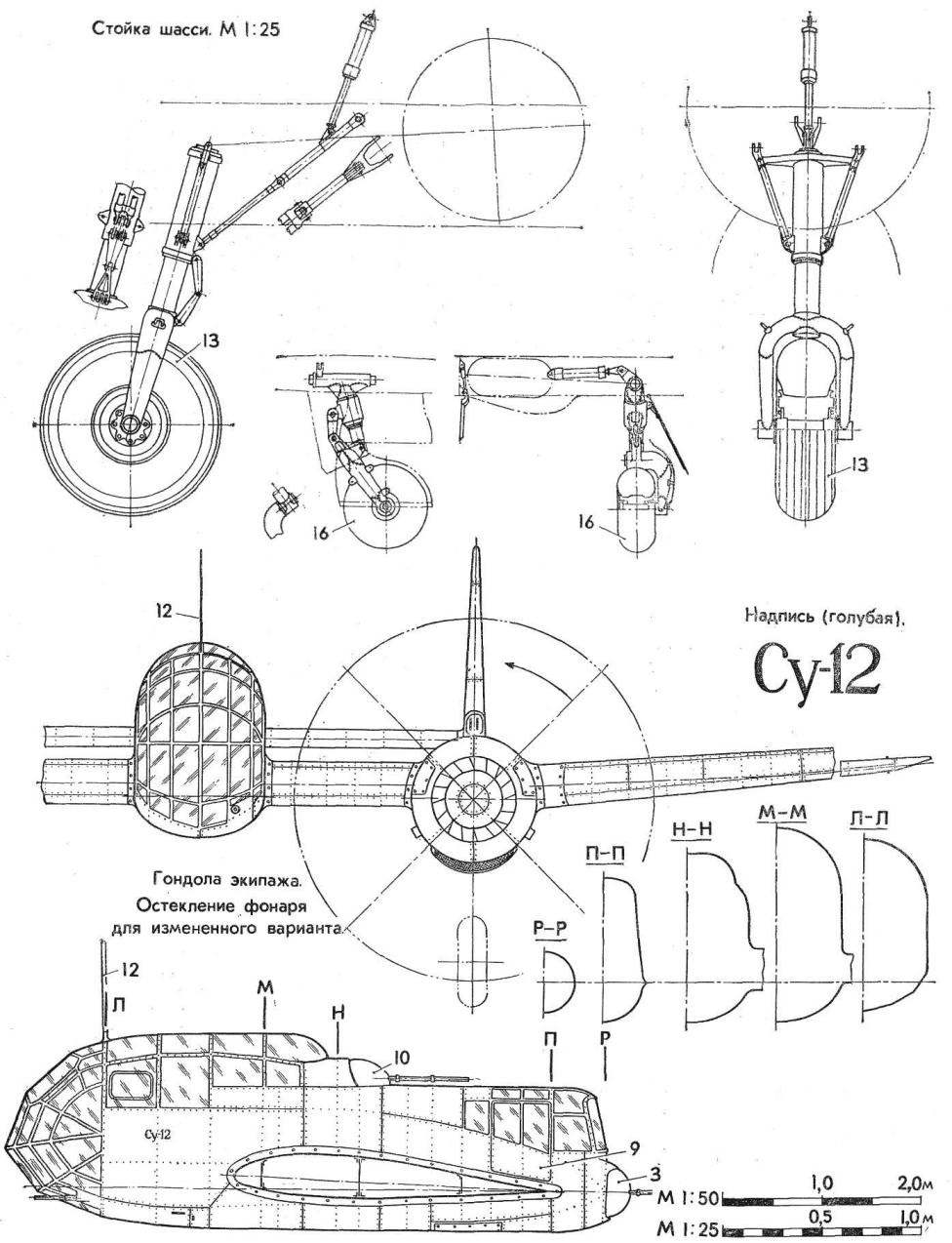
The GONDOLA CREW, consisting of front and rear cabs, to improve visibility has been glazed front and top. The original top was used spherical glazing, the amended version was flat. The bottom front of the cab was protected by the bulletproof glass thickness of 15 mm. To the front cockpit, the crew members climbed through the lower hatch and back through the door on the left side of the gondola. In the event of unforeseen circumstances, the designers have provided mechanisms for emergency release doors and a hatch and in front of the cabin, in addition, — additional top hatch.
The TAIL boom was a continuation of the nacelle. Each was a frame monocoque structure with duralumin covering.
The KEELS of the VERTICAL STABILIZER with a frame of stringers and ribs structurally of one piece with the tail boom. The dural tail; the Elevator and rudders were trimmed with cloth and had the weight and aerodynamic compensation. The rudders were installed operated trimmers, Elevator — operated trimmer and servo tab. Between the tail boom was located dvuhkonturniy stabilizer.
CHASSIS normal scheme with a tail wheel. Main legs retracted into the nacelle, the tail wheel — in stabilizer.
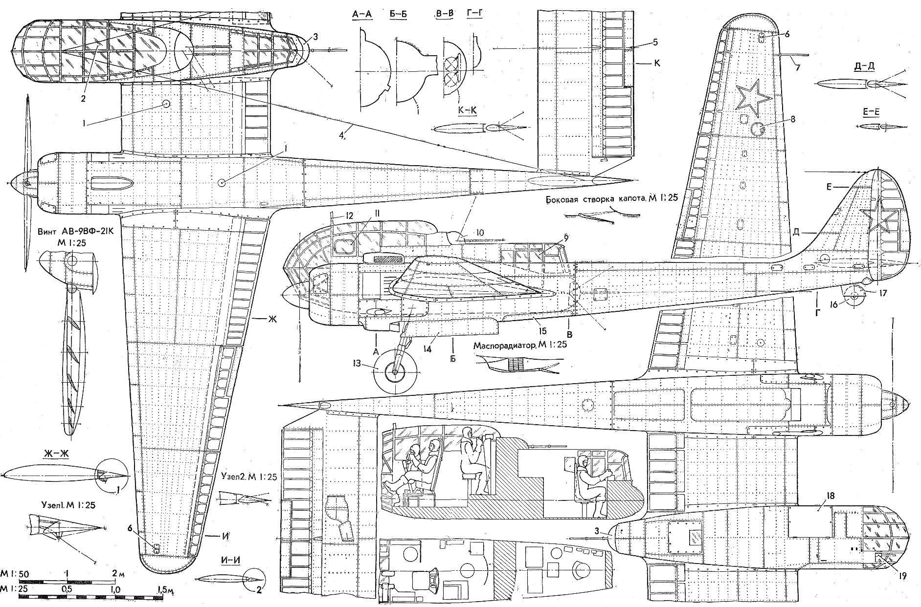
POWERPLANT originally consisted of two experimental engines AL-82M (power of 2100 HP each). In the process of factory tests these engines were replaced with serial air-cooled ASH-82FN designed by A. D. Shvetsov (1850 HP). The variable-pitch propellers AV-9ЕФ-21K vane Ø 3.6 m
The ENGINE cowling ring, rezhimno-drop-down, frontal, side blinds and shutters for regulating the temperature of the cylinder heads. For removal in the lateral gap of air that cools the cylinders, there was an additional “internal” hood. Its upper part is formed a removable panel suction pipe, lower — executed in the form of a cover, hinged and opening, along with fixed on it a cooler, damper and air tunnel. When the engine is on the ground and during takeoff the suction nozzle was closed by a special valve (dust filter), which elektromekhanicheski was associated with landing gear retraction system. After harvesting the flap is opened. The fuel system consisted of two wing tanks (with a capacity of 440 l) and two mitohondriej (capacity 180 l) tanks.
The aircraft was three infantry position: front fixed cannon (ammunition 100 rounds), the top firing point consisting of a sighting station and two guns (ammunition 200 rounds), and a rear firing position, with hydraulic control one gun. All guns of calibre of 20 mm.
SCOUT-SPOTTER su-12:
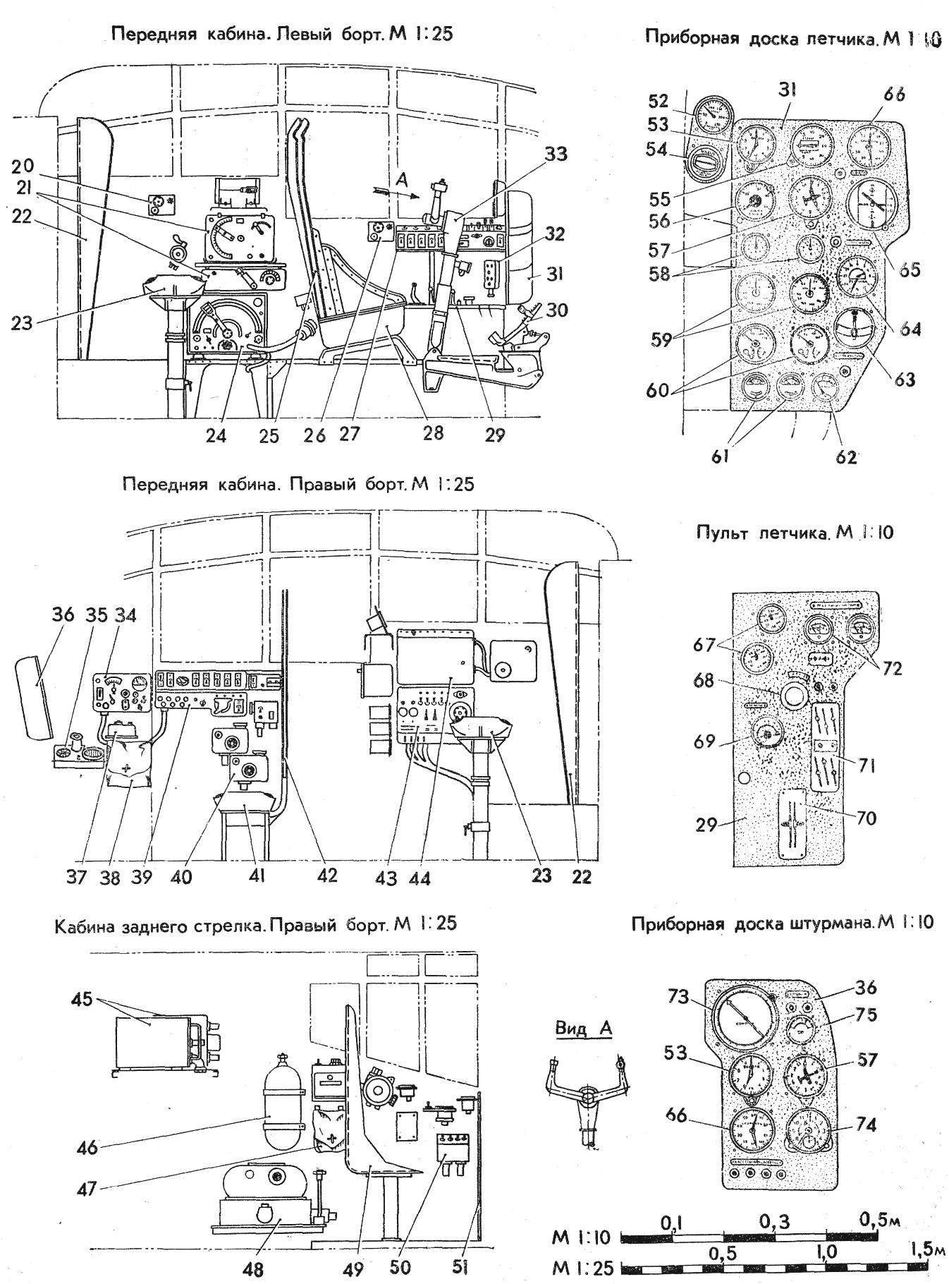
1 — filler neck ventsistemy, 2 — emergency escape hatch, 3 rear fire point, 4 — antenna, 5 — tail aeronautical fire, 6 — navigational lights, 7 — Pitot tube, 8 — Fara aircraft, 9 — door, rear of cabin, 10 — top firing point, 11 — window of the pilot, 12 — strut of the antenna mount, 13 — main wheel 900X300, 14 — doors of the main landing gear, 15 — sash bombolyuka, 16 — tail wheel 420X185, 17 — fold spike wheels, 18 — hatch front cabin, 19 — front small installation, 20 — phone shooter, 21 — radio 22 — armored plate of the shooter, 23 — seat arrow 24 to the transmitter 25 — pilot seat back armor (with shield), 26 — phone pilot, 27 — the electrical control of the pilot, 28 — seat pilot, 29 — remote pilot, 30 pedals, 31 — instrument panel pilot, 32 — bar electric alarm gear, 33 — rudder pilot 34 — control panel with radio, 35 — side reticle, 36 — dashboard Navigator, 37 — phone shield Navigator, 38 — satchel for cards, 39 — Energoatom Navigator, 40 — command devices of aerial cameras, the 41 — seat Navigator, a 42 — armored plate seat of the Navigator (screen) 43 — upper dashboard fire point 44 — Central distribution switch Board, 45 receivers of radio stations, a 46 — oxygen tank, 47 — satchel, a 48 — aerial camera, 49 — armored seat rear gunner 50 — control panel rear fire point, 51 — armored plate rear gunner, 52 — oxygen pressure gauge, 53 — altimeter two-point, 54 — indicator of oxygen, a 55 — variometer, 56, a radar altimeter, 57 — a pointer to the potentiometric remote compass, 58 — tachometers electrical, 59 — pointers of boost, a 60 — electric trehstranichnye indicators, 61 — the index of temperature of cylinder 62 is a pointer of the deflection angle of the flaps, 63 — electric turn signal indicator, 64 — remote magnetic compass with two indicators, 65 in the artificial horizon, the 66 — speed indicator, 67, compound 68 — a emergency valve the landing gear, 69 — index of benzenamine, 70 — sector normal gas, 71 — panel controls motors, 72 — thermocouple, 73 — a combined magnetic compass Navigator, 74 watch, 75 — ammeter.
The bombs were attached to the four two-way cassette holders on the sides of the bomb Bay, located in the tail boom over the chassis. It was eight bombs weighing up to 100 kg. Bombs can be reset one at a time or volleys of two. Sash Bay doors are opened hydraulically. To do this, each bomb Bay was mounted a single hydraulic actuator for both doors.
The aircraft had aircraft navigation equipment, radio communication equipment, electrical equipment, oxygen, photographic equipment, designed to perform aerial photography of the day and night.
The CREW consisted of four: pilot, Navigator, radio operator-gunner top gun emplacements and arrow back firing heat. To protect them was used bulletproof glass, steel plates and armor. The bottom front of the cab has been glazed 12 plates of glass, to protect the pilot and Navigator from the splinters of anti-aircraft missiles, spacecraft cabin floor under the pilot, Navigator and gunner were steel sheets and side — armor. Navigator defended flip (side) armor plate back of 8 mm thickness with 2 mm steel screen. Behind the seat pilot also had the armor back from two plates, and in front of the shooter-radio operator — wide armor plate 12 mm thick. the Rear gunner was protected from the fire of enemy aircraft two armored glass thickness of 90 mm armor plate. Against fragments of flak on the floor of the cabin were installed armor, and boards — armor plates, the Overall weight of the armor on the aircraft reached 450 kg.
THE COLOR OF THE PLANE. The surface, covered with canvas, painted with aluminum paint. The blades of the propeller and spinner in black. Tail rotor blades yellow. The dashboard and equipment enclosures dark grey.
In the process of thorough flight tests, in which participated such famous pilots as Stefanovski T., M. Gelpi, Anokhin S., Shiyanov and others, were made the following conclusions: “the Aircraft is stable and well obey the authorities, the climb is easy, browse the collection of great… allow the plane flying on one engine at all altitudes up to 6000 meters, and can fly with abandoned control. In performance the su-12 simple…” the Maximum duration of the flight at an altitude of 1000 m for more than four hours.
BRIEF TECHNICAL CHARACTERISTICS
Dimensions, m:
length……………………………………………………13,051
wingspan…………………………………………21,58
track width………………………………………..5,5
Area, m2:
wing……………………………………………………52,44
stabilizer……………………………………….10,5
The maximum flight speed, km/h:
earth………………………………………………….460
at the altitude of 5300 m…………………………………..531
The ceiling, m………………………..11000
The length of the run, m……………………………………220
Path length, m…………………………………..320
Flight range at an altitude of 1000 m, km….1140
Weight, kg:
empty………………………………………………….7552
takeoff……………………………………………….9510
N. GERDYUKOV, engineer
Recommend to read
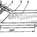 VERSATILE SLIPWAY
The wing of any aircraft should be smooth. It is clear. But how to achieve this? Each athlete solves the problem on its own. Beginner difficult — AA he has no more experience, eyes ve...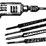 AFTER DRILL – needle files
Often, after the hole is drilled,further or a clean, slightly to expand or to make a slightly oval shape. This work can be facilitated steel Bender, automating it with a drill in a...
