
 We can safely say that the class of the ship ejection of seaplanes was the most short-lived in the history of Soviet aviation. There are many reasons, but chief among them is that in the heyday of ejection aviation fleet of the Soviet Union played a secondary role. In its structure there were only a few ships equipped with ejection systems.
From late 1938, this situation had to change. In the USSR adopted a program of construction of heavy warships, which were supposed to place 2 — 4 seaplane for reconnaissance, fire adjustment, and perform various support tasks. The launch aircraft was supposed to carry out with the help of catapults.
At the beginning of 1939 the people’s Commissariat of the Navy has developed a set of operational requirements for naval reconnaissance and announced a contest for its creation. It should be noted that the characteristics of the new aircraft was formed by the people’s Commissariat in accordance with the terms of its deployment and the start of ejection. The competition was attended by design teams with experience in the design of seaplanes, design Bureau, V. V. Nikitin, and V. B. Sharov, I. V. Chetverikova, and G. M. Beriev.
Nikitin in EDO not to develop a new aircraft, and put up for the contest slightly upgraded NV-4 created in 1936. Seaplane, submitted by aircraft Shavrov, was distinguished, as always, from the rest of the originality of technical solutions.
The aircraft OKB Chetverikova appeared to be the most superior flight characteristics. The vehicle was a flying boat, designed as a strut-braced high. As a power plant designer has chosen inline liquid-cooled engine M-103. Aircraft length was 9.5 m, height 4.25 m, a wingspan of 11.0 m. Flying boat had a top speed of 450 km/h, landing — 95 km/h and has a range of 1680 km. These data fully meet the requirements of sailors.
However, the people’s Commissariat of the Navy was made sufficiently illogical decision: the winner of the contest to announce project flying boat Beriev OKB, which was inferior to the aircraft Chetverikova on the basis of range, speed and overall dimensions.
Attempts to explain this decision by the fact that OKB Beriev had at that time considerable practical experience in the design of such aircraft, is not tenable. Previously created by Bergevin ejection scout KOR-1 was considered a failure and caused a lot of criticism from both flight crews and technical personnel.
Whatever it was, the decision of the Commissariat of aviation industry (NCAP) and Navy (NKVMF), adopted on 27 February 1939, passed a further design of the aircraft, the designation KOR-2, at the 31st plant in OKB G. M. Beriev. Today we can only speculate about what forces contributed to Believe in defending his project, but receipt of the order for the construction of the KOR-2 was saved by its dB from closing.
April 11, 1939, the design Bureau has presented a draft design of the KOR-2 to the command of the Navy, but he was rejected due to non-compliance with operational requirements for naval intelligence. In a Memorandum directed to 17 April 1939, the Deputy Commissar of the Navy N. Ignatyev in the MIND of the NC of the Navy, in particular, stated: “on 25 March 1939, comrade. Believe was directed at TTT KOR-2, which clearly indicated that the size of the aircraft both assembled and in folded position in any case should not be exceeded because of the dimensions of the hangar on the ship. However, in the present tov. By bergevin 11 April 1939 sketch of the project COR-2 TTT is not satisfied by the size, the flight data and a number of other requirements. To consider requirements not unrealistic, as the transmission Beriev design COR-2 the project was completed Chetverikova in compliance with all these requirements. In view of the above, presented the project meets as Management of aviation and Management of shipbuilding of the Navy of Kazakhstan. I ask for Your guidance comrade. Believe preliminary design of a boat version of the KOR-2 to develop again and in full compliance with the TTT Control of naval aviation”.
The full text of the memo noted the following deficiencies COR-2: exceeded the dimensions (1 — 2 m), small range (less than the required 400 km), low maximum speed (less than 50 km/h). Surprisingly, Believe and then managed to keep order and even to obtain the lifting sailors stringent requirements on the size of the aircraft. Most likely, the people’s Commissariat of the Navy considered it undignified to change the already adopted one decision. After all, what was the aircraft, was controlled personally by Stalin, and he does not forgive mistakes in decision-making.
An agreed technical specification for the ejection of the scout entered the plant on 31 July 1939. EDO aircraft assigned internal index of MS-9. After all the organizational problems were solved, the design Bureau team with great enthusiasm started creating new aircraft. About what is expected of them very good aircraft, chief designer constantly reminded all who took part in the design of the machine.
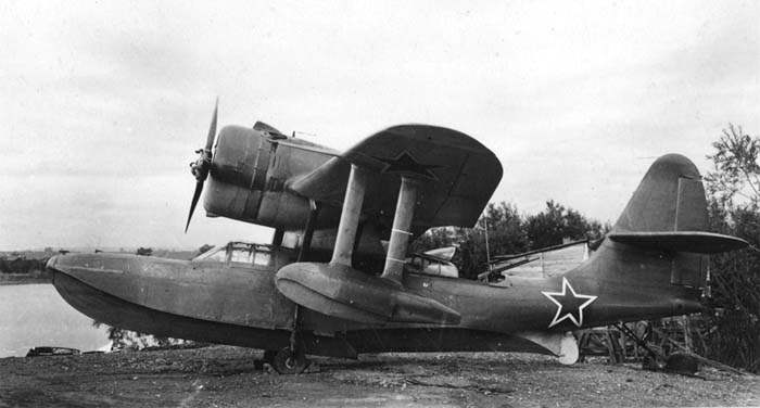
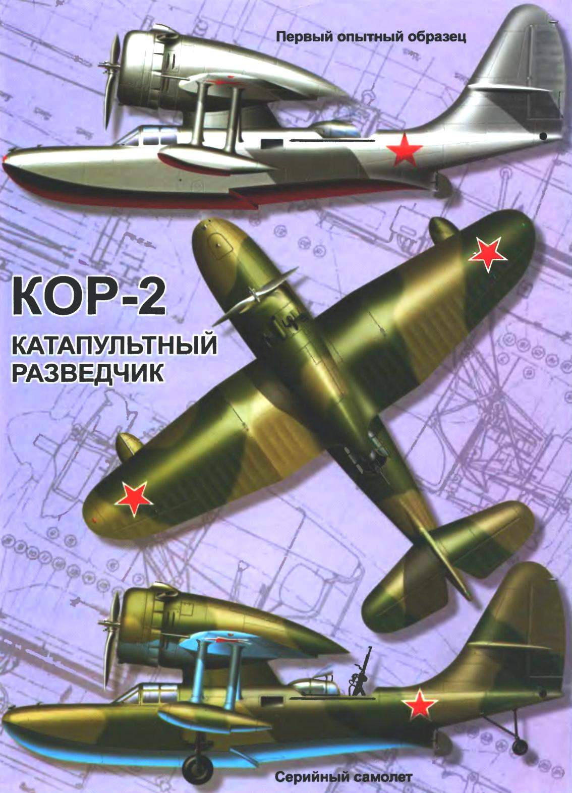
All work was carried out at an accelerated pace: from technical requirements to the construction of the aircraft took only 14 months. In October 1940 the first prototype of the KOR-2 (MS-9) was rolled out of the Assembly shop. October 2, 1940, the plane made the first taxiway on the sea of Azov, and on 21 October, test pilot plant N. And.Kotkov made its first flight. Was soon built and the second prototype.
Factory flight testing was completed in January 1941. After both instances of the KOR-2 was transferred to the state tests, which were held in Sevastopol on the basis of LEAH’s naval air force: the first flew marine pilot captain S. B. Reydel, the second captain P. Ya. The entire testing program were available for 16 days (from 2 to 18 February 1941) — this time it was done 42 flights with a total duration of 28 hours 13 minutes. Timeline of creation of the plane looks like this: 31.06.1939 year — results KB TTT plane; 7.04.1939 of the year — presentation of preliminary design; 21.04.1939 of the year — the presentation of the layout of a seaplane; 8.10.1940 — 27.01.1941 year factory testing; 2.02.1941 -18.02.1941 of the year state tests.
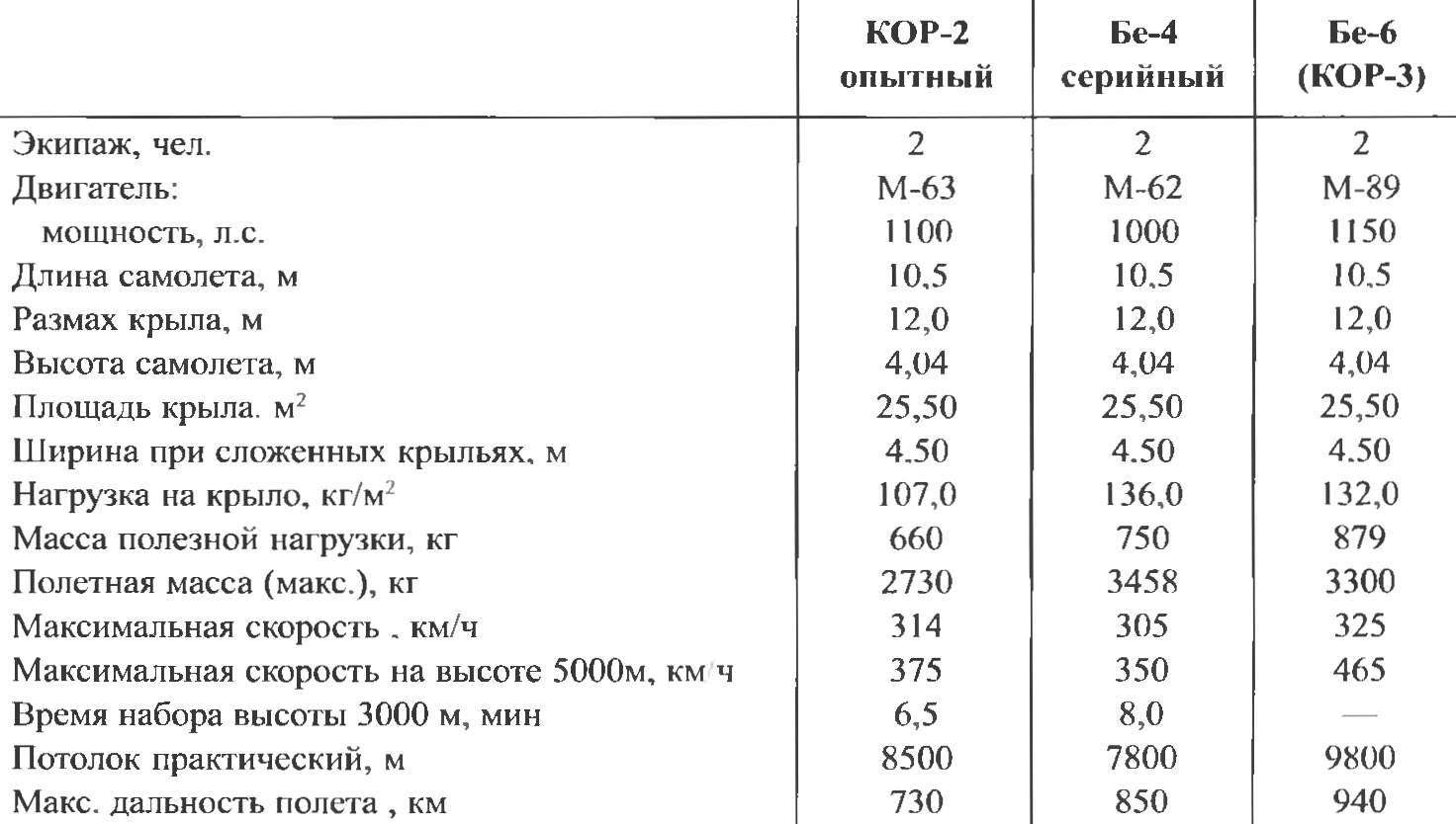
In the final act stated: “an Experienced seaplane COR-2M-63 design engineer comrade. G. M. Beriev, built in 1940, the plant number 31 NCAP, performance data corresponds to the decision of Committee of Defense in SNK from 04.03.1940 and satisfies tactical requirements of naval aviation. Seaplane COR-2 the state of the test stand and is recommended for aircraft weapons of the Navy of the USSR”. Noted the simplicity of the piloting of the aircraft and ease of use the possibility of using flying boats in addition to reconnaissance and adjustment of fire for the protection of water space. In this case, it is recommended to increase to 200 kg bomb load and range by installing in the fuselage for additional fuel tank.
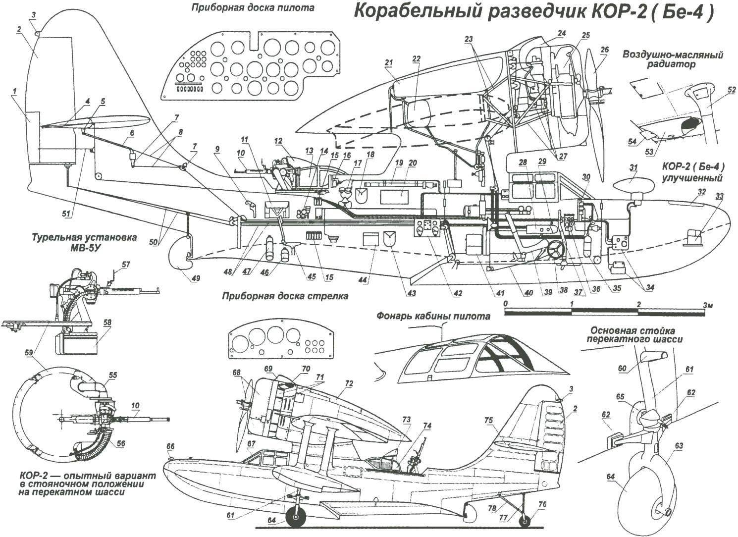
Ejection naval seaplane reconnaissance KOR-2 (be-4):
1 — the trimmer of the rudder; 2 — rudder; 3 — dimensional tail lamp; 4 — pull the trimmer of the Elevator; 5 — rocking of the Elevator; 6 — pull rudder; 7 — rocking channel Elevator control; 8 — thrust Elevator control; 9 — rocket launcher; 10 — gun ShKAS; 11 — portfolio storage Murmansky cards; 12 — flip visor canopy arrow; 13 — sliding canopy of the shooter, 14 — oxygen device KPA-3; 15 — ammunition pouches for flares, 16 — dashboard arrow Navigator; 17 — compass A-4; 18 — shoulder bag for microphone with the phone; 19 — optical bombsight (OPB-1M) in the stowed position; 20 — cabin Windows arrow; 21 — main fuel tank; 22 — additional (auxiliary) fuel tank; 23 — frame mount power fire frame; 24 — carburetor air intake; 25 — engine M-63; 26 — the variable-pitch propeller VISH-105-62; 27 — the engine mount; 28 — engine control unit; 29 — ORE; 30 — instrument Board; 31 — frame radiolucency in the fairing; 32 — bale nose compartment; 33 — battery; 34 — units radiolucency; 35 — oxygen tank; 36 —a fuse box; 37 — control knob; 38 — control wheel trimmers; 39 — the pilot seat; 40 — the control cable of the Elevator trim tabs; 41 — a-bag with emergency supplies of food and drinking water; 42 — technodelic; 43 — a-bag for portable lamp; 44 — box of six aeronautical bombs; The 45 — seat Navigator 46 — parachute flare; 47 — oxygen tank; 48 — rope control wiring; 49 — water rudder; 50 — traction-control rudder; 51 — control rod trimmer rudder; 52 — fairing mount wing brace; 53 — fairing air-oil cooler; 54— adjusting valve; 55 — pipe hillsoboro; 56 — link safety belts; 57 — scope; 58 — ammunition box; 59 — ring of turrets; 60 — footrest; 61 — stand erratic chassis; 62 — support feet of the rack; 63 — fork-wheel; 64 — wheel main landing; 65 — axis mounting rack; 66 — mooring unit; 67 — canopy canopy; 68 — removable panel of the engine hood; a 69 — fairing air intake 70 — exhaust pipe; 71 — fold cooling jacket of the engine; 72 — detachable panel; 73 — canopy canopy arrow in the open position; 74 — canopy arrow in open’ position; 75 — stabilizer; 76 — erratic tail wheel supports chassis; 77 — tail stand erratic chassis; 78 — strut tail strut erratic chassis; 79 stand — up wing float; 80 port bow machinegun; 81 — fixing unit of the main stand erratic chassis; 82 — wing floats; 83 — redan; 84 — the attachment points of the tail strut erratic chassis; 85 — a of the wing struts; 86 cover hub mounting bomb racks; 87 — wing of ANO; 88 — Aileron; 89 — external landing flap; 90 — Central landing flap; 91 Luc install bomb sight; 92 — Luke the installation of the camera AFA-27T; 93 — the steering wheel height; 94 — trimmer rudder; 95 pen; 96 — air-oil radiator; 97 — suspension bombs FAB 100
As the shortcomings in the act was noted by an unstable supply of ammunition for machine guns ShKAS, the vibration of the sight PBP-1 and OPB-1M and bad glazing turret installation. Customer required to rectify the defects, all the non-serial units serial to replace, as well as to provide for the installation ground the chassis and equip the boat with radiolocator RPK-2
With the outbreak of war the work by COR-2 to have increased From 23 July to 5 August in the Bay near Oranienbaum spent the last phase of testing perform 12 starts using the new ejection setup that is created on the Leningrad PTO plant named after S. M. Kirov. After this COR-2, under the designation of the be-4 was adopted by ships of the Soviet Navy.
Serial production of the new seaplane was deployed on the basis of the final aircraft factory No. 288, located North of Moscow. It was planned that the first series will be
20 machines Serial firstborn, the construction of which was completed on 11 August 1941, unlucky: 9 September, the car crashed, killing part of the crew of a military technician 1st rank Sukachev.
Second serial the seaplane took to the air on September 20. After Assembly of the third instance of the factory was evacuated to Omsk there at the aircraft factory No. 166 continued a series of be-4. By the end of 1942, managed to collect 9 seaplanes.
In may 1943, OKB Beriev had to move again to a new location, now in Krasnoyarsk. But even in the course of incessant moving from place to place, the design Bureau continued to work on improving the flying boat and to address these in the act of acceptance of shortcomings. So, on some aircraft, instead of ShKAS machine guns began to install a large-caliber 12.7 mm machine gun type BC design by M. E. Berezin. And increased defensive armament, setting the turret VUB-3 heavy machine gun UBT.
Successfully tested missiles and weapons. After modifications, the aircraft could carry under each wing, two or four RS-82 rockets. Each wing has added one more beam to the holder, which Be-4 could carry four FAB-100 or PLAB-100 Inside the fuselage began to install two-piece fuel tank, total capacity 300 liters. Just built a 44 aircraft of the be-4, of which in service until the end of the war there were about 20 copies.
The story of the creation of the be-4 will be incomplete if not to mention that in OKB G. M. Beriev in 1940 — 1941, in accordance with the decision of Committee of Defense in SNK, were the development of ejection of the scout KOR-3. As the base of the machine when creating the KOR-3 planned COR-2. The main difference between the KOR-3 was supposed to be the power plant, which included a new engine М64Р; this slightly changed the shape of the hood was Studied for several variants of the aircraft: boat, floatplane and aircraft with wheel chassis with the ability to use it with a base and airfields.
21 APR 1941 Beriev submitted to the Office of aviation Fleet project of KOR-3 in all three single-engine flying-boat with strut-braced high-set wing and engine M-89; single-engine flying boat with a high cantilever wing, based on the pylon of the boat and flying boat with a high wing and engine M-107 installed inside the fuselage. The case for the establishment of KOR-3 was limited to a discussion of the project, but subsequently, some technical solutions have been applied in recent ejection scout KL-145, developed in OKB.
Information about using the float plane Be-4 during the war period remained a bit. To the complete liberation of Soviet territory from German troops flying boat be-4 for its intended purpose fleets were not used. They are based on the Bank and perform auxiliary and patrol tasks In the field trips of factory experts, having in part to provide technical support warranty machines can be judged on the areas where I flew these planes. These include Poti, Tuapse, Sevastopol, Leningrad, Murmansk and Vladivostok.
In the second half of August 1942 the first 4 cars arrived at the black sea fleet, forming a single adjustment link. The division was based in the area of Tuapse. By mid-September the crews had mastered the new aircraft and began the task of protection of coastal areas, finding enemy submarines and exploration of water areas In early October, the link included in the 60-th separate squadron, based in Poti. In the course of performing a patrol flight crews KOR-2 happened to meet with German seaplanes, but every time it ended for both sides to no avail.
In early 1944, the time of recovery on the ships catapults remained in service only 3 of the 7 set out in the ship units of the aircraft. July 1, 1944, they joined the 24-th separate squadron of the black sea naval aviation, which was the basis of coastal scouts Be-4. In 1945, in the composition of this part was still 8 Be-4, which continued to be used until full development of the resource.
In 1944, the first Be-4 appeared in the Baltic sea in the part of the 29th separate reconnaissance squadron. The main objectives of these was the rescue of downed crews and an emergency landing of the aircraft; less often they flew on reconnaissance and patrol of coastal areas. Only the Baltic sea have been 12 boats Be-4. On may 9, 1945 remained in service nine of these machines.
The Pacific ocean the first two aircraft be-4 arrived in mid-1942. Just before the war with Japan in the Pacific fleet were four of the ship’s scout Planes were part of the 115th regiment of fellow scouts Pacific fleet had on his armament of the cruiser “Kaganovich” and “Kalinin”, with catapults which flew Be-4. In the period of military actions of the USSR against Japan, the aircraft carried a patrol, in search of enemy submarines.
Design a flying boat KOR-2
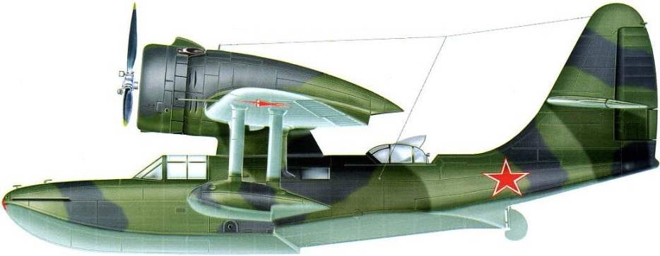
Seaplane KOR-2 — ejection all-metal reconnaissance, spotter and the middle bomber, designed according to the monoplane scheme with high-wing strut-braced and cantilever wings. The crew — two people: pilot and Navigator-shooter. The fuselage is made in the form dvuhrjadnoj the boat redan had in plan wedge shape: the second was curved, it installed a water rudder, operated from the pedals.
Power set of the fuselage of the extruded sections; the main material is made of anodized aluminum Cross set of the 25 frames; №№ 10, 12,15, 18,19, 23, 25 — reinforced, No. 5, 10,15 — in the form of watertight bulkheads. Longitudinal set consisted of keel beams and stringers. The fuselage is of duralumin plates with a thickness of 0.8 mm. Riveting done wpoty.
Functionally, the boat is divided into four compartments. The bow section is sealed, it occupies the space to frame No. 5. It established the battery and store baltinstrument. If necessary, this compartment was used as a cargo. Access is through a hatch with an airtight lid.
Between the frames No. 5 and No. 10 was a closed cockpit glazing of Plexiglas. The entrance is through folding on both sides of the cover. The pilot seat shifted to the left of the plane of symmetry, allowing, if necessary, install a removable dual control, used for initial training and workouts. In the cockpit housed a full set of instrumentation, provide flight in adverse weather conditions and at night.
On the front of the dashboard housed the airspeed indicator, altimeter, variometer, gyromagnetic compass MMC-2, turn indicator, artificial horizon, clock, AVR, magnetic compass KI-10, toggle switch switch, pressure-vacuum gauge, tehstroy indicator oil temperature, oil pressure and pressure of gasoline. On the right side of the dashboard mounted fuse box alarm operating during ejection from the ship. On the left side of the cabin were lever engine control, oxygen device KPA-3, 2-liter oxygen cylinder, the device is an aircraft intercom (SPU-2) and the switchboard. Of accessories in the cab had a bag with intercom system, bag for portable lamp, first aid kit, a pocket for correction of tables of aerodynamic devices, a cat and a floating anchor.
Catapult seaplane-scout KOR-2 (be-4)
In the 10th frame was built watertight door connecting the cockpit and Navigator. The space Navigator with installed turret machine gun to protect the rear hemisphere was located behind the pylon. To protect the shooter during firing machine gun mount were closed by a movable screen. The co-driver seat under the turret for swinging the bracket could adjust the height. In front of the seat in the floor and the bottom of the boat there was a hatch over which is mounted the heel to fasten a bombing sight OPB-1M.
Before the turret was the dashboard Navigator, which are placed on the altimeter, speed indicator, clock, multi-meter. On the right side of the cockpit of the Navigator was assigned to the Central switchboard, the radio station RSRM-3, electrovaporization, camera AFA-27T and first aid kit. On the left side of the cabin were brackets in the stowed position of the sight OPB-1M, sextant, compass A-4, SPU-2, oxygen device KPA-3, bag with intercom system, bag for portable lamps, signal flares, a flare gun (flare gun), a bag with navigational facilities, air navigation drawer for six bombs and two rocket parachute PAR-13.
In the free space between 10 and 12 frame kept the bag with an emergency supply of food, a container of drinking water pump for pumping water, hand pump, signal flags and a container of spare parts to the station. In the rear compartment of the boat installed the fin and stabilizer control surfaces.
The basis of the power plant of the aircraft was the engine M-63 (or M-62), was connected via rubber shock absorbers. It also included fuel, oil and fire system. The engine M-63 air — cooling single-row radial arrangement of cylinders, direct drive screw, and a two-speed supercharger. Power M-63 on takeoff— 1100 HP
On the machines of the first series of engines were equipped with three-bladed metal propellers variable-pitch AV-2-4, later — the screws VISH 105-62.
Engine mount truss, welded from hromansilevyh tubes followed by heat treatment. Hood type PASS is fully closed the engine. Cooling air was regulated by a cooling jacket. The fuel system included two tested fuel tank, shutoff valve, filter, manual fuel pump and pipelines. Main fuel tank capacity of 410 litres and secondary capacity of 120 liters was installed in the fairing of the engine. Tanks are welded of aluminum alloy AMC, and for the rigidity they had internal power set of profiles and partitions.
The oil system consisted of a tank, radiator, drain cock and pipe. Tank capacity of 56 litres, brewed from AMC, has been mounted on Motorama behind the firewall.
Fire safety system, in addition to the fire extinguisher at the fire wall, had the wiring to the fire assemblies — the engine, the carburetor, benzarone. For giving effect to turn the valve on the cylinder with carbon dioxide, located on the left side in the cockpit.
Wing — scheme “reverse gull”, two-spar, with working trim, consisted of a center section and two consoles, which for easy storage on the deck of the ship was performed foldable. The installation angle of the wing 5 degrees. Console had a transverse V at the toe of the wing is 4 degrees, and center — back cross V equal to 7°13″.
A wing fixed to the pylon, which is structurally made integral with the boat.
The profile of the wing PAZ-22. The relative thickness at the root of the wing 13.85 percent and at the ends is 9 percent. To improve the landing characteristics of the wing of the aircraft were fitted with flaps of the type shrank, consisting of five sections — three were located in the center section and one for consoles. The plane’s ailerons had axial compensation. The frame of the Aileron consisted of a spar and rib truss type.
The shanks of the wing center section, ailerons, and tail rudders were covered with fabric, the rest of the wing had a duralumin casing with a thickness of 0.8 to 1 mm. the front of the Aileron to the spar was made of sheet aluminum with a thickness of 0.8 mm, and the back of the canvas.
To ensure lateral stability of the aircraft afloat on consoles of the wing mounted underwing odnorodnye floats, mounted on two streamlined struts. Floats the standard design, their frames made of a set of extruded aluminum profiles and sheet duralumin covering. To lift the flying boats on Board the ship in the center section had four eye. Slings for lifting was made from steel cable and placed in the free volume of the nacelle.
Empennage cantilever, the standard scheme. The keel was performed as a single unit with the rear part of the fuselage. The stabilizer was firmly fixed on the fin. The installation angle of the stabilizer +3°30″. The stabilizer and fin have the same design and consisted of two spars, a set of ribs and stringers. The covering of the tail—dural.
Rib — truss; socks them stamped from sheet material. Socks rudders were trimmed with sheet aluminum, back — cloth. The handlebars had axial aerodynamic compensation. To reduce the effort on the pedals and stick control of the rudder and elevators were supplied with trimmers. Ruled trimmers with the help of the knob installed in the cockpit.
The aircraft control system mixed the ailerons and Elevator it was done with a pen and a tubular duralumin rods, and control the rudder — pedals and cables, which had adjustable stops to limit the stroke. Flaps retracted and released the controls mounted on horizontal pipe the pilot seat on the right side.
Motor control — from ORE that is installed on the left side of the cockpit. Water rudder is controlled by pedals.
Erratic chassis, used to move aircraft on deck or shore airfield consisted of a truck main gear and tail trolley. Chassis single welded structure, mounting was carried out to the front node of the strut of the wing on the boat and ejection to the axle with pins. Wheel type balloon, size 470×210 mm.
The tail trolley of welded construction. Mount to the boat was carried out at three points with pins. The tail wheel truck — type balloon, size 300×125 mm. the Changing direction of the chassis by using the handle mounted on the rear truck.
The radio equipment consisted of a radio RRM-3 and radiolucency RPK-2. The radio station was located in the cockpit of the Navigator. Receiver and RUNES RPK-2 was installed in the forward sections of the boat. Managing radiolocator implemented in Navigator’s cockpit. Internal communication between the pilot and the Navigator were maintained with the aircraft intercom SPU-2. The main source of electricity was on Board generator type GS-1000. The aircraft had a camera AFA-27T, which in the stowed position was located behind the seat of the Navigator.
The seaplane was equipped with a small and bomber weapons. Shooting consisted of two 7.62 mm ShKAS machine guns. Fixed a machine gun course was right on the flight in the bow of the boat, with ammunition — 500 rounds. The fire from it was led by the pilot, using sight PBP-1 on the dashboard in front of the windshield.
Flight characteristics of aircraft of COR-2
Turret MV-5U with a machine gun ShKAS ammunition 500 rounds was located in the middle of the boat over the cockpit of the Navigator. To monitor the results of fire and performance of training of firing on the plane could be chinafotopress PAH-22.
Bombs weighing up to 200 kg is suspended by means of locks D2-M two beam holders mounted at the junction of the center section and outer wing panels. Dropping bombs was operated by the Navigator using electrospecter ASBP-3P or pilot — with the help of emergency derailer. Aiming was done using optical bombsight OBP-1M. There are the following suspension options: two FAB-100, or two FAB-50, or four sub-25.
In the process of mass production of the weapons has changed. The bomb load was brought up to 400 kg, which has mounted two additional bomb racks. Provided for the use of four rockets RS-82. Turret MV-5U replaced by VUB-3 and mounted a heavy machine gun UBT.
N. Food reserve was, A. CHECHIN
Recommend to read
 TIME TO REFURBISH THE WINDOWS
In a city apartment, a dacha and in a garden house wooden window frames periodically require ponovleniya & painting, glass — coating or replacement if cracked or broken. All of this... AND SAW, AND “OPENER”
Some time ago folding blades supplied by industry mainly for the army. Now widely available and are popular with motorists and hunters, geologists and fishermen, campers and even...
