The helicopter was fitted with the same engine and navigation instruments like the Ka-10. It was supposed to install the rsiu-4M battery powered, provides a range of two-way communication up to 50 km when flying at an altitude of 1000 m. the transmitter and Receiver were placed in the area of the dashboard. The helicopter was provided for the placement of the flare gun with a supply of missiles.
Chassis CA-17 provided a simplified depreciation system with simple leaf springs, as the experience of operating the Ka-10 showed that the estimated vertical speed at landing was greatly overestimated, and in practice, the helicopter dropped at a speed of about 0.5 m/s In one of the documents States: “the Presence of attenuation, absorbing the entire standardized work, it is useless and only stageset design. Many foreign light helicopters have long operated without depreciation”. The helicopter’s skid and ski type, made of duralumin tubes. The curved tip was made of steel. For transporting skis mounted flap wheels. If necessary, the marine variant, the skis can be replaced dural cradles for baronetage (inflatable float) chassis type: Ka-10.
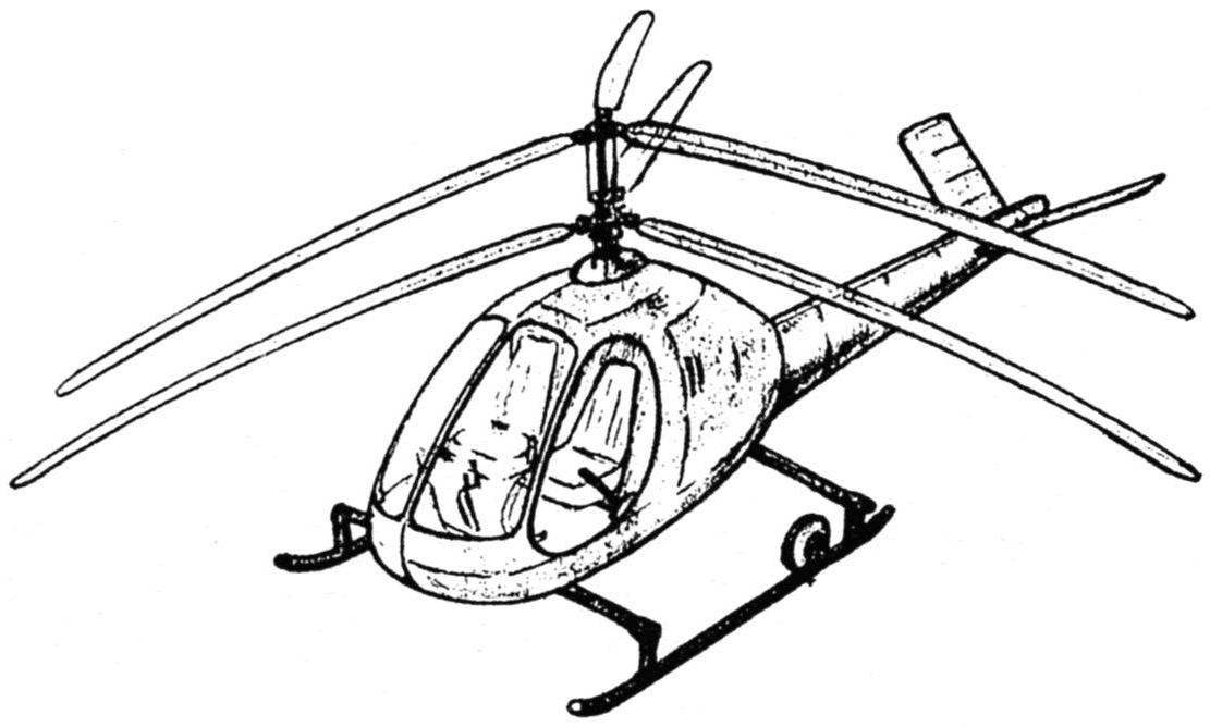
Ka-17 to land (ski) chassis
Ka-17 on a sea (float) chassis
Diagram of the collective pitch control, with gas and stabilizer
The may 21, 1953 N. And. Kamov has produced a “Considerations about the project Ka-17”, which was supposed to attract potential buyers and provide funding for technical project and manufacturing of the prototype. According to Kamov, the new helicopter could be used as a coherent military, training in the system of DOSAAF, in the frontier of aviation “to carry the guard service at the border posts and border posts, especially in areas with rough terrain”, patrolling high-voltage lines or pipelines, the exact location of shoals of fish with Seiners, the meteorological sounding of the atmosphere, air ambulance for emergency medical care in remote areas, to postal communication and solving some other problems.
Nikolai Lenin believed that the simplicity and adaptability will make possible the mass production of the Ka-17. It was divided into separate units that were supposed to go on the conveyor “is as full internal detail.” Was supposed to completely eliminate individual adjustment of the individual items on the conveyor, preventing a uniform release of cars.
“Considerations about the project Ka-17” was sent to potential customers, however, the design office has not received the necessary funding through direct contracts. In the public order and the approved plan of the Ministry the means to it are also not provided, therefore, the Ka-17 was suspended at the design stage, the main efforts of the OKB directed on creation of the helicopter Ka-15.
Flight characteristics of the Ka-17
Flight weight, kg 500+2%
Payload, kg 231,5
Crew. 2
Static ceiling, m 1000
Dynamic ceiling, m 3500
The maximum speed, km/h 120
Flight time, h 2,5
Range, km 200
The diameter of the plane of Oltenia screws, m 7,0
The number of revolutions of the rotor per minute 380
The profile of the blade root PASS-23014
The profile of the blade end of the PASS-23009
The fill factor 0,0376
The number of screws 2
The number of blades of each screw 3
The length of the helicopter without the blades, m 4,5
The width of the helicopter without the blades, m is 1.6
The height of the helicopter, m 2,56
Recommend to read
 FIRST GIMLET
To facilitate the screwing of the screws in the wooden part or wall of the tube made a simple device — a small gimlet, and doing some preliminary socket-deepening. Here is it the screw... EXPLOSION-SCISSORS
How soft and manageable fire "snakes" rolled in the hands of the rollers, they are so stubborn and hard to handle in the cold when cutting them on the measuring of the workpiece. Cutting...

 Operation of the first single-seat Ka-8 and Ka-10, created in OKB N. And. Kamov, showed obvious advantages of coaxial-rotor. Along with the compact that was excellent handling and maneuverability, the ability to make takeoffs and landings in difficult conditions, which has opened up opportunities for the use of helicopters of this type.