
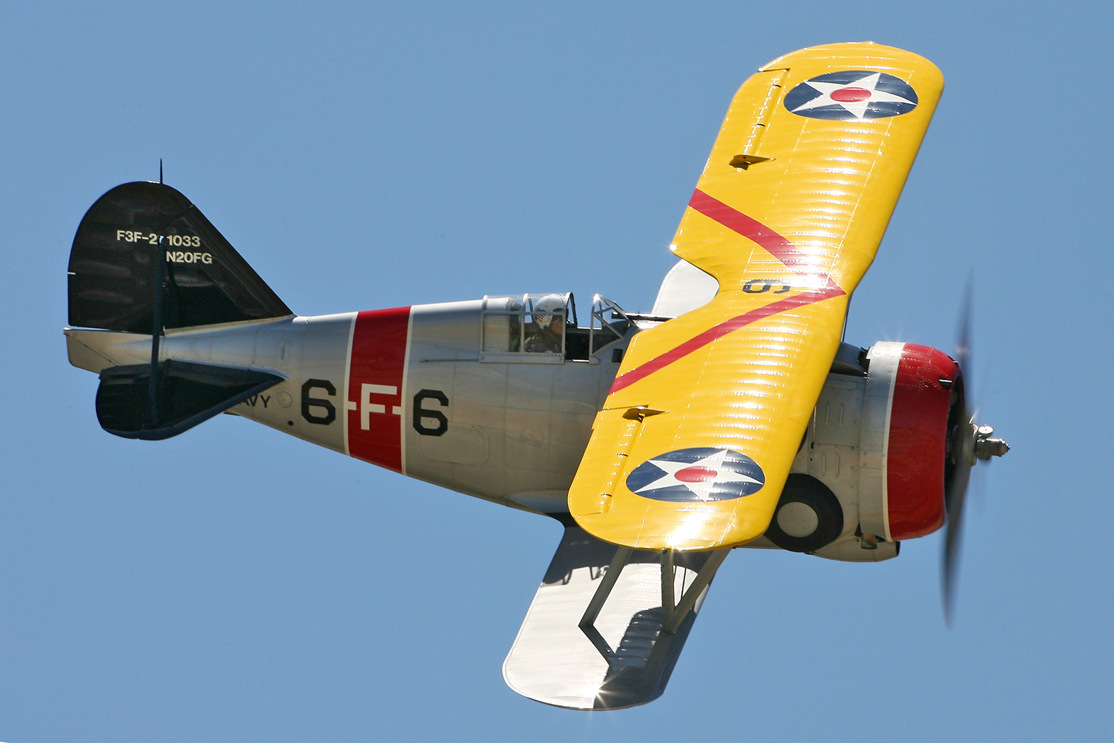
 Carrier-based fighter Grumman F3F of the company. In the early 30-ies of the American company Grumman was the undisputed leader in the production of fighter biplanes for carrier-based aircraft. The reason for this was the desire of the designers of this company to apply on their aircrafts with the latest technical achievements. The firm’s assets — development of the original scheme of the landing gear, enclosed cockpit and all-metal fuselage-monocoque with a smooth lining.
In October 1934 the firm Grumman began designing the aircraft, which organically focused all these design innovations. This machine became the latest in a family of carrier-based fighter biplane aircraft F3F.
Development F3F wearing at the design stage brand designation G-11, began on 15 October 1934. This date coincided with the beginning of serial deliveries of the previous model of the company, Grumman — fighter, the F2F-1. The initiator of the new machines was the company itself. In an effort to focus the attention of officials of the military authorities on the lack of stability and poor landing characteristics F2F, she tried to make a new car more perfect.
Representatives of the Navy gave the plane the designation for F3F-1. When a large resemblance with the new F2F fighter had significant differences. The fuselage of the F3F-1 was extended by 533 mm, 1120 mm increased wing span. The diameter of the wheels of the main chassis has been reduced — this would make the plane less “paunchy”.
Starting the dive from a height of 2438 m, Collins in the output generated 9-times the overload, and the design of the fighter could not resist: the aircraft came off the engine and wings. The fuselage fell four kilometers to the East of the Grumman plant in Farmingdale. Eyewitnesses of the fall tried to pull the body of the pilot from the crumpled fuselage, but there was a fire…
Testing continued on the second prototype, which was given the same serial number. The design of the machine has been strengthened. The first flight took place on 9 may 1935. Four days later the car was transferred to the air base Anacosta for flying by military pilots. May 17 pilot Lee Gelbach fell into a tailspin; in an unsuccessful attempt to bring the aircraft out of a death spiral, he made 52 of the coil and at a height of 610 m jumped with a parachute. The plane continued to stopwrite to the ground.
After this incident, the designers of the firm Grumman obsessed with the refinement of a fighter. The third prototype, the increased area rudder and found two more small rudder under the aft fuselage, in the area of brake hook. At the request of the military, airline put a more powerful engine R1535-84 and the new air screw. Powerplant was 20 kg lighter than the old, and to preserve the alignment had to the front of the crankcase to attach a cargo — steel pipe filled with bolts.
These improvements have delayed flight testing until July 10, 1935, although in the construction of the third aircraft was used some parts from the second. The firm was in a hurry for good reason: the Navy urgently needed a new fighter. In operation recently joined the aircraft carrier “Ranger”, were laid two heavy-type aircraft carrier “Yorktown”, so that the overall needs of the Navy in the fighter was estimated at 150-200 aircraft.
24 Aug 1935, the US Navy ordered 54 of the firm Grumman fighter F3F-1. Finalized testing of the third prototype XF3F-1 was successfully completed in March 1936. Delivery of production aircraft F3F-1 lasted from January to September, 1936. On serial fighters instead of right 7.62-mm machine gun mounted 12.7-mm machine gun. Such weapons would become the standard for all subsequent modifications. Like all other fighters of the firm Grumman, F3F-1 had adjustable horizontal stabilizer with a working range of angles from +3,75° to -2,50°.
The first division, received a new fighter, the squadron became VF-5B. “Ranger”. During their operation there have been several accidents when the training dogfights the pilots to pilot the F3F-1, all of a sudden lost control. The investigation of air accidents showed that the cause of this was the destruction of the attachment of the upper wing or the Aileron hardpoints. The firm has gone on the introduction of restrictions on maximum overload of up to six times.
July 1, 1937, began the reorganization of marine aviation, the squadron received a new number and color scheme coloring.
After adopting a fighter-monoplane F2A-1 Brewster company the biplane GRUMMAN F3F-1 were led to training units and flying schools.
Work on a new fighter monoplane F4F-1 firm Gmmman was slow. The developers had big problems with the power plant, and in the interim, the management company has offered the military to modify F3F, setting him on 865 HP engine WRIGHT R1820-G5 CYCLONE. With a motor of such power characteristics of a fighter-biplane did not differ from the respective characteristics of the fighter-monoplane. According to the calculations of designers, the biplane could have a top speed of 411 km/h, and installing turbocharger allowed to bring the ceiling plane to 9205 meters.
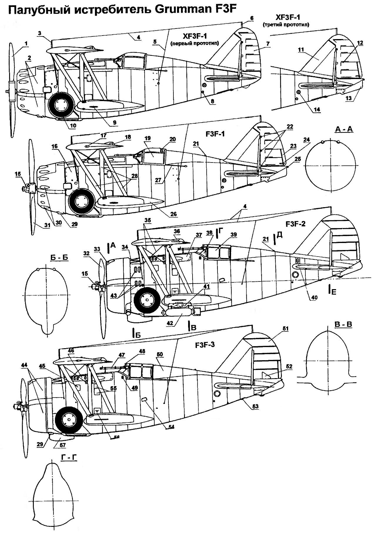
Carrier-based fighter Grumman F3F:
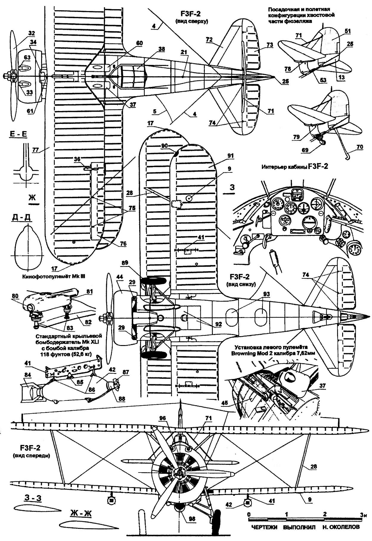
1 —two-blade metal propeller with a constant pitch Lycoming company; 2 — removable hood panel engine Pratt & Whitney R-1535-72; 3 — the wing mast antenna radio; 4 — cable the radio antenna; 5 — cable of the radio station; 6 — tail antenna of the radio station; 7 — rudder; 8 — lifting pipe; 9 — landing light (only on left wing); 10— wheel main landing gear in the retracted position; 11 Kil; 12 — rudder (larger); 13— fairing hinge brake hook; 14— cover flap control rods control; 15 — the mechanism of changing the pitch of the screw; 16 — a removable access panel in the compartment units; 17 — left ANO; 18 — rocking Aileron; 19 — sliding part of the cockpit canopy; 20 — enhancing the binding of the cockpit; 21 — flashing beacon; 22 — the hinge of the rudder; 23 trimmer of the rudder; 24—thrust of the trimmer of the rudder; 25 — marker light; 26 — fairing lower wing; 27 — guides for the sliding rollers of the flashlight; 28 — N-shaped wing strut; 29— tube exhaust manifold; 30 —fairings of the cylinder heads; 31 — two-blade metal variable-pitch propeller Hamilton Standard; 32 — three-blade metal variable-pitch propeller Hamilton Standard diameter of 2740 mm; 33—safety extension tube 7.62-mm machine gun Browning Mod 2; 34 — the air intake duct of the carburetor; 35 — brace struts of the upper wing; 36 — fairing thrust Aileron; 37 — access cover Browning machine gun Mod 2 7.62 mm; 38 — visor of the cockpit; 39 — reinforced modified sliding of the lamp; 40—air intake; 41 — wing bomb rack Mk XL1; 42—explosive bomb MK IV caliber of 52.7 kg (116 lb); 43— crack release of the cooling air; 44 — hoods of the type NACA; 45 — Luke filler main fuel tank with a capacity of 314 litres; 46 — cover access to the extension tube of the gun; 47 — telescopic sight Mk III Mod 4; 48 —review mirror rear hemisphere; 49— handrail; 50 — cover of the liferaft; 51 modified rudder; 52 — the hatch of the access control mechanism of the trimmer of the rudder; 53 — the tail wheel in the retracted position; 54 — step; 55 — Luke ammunition 7.62-mm machine gun Browning Mod 2; 56 — Luc fuel filler auxiliary fuel tank with a capacity of 178 l; 57 —housing oil cooler; 58 — the movable part of the lamp in open position; 59 — headrest; 60— cap access to a 12.7-mm machine gun Browning Mod 2; 61— cap filler oil tank; 62 — brace the upper wing; 63 — a safety extension tube of 12.7-mm machine gun Browning Mod 2; 64 — Dragoon of the main stand; 65 — strut main landing gear; 66— fold hatch of a storage box of 12.7-mm machine gun Browning Mod 2; 67 maintenance hatch to access the fire extinguisher; 68 — an access hatch in the radio compartment; 69 —the tail wheel is in the released position; 70 —a boarding hook in the released position; 71 — brace stabilizer; 72 — stabilizer; 73 — the steering wheel height; 74 — hinge rudder; 75 — hinge ailerons; 76 — Aileron; 77 — the left side console upper wing; 78 — drive sock stabilizer; 79 — fire threat convergence; 80 lens camera; 81 — the camera body; and 82 — the upper center section of the wing; 83 — attachment points of the camera; 84 — stabilizer; 85 — mounting; 86 — emphasis; 87 — pox arming of the Fuze; 88 — fuse; 89 — wheel main landing gear in the released position; 90 — drill fire; 91 — the left side console lower wing; 92 — fold hatch access to the auxiliary fuel tank; 93 — maintenance hatches management system
The first prototype XF3F-2 built very quickly. The test flight took place on 21 July 1936. A week later the aircraft was transferred to the test database Anacosta. The next day, with firm Grumman signed an agreement to supply 81 instance fighter F3F-2. However, the production of serial machines was delayed until January 1937; the new power plant was undeveloped carb and oil cooler and running the engine on the ground showed that in the cabin exhaust gases may enter.
Revision of serial machines was produced directly on the Assembly lines. But the changes made to the design, there had been no significant improvements, and operation of aircraft in combat units was suspended. Flights resumed only after installed a new larger oil cooler under the nose of the fuselage and cut a vent hole in the rear fuselage above the stabilizer.
Serial fighter equipped with an engine R1820-22 with a capacity of 950 HP and a three-bladed variable-pitch propeller, a top speed of 407 km/h and the ceiling was reached 9876 m. the Capacity of the fuel tanks gave the aircraft the ability to fly 1327 km. Under the wing can be suspended two 50-kg bombs.
F3F-2 flying in combat units until the autumn of 1941, when they finally replaced the monoplanes F4F and F2A. The last flying a biplane, became a marine squadron VMF-2.
In the winter of 1938 in operation included the aircraft carrier “Wasp”, and fighter aircraft again faced with a shortage of fighters. Firm Grumman foresaw this situation and immediately offered to supply the advanced Navy fighter F3F-3 had a cleaner aerodynamic shape and therefore a greater 13 km/h faster than the F3F-2. The differences with the previous model was so small that even a brand marking on both machines matched — G-19. Only built 27 of these aircraft. Most of them were in squadron VF-5, USS “Yorktown”.
After the removal of the weapons cars were in flight school. Up to the present time preserved in only one plane F3F-2, tail number 0976. In April 1990, he was found in the ocean, 10 miles from the coast of California at a depth of 550 m. According to the archives, in 1940, he left Lieutenant Robert Galley after the failure of the fuel pump. In the winter of 1994, the Gallery was able to raise from the ocean depths your plane. The car was restored and flew.
The design of a fighter F3F-2
The plane was a single engine single column bracing polutoraplan of mixed construction with fabric covering of wing and retractable landing gear.
The fuselage — semi-monocoque. The power set consisted of 16 frames and supporting stringers and spars of power. Fuselage is made of duralumin sheets. Panel covering a compartment of the engine. mounted on the slotted locks with push the head of the FAE. On the panels that covered the box of the engine, had slits for discharging the cooling air.
The engine was installed in the forward fuselage on Motorama of steel pipes. Engine mount mounted on the first power of the frames. To it is fastened, and the struts the main landing gear. On top of the fuselage, between the first and second power formers, the oil tank was located in the Central part of the fuselage between the frames — the main fuel tank. The lower part is occupied by a niche in which stands retracted main landing gear. The second power frame also fulfilled the function of a fire wall separating the cockpit from the fire units. Right behind him, in the lower part of the fuselage housed additional fuel tank. In the upper part of the front of the cockpit, equipped with two machine guns.
The cockpit was closed the transparent canopy, Central part of which was moved back on the flight, providing access to the cabin. The seat of the pilot on most aircraft made of duralumin and had brongespeense. The seat had a Cup — recess under the rescue parachute and was able to adjust the height. Front head pilot covered from the incoming flow, transparent visor. Through the notch in the visor is mounted in front of the cockpit telescopic sight Mk.III. Instrumentation allows you to perform flights in adverse weather conditions, day and night.
In the outside compartment of the fuselage housed the radio equipment, which included radio receiver, radio transmitter and antenna of the radio compass. In the same compartment housed the electrical junction box, side kit, emergency fresh water supply and bortac. For headrest mounted fairing streamlined shape that reduces aerodynamic drag. The fairing under the quick cover was located the liferaft.
In the rear fuselage mounted brake hook and a retractable tail wheel, and tail control.
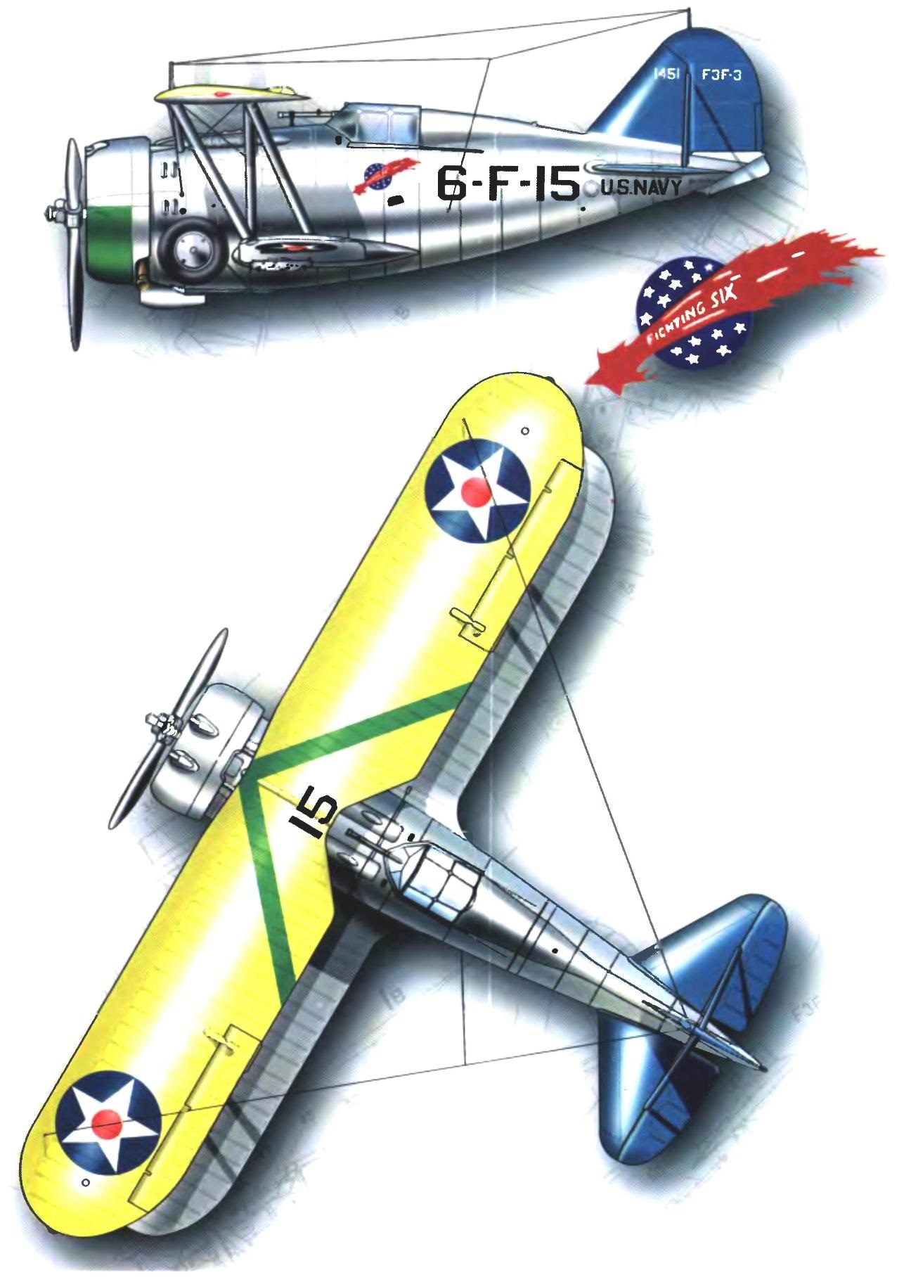
Fighter F3F-3 from the squadron VF-6. August 1940
The wing fighter was solid wood. The area of the biplane box was from 24,21 m2. By construction, the upper and lower wings were identical — both had two-spar box-type. The lower wing was attached to the second and third force the frames. Rigidity single and biplane box wing is further provided with profiled belts-braces. The upper and lower wings between a connected N-shaped strut.
Longitudinal power set of the wing was rib truss assembled on the glue. Additional rigidity to the wing — upper and lower — ensured internal cable braces. The entire surface of the wing had fabric covering. Ailerons were located only on the upper wing and had a power set duralumin and fabric covering. Control ailerons — hard.
On the left console lower wing mounted retractable landing light. On the bottom of the wing consoles could be installed two MK XLI bomb rack under the bombs of MK IV.
The tail Assembly was an all-metal power set. Stabilizer and fin were trimmed with duralumin sheets and rudders and height of the canvas. The installation angle of the stabilizer can be changed by using the knob located on the left panel of the cockpit.
The rudder was mounted trimmer to compensate for the effort on the pedals of foot control. Rudders — flexible cable. To ensure greater rigidity of the tail stabilizer and fin connected between the profiled struts. The hinge of the rudder and the height is covered with spring-loaded lids.
Fighter chassis — tricycle, tailwheel. System retract landing gear — hydraulic, with the possibility of a mechanical emergency release manually. Control of the landing hook is also hydraulic. The main chassis had a system of cleaning that are typical for carrier-based aircraft of the mid-thirties, produced and engineered in the United States, in which the strut and wheel were involved in special niches in the lower part of the fuselage. Svobodnodispersnye the tail wheel retracted into the fuselage in flight. Amortization of landing gear — maslanopodobnaya.
The power plant of the aircraft consisted of nine air-cooled engine company Wright R-1820-22 CYCLONE power 950 HP Engine was completed all-metal three-bladed variable-pitch propeller right hand rotation with a diameter of 2740 mm. engine Start is carried out from an onboard battery. The exhaust gas was diverted to a common manifold from which two of the exhaust pipe output into the atmosphere. Hood the streamlined shapes such as NACA completely covers the entire engine and reduced aerodynamic drag.
Fuel contained in two fuselage fuel tanks— mostly — with a capacity of 314 liters located between the first and second power frames, and more — with a capacity of 178 liters, installed at the bottom of the fuselage between the second and third power formers. On top of the fuselage housed the 34-litre tank.
The aircraft was equipped with a fire protection system. Armament of the fighter consisted of two synchronized machine guns of the type Browning MK.2. Left front cockpit was mounted 7.62-mm machine gun with an ammunition load of 200 rounds, right 12.7 mm machine gun with an ammunition load of 50 rounds. Ammunition was placed in the cartridge boxes. Supply of ammunition — belt. On the lower wing provided for the installation of two bomb racks under XLI Mk bomb MK IV caliber to 116 pounds (52.7 kg).
Flight characteristics of the GRUMMAN fighter F3F-3
Wingspan, mm………………….. 9750
Length, mm………………………………7100
Height, mm…………………………….3170
The wing area, m2……………………….24,15
Maximum speed, km/h……………………….390
Cruising speed, km/h………………………..241
Practical ceiling, m………… 9204
Flight range, km……………..1327
Empty weight, kg……………………. 1477
Maximum takeoff weight, kg………………. 2042
Armament:
— 1 machine gun 7.62 mm
— 1 machine gun 12.7 mm
— 2 bombs caliber 52,7 kg
N. Food reserve was, A. CHECHIN, Kharkov
Recommend to read
 ON THE “TRAMP” – IN CYCLING
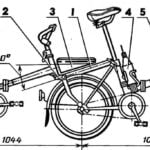
Our family vehicle — a three-wheeled velotandem "the Vagabond" — designed by me for tours. From the same konstruktsii it is distinguished by the absence of any irreversible...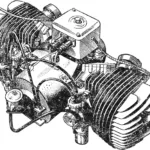 Double-IZh
When building amateur aerosleds, gliders and hovercraft, the greatest difficulty is usually choosing the right engine. Standard production engines often fail to satisfy home‑builders in...
