
 The aircraft belongs to those fields of technology which are developing particularly rapidly. In a historically short period of time, speed, altitude, payload, flight range of the aircraft has increased several times.
 Particularly sharp increase occurred after a powerful gas turbine engines, when a military and later civil aviation has shifted from to sound to supersonic speeds.
A significant increase in velocity and as a consequence an increase in the landing run has put forward a lot of difficult challenges to designers and operators. If piston machines have enough flat area at 700-800 m with grass, require reactive concrete takeoff / landing runways with a length of over 3 km. Their construction involves huge costs. Before the designers raised the question: how to reduce landing run? One of the most promising ways is to create aircraft with vertical takeoff and landing (VTOL). These machines can give great savings in the construction of airfields, to expand the scope of aviation, and the military — to give high mobility and stealth.
In 50-ies in the United States came to light experimental aircraft XFY-1 (Fig. 1), it was first made a vertical takeoff and landing and transition to horizontal flight. Its two gas turbine engines with a capacity of 2630 HP rotated through a common gear, two coaxial screw Ø 4.9 m, developing take-off thrust up to 9 thousand kgs at takeoff weight of 6800 kg. Such ratio values enabled the aircraft to climb vertically with a speed of 30 m/s and after the transition to horizontal flight to reach the speed of 800 km/h. By construction, it was a “tailless” with a triangular wing and the keel, the ends of which established four landing gear that allowed at the start to put the car upright. The seat of the pilot. Bent forward by 45° and returned to its normal position relative to the fuselage during the transition to horizontal flight.
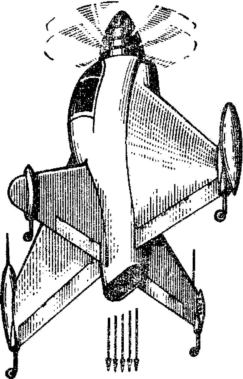
Fig. 1. Experimental aircraft XFY-1.
The plane flew to a height of 60-70 m, and then using aerodynamic handlebars he was given a forward tilt, with the increase which increased the speed and the car shifted into horizontal flight. When landing, the plane was nose up, took a vertical position, the engine was saularis momentum, and XFY-1 tail down sat on the ground. Ruled the unit on take-off and landing modes the elevons and rudder, located in the powerful air stream which is discarded screws.
The problem of safe landing (with engine failure) on the XFY-1 was carried out as follows. Ahead of the screws was installed fairing stowed in his cargo parachute. Pressing the button was enough that in an emergency situation, triggering the explosive charge and the parachute is thrown up. In his design there was a special cargo, which resisted the downward production the air flow from the screws and contributed to the almost instantaneous opening of the dome. The lower vertical tail could be separated from the aircraft, which gave the opportunity to make an emergency landing for engine failure in level flight.
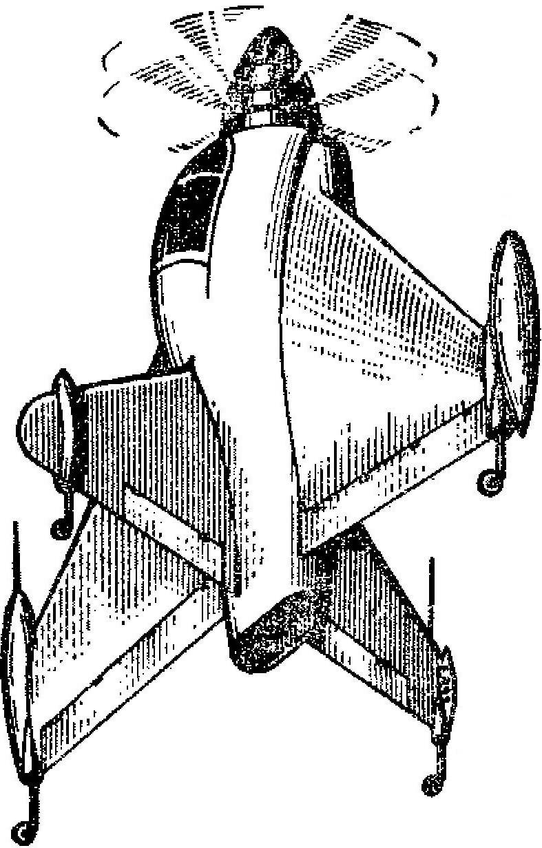
The original unit of the same class, called “Coleopter” (Fig. 2), was created in France. The peculiarity of it — annular wing in the form of a hollow cylinder Ø 4 m, inside of which four struts attached to the fuselage. In the bow was the cabin of the pilot; behind her stood a turbojet engine. At launch the device was controlled jet rudders, and when it reaches high speeds — with deflected surfaces on the ring wing.
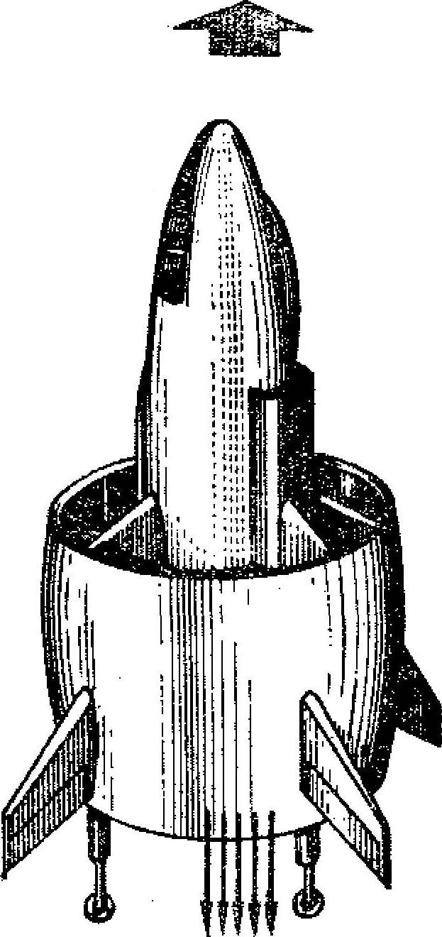
Fig. 2. “Coleopter”.
Aircraft of this type was, of course, unsuitable for passenger and cargo transportation, their use for military purposes had been hampered due to the complexity of operation, besides the control system on the hover mode was unreliable, because their design did not go beyond the experiment. All of the built VTOL vertical position of the fuselage at the present time does not fly neither.
Was “run-in” scheme for VTOL aircraft in which the lifting devices were used fan installation. It was attached in a special wing tunnels, their inlet and outlet openings in horizontal flight was closed by flaps or blades of the guides.
One such aircraft was the XFY-5A (Fig. 3) “Ryan”. This cantilever low. The lifting force for a vertical take-off and landing created two installed in the wing fans, which via a bypass damper is supplied a flow of gases from the engine. Located in the forward fuselage fan of small diameter provided in the longitudinal control of the aircraft.
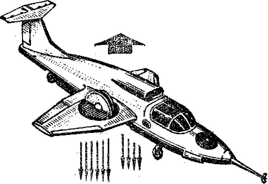
Fig. 3. Low XY-5A.
In the horizontal flight fans closed top flaps, and the bottom controlled blinds, the latter provided the horizontal and vertical components of the thrust vector by moving back the flow of the fans. With increase in flight speed they did all the smaller part of the gases from the engine, until finally the entire thread didn’t start to jump out through the jet nozzles, located on both sides of the fuselage.
In 60-e years on the basis of serial fighter-bombers “Mirage III” in France was established VTOL “Balzac,” which took off vertically with the help of eight lifting engines. They were placed in pairs in four compartments in the center of the plane. Over them were set sash opening at startup. After rising 30 m machine were displayed on the transitional regime, for which the sustainer engine mounted horizontally in the tail section, included at full thrust and lift when reaching speeds of 300 km/h was turned off and the sash closed. The maximum speed of “Balzac” in level flight exceeded 1000 km/h.
Experiments with this machine helped to create the fighter-bombers “Mirage IIIY” (Fig. 4), it developed a speed of 2,400 km/h the Only drawback of this scheme was that on Board the aircraft in horizontal flight, the engines were not participating in the flight and is “dead weight”.
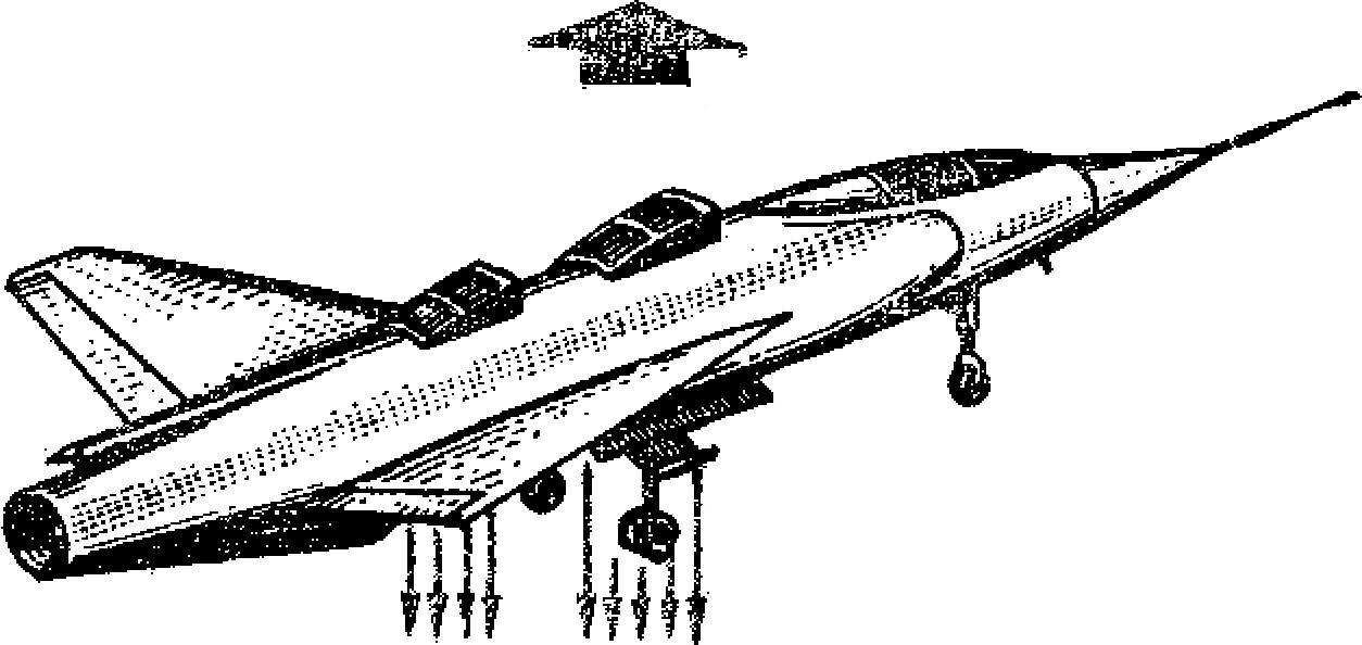
Fig. 4. “Mirage IIIY”.
The appearance of the power plant, which could create both vertical and horizontal components of the thrust vector, gave the opportunity to the English designers of the company “Hawker” to build an airplane, the P. 1127 (Fig. 5). The peculiarity of it was that it had four engines with swivel nozzles (100°). Their outlets were located on the fuselage, two on each side, was covered by a special fairing. With such nozzles, located near the center of gravity of the aircraft; and provide a vertical takeoff. At the altitude they were to turn, and the engine thrust brought P. 1127 in horizontal movement. On takeoff and landing, in transient conditions it was managed by jet rudders mounted in the nose and tail parts of the aircraft. Were they on the wing tips. To create a control force from the nozzles of the produced compressed air which was selected for the compressor of the engine for the piping system. When the machine is switched to horizontal flight, and the nozzles are turned back, automatically shut off the jet rudders and the plane was controlled aerodynamic.
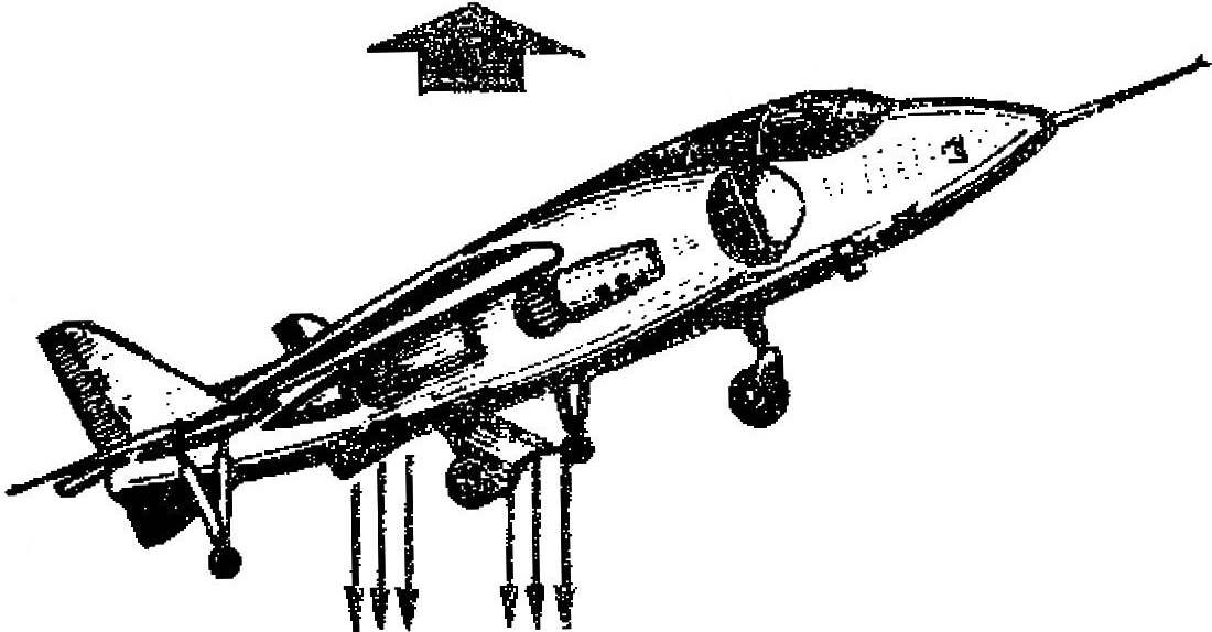
Fig. 5. The P. 1127 Aircraft.
The successful testing of the R. 1127 allowed in 1967 to launch a series of aircraft “Harrier”, featuring a more powerful engine and slightly increased size of the wing and fuselage.
Aircraft with rotary gas flow have a lot of advantages: thrust propulsion is used for vertical, horizontal and transition flight modes; starting the engine check and taxiing aircraft on the airfield are made in the horizontal position of the nozzles, which greatly reduces erosion of a runway and the possibility of ingestion of dust and dirt.
In the Soviet Union was also held and conducted extensive research of schemes of vertical takeoff and landing aircraft. For this was built a flying stand, called the “Turbolet” (Fig. 6), created under the guidance of the designer A. N. Rafaelyantsa. The device consists of a metal farm With the vertical turbojet engine. Next was the cockpit and fuel tanks. Four landing gear provides normal position of the vehicle on the ground. To the ends of four long brackets were installed, the jet, and in the area of the engine exhaust gas rudders, which allowed to achieve controlled flight.
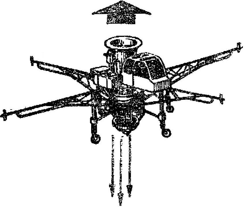
Fig. 6. “Turbolet” A. N. Rafaelyantsa.
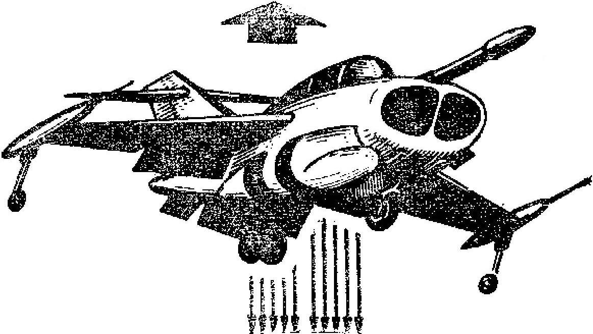
Fig. 7. Fighting the Soviet aircraft vertical takeoff.
And in 1967 on the air parade in Domodedovo hero of the Soviet Union, Colonel Vladimir Mukhin was demonstrated in flight, the first Soviet military aircraft vertical takeoff and landing (Fig. 7). This car had a jet engine and a device for deflection of the jet exhaust.
Currently, schemes of devices of vertical take-off and landing are very diverse and depend mainly on their purpose.
E. KORNEEV, an engineer
Recommend to read
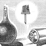 SIMPLE SPRAY
To fully exhaust aerosol spray can, which is usually just thrown away, there are wonderful sites: valve and spray head. The latter, for example, can turn into a spray of ordinary rubber...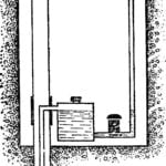 WATER IN A COUNTRY HOUSE
It is difficult now to imagine urban and rural life with no running water. Well, if the centralized water supply there, and the next well, the simplest solution is to use to lift water...
