Within each trench for the laying of the formwork is nailed (line, rope) two rows of wooden pegs with cross-section 50×50 mm, 6 pieces on each side of the trench. The distance between the pegs should be equal to 210 mm in width and 1000 mm in length of the trench; rows of pegs are spaced at equal distances from the ends of the trench.
Fig. 4. Foundation:
1 —trench; 2 — the pegs of the casing; 3—concrete; 4—formwork, and 5—foot stakes; 6—lag;
With the inner sides of the pegs of the casing boards are nailed, the bottom of which is at a height of 200 mm from the bottom of the trench. The distance between the inner planes formed by these boards should be 150 mm. Additional rigidity of this design gives a number of supporting pegs nailed in an inclined position in relation to the primary; thus strengthened the base of the formwork can withstand based on his logs, which are placed simultaneously with the concrete pour.
Lagi section 200×80 mm are arranged on the upper edge of the internal boards of the formwork and are aligned strictly horizontally. The distance between axes a log should be 600 mm except for the extreme lag, where the distance is 530 mm. the Total length of the lag corresponds to the distance on the outer faces of the walls, that is 3600 mm. the Upper plane of the base should be flush with the edges of the boards nailed between the joists at half their height. When pouring concrete it is necessary to make sure that it has not exceeded this level and has not spread on the walls of the formwork. The formwork can be removed after a few days of hardening concrete.
THE FORMATION OF THE FRAME HOUSE
The frame elements can be prepared in advance and transported to the site entirely or assemble it on the spot. Figure 3 shows a General view of the frame of the house. It shows his base — joists from timber 200x 80 mm; at their ends are laid from tying beam cross-section 80×60, upon which corner and intermediate uprights.
Corner rack — made of timber 150X 150 mm; on the upper ends of their chosen quarters of the size of 150×100 mm and the bottom 120×80 mm. In the upper quarter part of the bolt — beam dimensions 4700x150x150 mm, which connects the corner posts being attached to them the ends (roughly) with a few screws or nails. The bottom quarter corner racks are designed for strapping.
Other racks of a skeleton shot down three boards 80 mm wide and 20 mm thick (see Fig.W, bottom). The total length of the column accurately corresponds to the distance between the horizontal elements of the frame. However, the middle Board (of the three components of the rack) shortened by 40 mm from each end, forming grooves. This construction provides a strut with insert it into the grooves in boss size mm. 200x40x20 boss fortified in the groove formed between the outer boards, outside section stands on both sides and is nailed to the banner (and above the bolt) and to the rack.
Door and window boxes shown in the figure by a dotted line; their installation will be described below. Corner and intermediate uprights connect box door with strapping and bolt. Has your stand and window box.
Figure 3 shows the location of five of attic trusses, which is a roof (a structure discussed below). Their items are also put together from three planks with cross-section 80×20 mm, which provides ease of connection of the elements among themselves, and their connection to the uprights of the back and side walls.
Fig. 3. Frame building:
1 —rail; 2—lag; 3 — angled front; 4 — intermediate racks; 5—bolt; 6—lug; 7 — front strut trusses; 8 — struts farms; 9—mounting the corners
Middle Board in the three intermediate frame uprights of the back wall under the three intermediate trusses to contact them in the upper part and is extended above the other two boards; and a bottom formed groove of the boss will install them on the harness. To last these racks can be attached another, and metal plates, which ensures additional safety of the stands.
The intermediate rack frame side walls also comprise three boards, making them easy to bond with extreme trusses and strapping. All of these elements when installed in place require supporting fastening: temporary struts to hold them to the wall in a vertical position.
Five attic trusses roof made of boards 80×20 mm; all elements are United also of three boards in different combinations. Rafters (upper sloping elements) and the tightness of the farm (see Fig.1) are connected at the back wall. Between them the three struts, two vertical and one oblique (located on the facade). This connection creates a certain shape of the roof. On inclined racks are made exterior sheathing of the attic Groovy boards.
To strengthen the joints of the rafters and tighten and unite all the farm, they nailed the reinforcing Board. The struts of the trusses (see Fig.S) from boards 80×20 mm reinforced between racks, providing additional rigidity to the entire frame of the roof. In the extreme inclined strut trusses are duplicated on the front side of a Board cross-section 80×20 mm.
Mounted farm on the facade, relying on a corner stand and bolt. Mount farm is metal corners (see Fig.H), and the deadline is still plates on the bolts from the outside needs to be recessed so as not to disturb the casing of asbestos cement sheets. The struts are shown in figure 3, provide vertical girders, which are nailed to their desks.
Fig. 5. Options “tongue and groove” connection of the frame elements and girders, consisting of three boards
The intermediate rack frame side walls includes a gap between the boards that make up the extreme tightness of farms, their average Board. Stand the rear wall connects the top reinforcing Board is 80×20 mm; it is located in the corner formed by-
The roof is laid on the sheathing boards 80×20 mm, laid across the trusses and nailed to the rafters. The intervals between these boards depend on the dimensions of asbestos cement sheets which should be laid on the crate. The roof edges has a slouchy fit, sew up the boards for windbreaks.
Door and window
Box door going from triple boards 80×20 mm. Two carton Board shot down flush, edge-to-edge; and the third nailed with a space of 3 cm: thus is formed the quarter, which includes the door leaf. This same Board on the ends of each vertical element of the box is longer than the other two, allowing you to fix the box on the harness and bolt.
The horizontal elements of the box also consists of three boards; one of them is indented, forming a quarter; and on both ends of it projecting beyond the other, playing the role of a stud for connection to the vertical elements.
The door leaf rally of the grooved parquet plates. Needless to say, the width of the door must correspond to the distance in light between the elements of the box with a gap of 10 mm. the Door is hung on conventional hinges and are supplied with lock.
Window box is composed of vertical elements, connected by horizontal. Each of them consists of three boards with dimensions of 80×20 mm. vertical elements — all three Board the downed edge to edge, while the middle Board on both ends shorter than the other two boards for the formation of grooves. Accordingly, in the horizontal middle Board is longer than the others and as a spike is designed for coupling with vertical elements. Horizontal can have a special cross-section: the two rear components of their boards are slightly shifted upward relative to the third. This location allows you to set the tilt
The shutters on the Windows, and the door made of parquet boards, solid two horizontal and one inclined Board.
Roofing & siding
Applied roofing asbestos cement corrugated sheets with a big step waves. Their attachment to the crate, Packed on farm, is performed by using roofing nails. Waterproofing under the sheets of special plastic panels, roofing felt or roofing material.
Flat asbestos sheets used for exterior wall cladding. They are applied directly on the frame and nailed with galvanized nails. The leaves close the front surface of the house only partially, and the rear and side walls completely, including the triangle of the far farms. Side of the last one could close of boards, as on the front of the inclined struts farms — it would look even more beautiful.
Interior finish of walls and ceilings — of plasterboard sheets. First and foremost, sheathed the roof, the sheets are nailed to the boards, connecting the tightening farms. Thermal insulation layer (absolutely necessary) — glass, placed it on the sheets gradually, as progress on the hull. So gradually laid and insulation between the outer and inner covering of the walls, until the leaves are attached to the uprights.
The floor is laid on joists to wall cladding. Gipsokartonnye sheets that make up the sheathing, nailed to the uprights and backing bars (lugs) attached with screws to the floor in the spacings. Baseboards and layouts complete finish.
Recommend to read THE BAYONET EVEN SHARPER However, it can be made more versatile if the blade is cut, as shown in the figure. This more acute wedge-shaped version of the shovel is easy even in the most dense, parched soil. PARANORMAL In the family of PEUGEOT has a car class. Your first car, Armand Peugeot in collaboration with Leon serpolle built in the nineteenth century — it was heavy and bulky three-wheeled carriage...

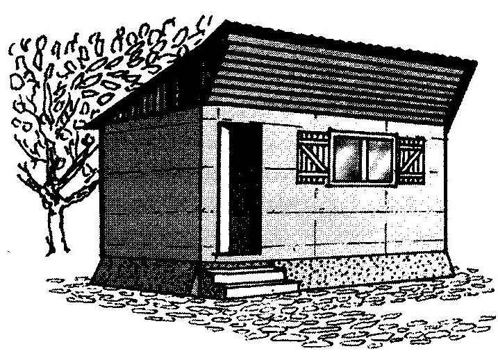 This house (Fig.1) with an area of 17 m2 consists of one room (see Fig.2) and may serve as a temporary shelter during the development of new suburban area. It is designed for four people — two adults and two children. The basis of its design is the frame (Fig.H), sheathed on the outside with asbestos cement sheets — flat for walls and wavy roof. Plasterboard going on the inner lining. Between the outer and inner covering of the walls and ceiling laid glass wool, which serves as an insulating layer. Design rests on the two tie concrete blocks that serve as the Foundation (see Fig.1 and 4).