“DISAPPEARING” STAIRS

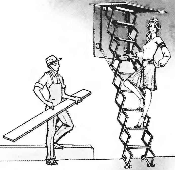
A lot of trouble delivers the design of internal stairs, for example, the attic. For convenient large marches, as a rule, not enough space and they are very steep, which is dangerous, especially for older people.
In one of the rooms of the old Czechoslovak magazine offered a curious compromise that we present to our readers. Down, this design resembles a regular staircase, with steps which are quite comfortable to climb. Folded as it rises and does not occupy much space, face the horizontal “door” leading to the attic. The whole design operates the motor, turn on the bottom button.


The “door” on the ceiling

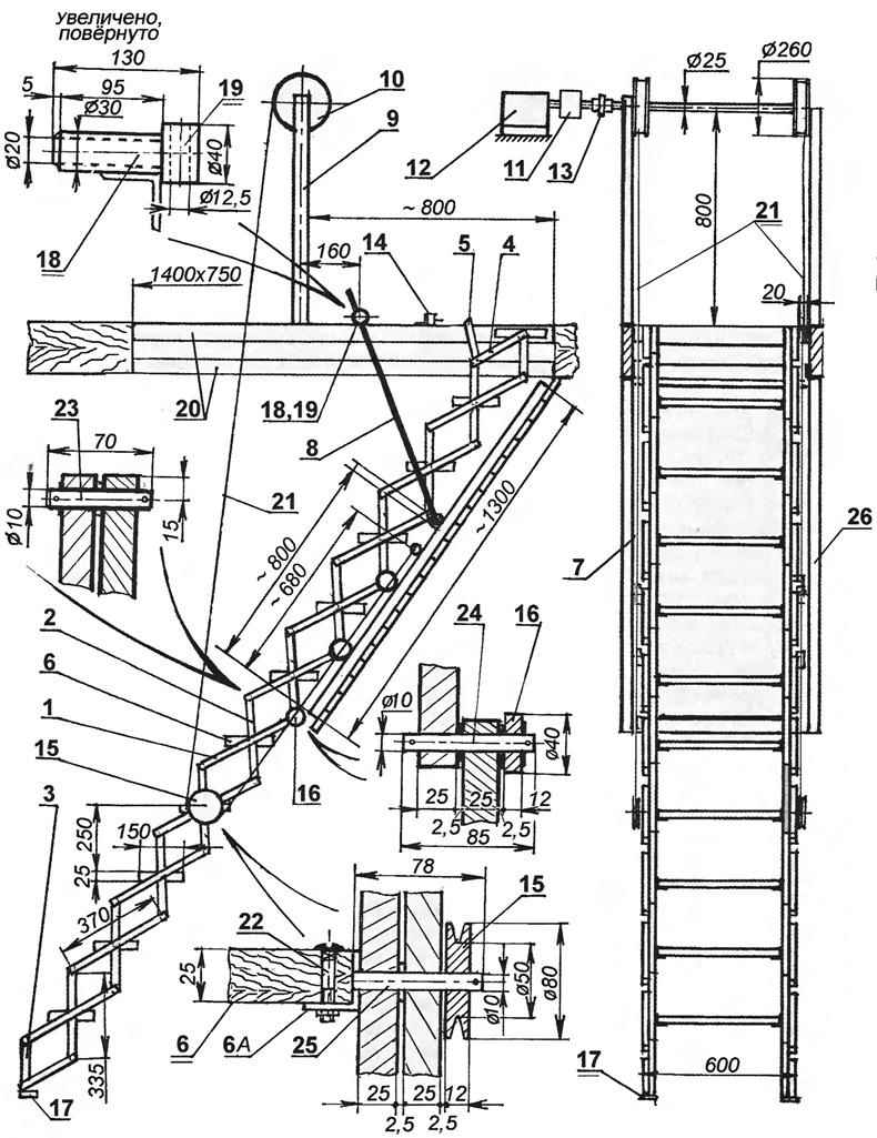
Some design details we deliberately do not show, as they will still be made locally. Anyone, therefore, who undertake the implementation of this idea, must have a certain technical skill, and here is the drawing (Fig.1) gives the necessary General picture of the structure and its main nodes.

The attic hatch, as a rule, the roof construction is usually already there. Therefore, for stairs with a width of 600 mm will be required to produce his frame size mm. 1400×750 Board it required to be strengthened. For this it is necessary to use steel angles dimensions 50x50x3 mm, which are welded two identical frames (20): one is mounted on the hatch top, the other from below and then the frame welded together or screwed with screws to the sides of the hatch.

1. Mechanized attic stairs

1. Mechanized attic stairs:

1—long arm foldable frame ladder (outer pipe 25x25x2);
2—short arm of a skeleton (inner pipe 25x25x2);

3,4—cropped (end) the levers of the frame of the ladder;

5 —the lever of the limit switch of the motor;

6—step (6A—her support);

7—tubular rails for rollers of the ladder frame (2 PCs.);

8—tube-limiter (2 PCs.);

9—front drive drums (2 PCs.);

10 drum drive (2 PCs.);

11—worm drive mechanism;

12—motor;

13—clutch drive;

14—limit switch;

15—a pulley of the ladder;

16—skating rink stairs;

17—lower limit switch;

18—axle;

19—a cylinder (or bearing);

20—framing the niche of the hatch (frame from steel angles);

21—a rope (rope);

22—bolt stairs;

23 —the axis of the levers stairs;

24—axis rollers stairs;

25—the axis of the pulley;

26—frame shield “door”.


Frame shield doors (26) is also from corners, but for this purpose you can use the corners of the smaller sizes 36x36x3 mm, and the size of the “door” with the parts of the pick up so that she was in the frame of the hatch with a gap (on the perimeter) of at least one centimeter. In frame “doors” later, in the final stage of the work, instead of a shield, you can insert a Board or plank, but now you need to attach to the frame two tubes (7) size 70x35x2,5 mm is the “rails” along the long sides of the “door” (10 mm from the surface). The door should turn on three (100×100 mm) door hinges, one half of which need to be screwed to the narrow Board of the hatch.

Ladder

A fragment of a ladder when liftingThe main material used for the manufacture of stair components, is a closed steel pipe profile 25x25x2 mm. Tube should be cut on separate levers of the two dimensions: “horizontal” segments (1) with a length of approximately 400 mm, and vertical (2) about 365 mm. (the Number of segments depends on the distance between the floor and ceiling. For example, at a height of 3.5 m is sufficient to prepare 20 segments). At the ends of the ladder top and bottom are attached by four shortened lines (3, 4) whose length is approximately 200 mm and 182 mm.

Each middle arm of the ladder drill three holes with a diameter of 13 mm: two edges and one in the center. These holes need to weld washers internal diameter of 13 mm and a thickness of 1.5 mm. the Ends need to be brewing, but these operations can be omitted.

In the sleeve (or hole) to insert metal rods (axis) with a diameter of 10 mm, which are pre-cut: to link the pair of levers — with a length of 70 mm (23), for fastening steps 78 mm for the connection of a ladder frame — 85mm (24) finally, for fastening the levers in the ground, “rope” rollers — 78 mm (25). For fixing the axes at their ends drill holes 3 mm, where we insert the cotter pins, and between the levers — washers with a thickness of 2.5 mm.

Fig. 2. Drive the mechanized stairs

Fig. 2. Drive the mechanized stairs:
1 —engine;

2—the worm gear;

3—reel;

4—rope (cable).


Guide wheels (16) mounted in place of the fourth, fifth and sixth joints. They can be made of rigid plastic, but can use ready-made wheels such as a baby stroller. Tube (25) that will keep the step (6), weld the short levers or the parts (6A), and so that when lowered the ladder rung would be horizontal. In addition, in these parts (6A) and the steps you need to drill 6 mm holes through which bolts (22) are attached to the steps themselves.

One of the joints of the levers of the ladder is mounted guide roller (15) for the lifting cable (21). Other sizes of the fixing roller will change. It should be in such a position that when the cable tension was first the stairs, and after full folding needs to get up “the door.”

The stairs still need to install two guides (or restrictive) of the tube (8) with a length of approximately 900 mm and a diameter of 12 mm. the Lower end of these tubes is attached to one of the joints of the levers, and the other is upstairs pulley, for which you need to cut the M12 thread and screw the trunnion (18) with hole diameter 12.5 mm. On the axle made in the form axis, you must put on a rotating cylinder (19) or bearing, which will ride on the side of the hatch. The axle should be mounted on the pipe so that the ladder when opened had the inclination to 50°.

Drive

This work is, in principle, over — stairs can be used. However, the nomination and climb the stairs manually would have been quite uncomfortable, so it is advisable to Supplement the design of the electric drive.

Drop Drive system for a winch hoist of the stairs is rather difficult. It uses the electric motor (12) with a power of 0.8 kW. The axis of the motor drives the worm gear (11) from coupling (13) which when lowered ladders provides the necessary braking, and after the upgrade — fixed in the upper closed position. Knowing the gear ratio of the worm gear, the size of the winding drums must be selected so that the cables moved at a speed of up to 5 — 6 meters per minute. The engine is installed on a special rack or the beams of the attic. Winding drums (10) and strut (9) must be positioned so that, walking up the stairs, under them it was possible to pass. The drums on the axle mounted on bearings.

The electrical circuit must provide protection for the engine, changing the direction of rotation and automatic disabling it in the extreme positions. The first task is performed by the fuse 25 ampere three-pole switch 16 amp. To change the rotation direction, using electromagnetic switches, which are changing the phase will change the direction.

The limit switch 14 on the frame of the hatch is activated from the lever 5. The second limit switch (17) must be positioned on the leg of the ladder so that it operates by lowering the stairs.

When working with electric current do not forget about safety precautions and best if all the connections will perform specialist.

Recommend to read

  • TO PLANT POTATOES? WITH PLEASURE!TO PLANT POTATOES? WITH PLEASURE!
    Many farmers dream of a mini-tractor. It can be purchased in the store or do it yourself. But the benefits of a mechanical assistant would only be the case if it comes with tools that...
  • INFANTRY FIGHTING VEHICLE BMP-2INFANTRY FIGHTING VEHICLE BMP-2
    In the late 1950's — early 1960-ies there has been a backlog of the USSR from Western countries in the creation of heavy tracked armored personnel carriers. During this period in the...