Free energy wind has long serve man. Question about using it is urgent and now, especially with the ever increasing shortage of natural fuel. There is a “demand” for it and the private sector, as evidenced by letters submitted to the editor.
So, Evgenie Osipov from the village Nikolaevka of the Bashkir Autonomous Soviet socialist Republic wrote: “I’m a carpenter by profession, have their infield. The whole family works, and the night in the summer season, watering the garden do not have time to stock up on water from a well. And she needs to be a certain temperature, at least a little warm. To leave the air pump when no one is home, not because of the risk of fire. It would be best to build a low-power metronidazol installation”.
In this and the 3rd offer published description wind water for marginal wells HOMESTEAD farms. E. Makarova from Karaganda has received a copyright certificate N° 866265. The design uses the original principle of delivery on top of the water using the “endless” absorbent tape, from which it is then pressed with a roller with a counterweight.
Wind — engine of this installation; propeller blades — the propeller. On the shaft of the latter and water is the Transporter: a continuous belt of porous material, the bottom of which is lowered into the well. Spinning the screw stretches the tape up, lifting the soaked water. It selects compacting roller — water flows down a drain pipe to the feed tank. The verticality of the tape — slack — is provided in its bottom with a tensioning mechanism to be constantly immersed in water.
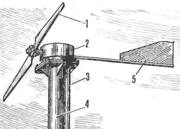
Fig. 1. Water installation:
1 — propeller, 2 — actuator, 3 — drain pipe, 4 — tower setup, 5 — stabilizer, 6 — test tube 7 — feed tank, 8 — supply pipe, 9 — tensioner mechanism 10, the tape”the Transporter”, 11 — the well.
Fig. 2. Structural diagram of water:
1 — a casing of the drive mechanism, 2 — bushing, rack shaft, a 3 “shovel” stabilizer, 4 — tube stabilizer, 5 — base, 6 — shaft, 7 — roller, 8 — body drive mechanism 9 is the drive roller 10 the tape”the Transporter”, 11 — tensioning mechanism, 12 — tensioning roller 13 is the frame base 14 is clip of the squeezing device 15, and the counterweight 16, the axis of the cage of the squeezing device, 17 — inlet, 18 — drain fitting, 19 — the axis of the pinch roller.
Fig. 3. The propeller:
1 — sleeve, 2 — pinch bolt M8, 3 — retaining cheek, 4 — blade propeller.
Two-bladed propeller has a length of 2000 mm. Wooden blades mounted on a metal sleeve with mounting cheeks and STA””-nymk bolts. The sleeve coupling on the shaft keyway with a lingering nut M16.
The stabilizer automatically sets the screw against the wind. Guide “shovel” stabilizer cut from steel sheet of thickness 1 mm. For her in the carrier pipe Ø21 mm propisyvaetsya longitudinal groove where it is inserted and fastened at the ends of the two through rivets Ø5 them. To the pipe — at the very beginning prepariruetsya heel. It has two holes for bolts M8, for connection with the base of the drive mechanism, and another hole Ø25 mm, in which, when the Assembly includes a flared upper part of the finger support rollers.
The screw shaft installed in the sleeve of the strut drive mechanism in nylon bearings from the shaft end wearing lead rubber roller, through which is spanned by the ribbon conveyor. The base of the mechanism is rotated relative to the housing on a support home. In case this is done the annular groove. Card base is cut from sheet metal thickness of 2 mm. it drilled holes Ø15 mm for the fingers of rollers, the Assembly fingers inserted into these openings and resultsbecause. Clips recorded pressure washers. In addition, the basis for the admission of the tape cut a rectangle with sides 110 X130 mm. Next to him, welded to the frame under the axle of the cage is a squeezing device. On the one hand in the cage is a concentric slave cylinder rubber cushion, the other on the rolled axis of the counterweight, with which the roller is pressed against the ribbon, “extracting” the water. Under them put a rubber visor — receiving waters. The drive mechanism is covered with a top cover, which can be made of sheet metal.
Tensioning mechanism pulls the tape down: for this he metal weighted puck weighing about 2 kg, attached to the cage tension pulley bolt M10.
Fig. 4. Stabilizer:
1 — foot rod, 2 — rod, 3 — “shovel”, 4 — rivet 5.
Fig. 5. Strut shaft:
1 — shaft sleeve, 2 — korenovy bearing, 3 — bearing.
Fig. 6. The base of the drive mechanism:
1 — charge, 2 — frame base, 3 — finger support rollers.
Fig. 7. Clip of the squeezing device:
1 — frame axis of the squeezing roller, 2 — axis counterweight.
Fig. 8. Tensioning mechanism:
1 — a tension roller, 2 — axis, 3 — yoke, 4 — load, 5 — bolt M10.
Tape is a rubber strip with a thickness of 3-4 mm, it pasted foam thickness of 15-20 mm. the two layers are connected to an oblique junction. Tape can be used and the sponge rubber. Frame lift and feed tank (tank) are made from scrap materials, and mounting height should be selected such that the tensioning mechanism was always in the water.
It is possible to execute a number of works, for example, to water the garden, directly at the working windmill, but easier to store water for future use, filling the tank, where she is warmed by the sun. Installation you can easily insert without supervision. Even if the water is overflowing the capacity, it will drain back into the well through the choke tube.
Wind lift can provide “production” of 100 m3 of water per day.
There would be only the wind!
E. MAKAROVA, Karaganda
Recommend to read PASS / FAIL If you doubt the validity of a diode, transistor or want to determine their conductivity type, use one of the devices with which we introduce you in this article. The advantage of the... THERMORESIN FOAM If you have a rectifier for charging automobile batteries, a step-down transformer or Latr you will be able to make thermoresin cutting foam. The cutting part is a piece of nichrome wire... 
 Free energy wind has long serve man. Question about using it is urgent and now, especially with the ever increasing shortage of natural fuel. There is a “demand” for it and the private sector, as evidenced by letters submitted to the editor.