When reaching the required pressure in the accumulator which is determined by the required supply of water in the pressure switch will shut off the pump. Once the pump is shut off, the compressed air from the receivers will force water from the pipes in the well. The water and air non-return valve remains in the pressure tank and the pipes. After several reviews of water air from the accumulator will Strajitsa into the atmosphere. The next time the pump running water up to the point A will remain the same as described above, and after the accumulator will be pumped only water (no air). Crane 6 is used to drain water from the system, bypassing the check valve. It is necessary to open the taps of all consumers. During long-term operation of water supply the amount of air in the line to the point And may be reduced due to the absorption of water, which will lead to incomplete ejection of water from the pipes. Therefore, periodically, about once in four or five days you must open the tap 8 at idle the pump for complete removal of water from the receivers. So the pump does not turn on, preferably next to the crane 8 to have further power switch of the pump.
Fig. 1. The General scheme for supplying water to the house:
1 – barrel well; 2 – inner insulation; 3 – external insulation; 4 – inlet flange; 5 – pit; 6 – protective tube; 7 – wall; 8 – a seasonal heated indoor
Fig. 2. Device home water supply:
1 — well; 2 – a flexible hose; 3 – centrifugal submersible pump without non-return valve; 4 – pipe; 5 – valve; 6-faucet; 7-receiver; 8 – faucet; 9 – manometer; 10 – pressure gauge; 11 – the cold water tap of the consumer; 12 – pressure tank; 13 – cable pump
Fig. 3. The pipes in the well:
1 – metal fitting made of brass or bronze under a hose with a diameter of 0.5″; 2 – polypropylene area 0,5″; 3 – polypropylene pipe 0.5″; 4 – durotomy hose to 0.5″; 5 – barrel structure (concrete); 6 – gasket (silicone sealant); 7 – flange (сталь3); 8 – gasket (silicone sealant); 9 – collet coupling for polyethylene pipes with a diameter of 0.5″; 10 – steel pipe 0.5″
Look at the water on a concrete example (Fig. 2): the distance from home to the well – 10 metres; maximum distance from the point of connection of flexible hose to the pipe up to the surface of the water is 3 meters; the supply to the house pipe and tubing have an inner diameter of 16 mm. Determine the minimum amount of receivers /Rmin . The maximum volume of air in the hose and pipes to the check valve /in is determined by the known formula:
Vin = (PD2/4)L, (1),
where D is the inner diameter of the hose and the pipe, L is the distance from the water surface to the check valve (10+3)х102 (see – for ease of calculations).
Thus,
Vin =0,8×1,62х13х102см3 ≈2,6х103 (cm3 , or about 2.6 liters). Consequently, the capacity of the receivers should be more than 2.6 liters. As the receivers used two series-connected body from the filter “Aquaphor” (or “Geyser”) no cartridges. In this case, the receiver volume is about three liters.
Determine the minimum value of the pre-generated pressure in the accumulator Ramine .
As noted earlier, this pressure must be greater than minimum pressure in the receiver RRmin created with the full displacement of air from the hose and the pipe, i.e.:
RAmin ≥ RRmin (2).
It is known that the product of the gas pressure on its volume in the closed space is constant, i.e.
VxP = CONST (3).
From this it follows:
5,6×1 =3хРRmin ,
where: 5.6 l (3+2,6) – total volume of air in the air chamber and in the pipes before compression, 3 l – volume of compressed air in the receiver without water.
Thus, RRmin ≈1.6 ATM. Given (2), take RRmin ≈ 1.8 ATM.
3. Define the nominal pressure in the accumulator PAnom .
RAhn – this is the pressure at which the accumulator filled with the required volume of water (e.g. 2 liters). Use industrial pressure, the volume VA = 8 litres. From the formula (3) follows:
RRmin x8= Ramine X6,
where 6 is the volume of air in the accumulator after the injection of two liters of water. Thus, RAnom ≈ 2.4 ATM. take RAnom ≈ 2,6 ATM. So, calculating the values RAmin and RAnom , we determined the magnitude of the threshold actuation pressure sensor. The pressure at which happens off the pump, must be of 2.6 ATM, and the pump is 1.8 ATM. Therefore, the hysteresis pressure setting has a value of Δ = 0.8 ATM. Settings pressure sensor is performed at the factory manual on it, while control is performed by a pressure gauge 9 (Fig. 2). From the above calculations it follows that in this water you need to use a pump capable of creating a water pressure of more than 2.6 ATM. Such pumps can be, for example, “Aquarius” or “Trickle” that can raise water to a height of 30 meters and above. At a greater distance from the well to the house and the larger diameter inlet pipes (as opposed considered) it is obvious that the volume of air in the pipes will increase, hence the need to increase the volume of receivers.
Next, we consider some features of the design of my plumbing. To prevent freezing of the top layer of water in the well, and hence the formation of ice plugs in the hose, the trunk is well insulated from the ground surface to the flat top with two layers of polyethylene foam with a thickness of 8 mm (Fig. 1). The upper part of the head covered with a foam thickness of 50 mm pipes in the house and other elements of the design depicted in Fig. 3.
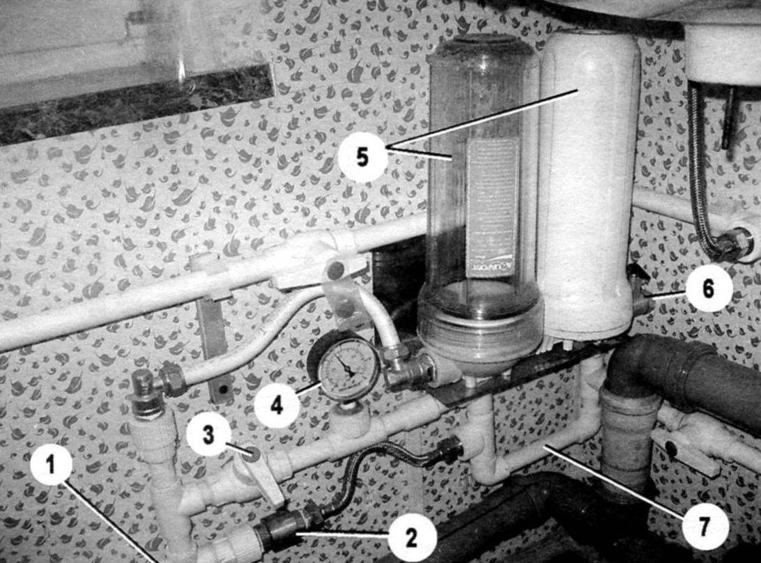
Fig. 4. The receivers:
1 – pipe of the pump; 2 – valve; 3 – valve to drain water from the system to the bypass valve; 4 – manometer; 5 – receiver; 6 – tap for complete removal of water from the pipe; 7 – a pipe to the input of the accumulator.
Fig. 5. Accumulator:
1 – nipple to create excess pressure; 2 – accumulator; 3 – adjust the pressure difference to enable and disable the pump (hysteresis); 4 – a regulator of the pressure at which the pump shuts off; 5 – steel check valve
The approximate dimensions of the flange shown in Fig. 3. Area for hose manufactured in the following way: the fitting 1 is heated to a temperature of ≈ 150°C, after which the threaded part vplavlyatsya in area 2. Polypropylene parts are connected by soldering. The pipe from the well to enter the room of the house insulated with standard foam pipe insulation and placed in a sewer pipe made of polyethylene diameter mm. 110 in addition, for ease of installation, the flange is placed in the pit, lined with brick and the closed wooden lid. The layout of the plumbing in the house is made of polypropylene pipes with a diameter of 0.5″. The valves 6 and 8 – ball.
At installation in the home of consumers used a flexible liner. Particular attention was paid to avoid formation of the so-called “siphons” that prevent the guaranteed drain water from the pipes when you disconnect the plumbing.
For hedging in case of freezing of the inlet pipe I used a self-regulating heating cable from floor heating with 150 watts. The cable attaches to the pipes inside the insulation with aluminum tape and may be activated when a disaster occurs manually. However, for the half year operation of such a necessity has not arisen.
V. IVANOV
Recommend to read PORTABLE BUT DURABLE The bed design is offered to the readers of the magazine, outwardly differs nothing from the purchase, but has dignity, and to connect that our furniture industry is still unable... UAZ HUNTER Ulyanovsk automobile plant has started to update the model range of cars produced in the First stage of this event was the release of the car UAZ HUNTER ("Hunter") is an honored veteran... 
 I want to share my experience in the construction of the winter water supply for periodically heated garden (suburban) home. Operation of my water supply in winter 2012/13, when the temperature dropped to minus 35°C, showed its high reliability. Diagram of water is shown in Fig. 2. Water pipes laid at a depth of 30 – 40 cm, but do not require heating. The level of penetration is determined by considerations of labor costs and create minimal bias (of about 2 cm to one meter of pipe) in the direction from the house to the well.