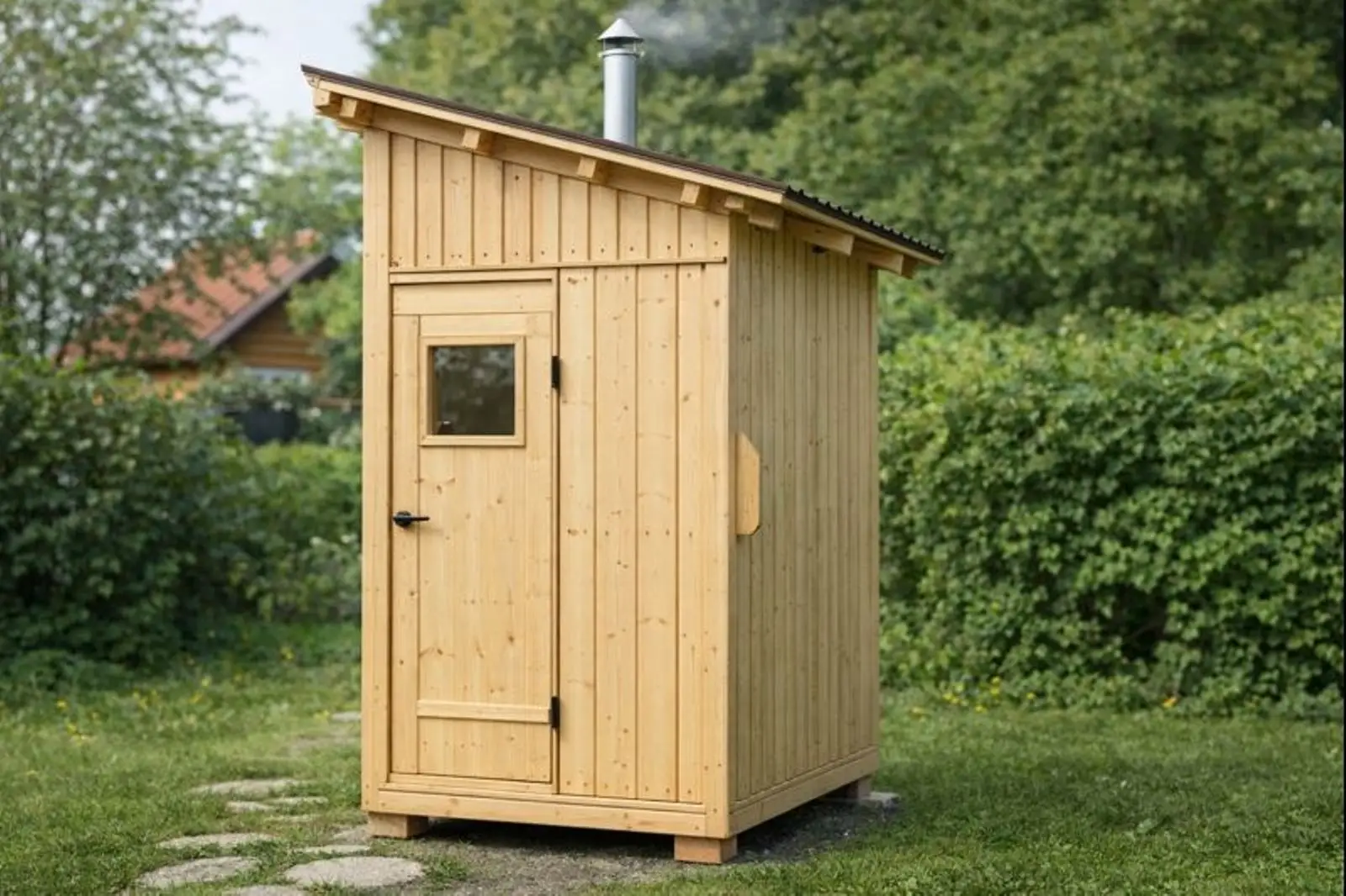
Many city dwellers would like to take a steam bath in their own sauna, but in most cases they don’t have such an opportunity. Even owners of dacha and garden plots don’t always have the conditions to build a full-fledged bathhouse: one lacks space, another lacks funds, a third lacks both. I considered myself one of these “unfortunates” whose desires don’t match their possibilities, until I came across the book “How to Become a Farmer,” which described a compact sauna.
I took this idea as a guide to action and designed and built my own mini steam room. It’s designed for one person, and it doesn’t even have a changing room. And although it’s a bit cramped compared to a regular bathhouse, the steam room performs its direct functions excellently. Another advantage is that the structure is collapsible and can be transported even in a passenger car trailer.
In appearance, the sauna-steam room is more like a shower cabin. Its overall dimensions are: length x width x height — 1600x1200x2400 mm.
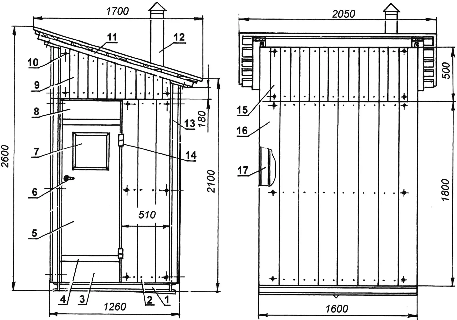
1 — frame (steel channel No. 8); 2 — partial side panel; 3 — threshold; 4 — strip (2 pcs.); 5 — door; 6 — door handle; 7 — window; 8 — lintel; 9 — upper side panel (2 pcs.); 10 — stud M10 (38 pcs.); 11 — roof panel; 12 — stove pipe; 13 — upper rear panel; 14 — door hinge (2 pcs.); 15 — upper front panel; 16 — main panel (2 pcs.); 17 — full side panel
The structure is foundationless (mounted on site on 6 bricks: 4 pieces are installed at the corners and two — in the middle of the length — near the drain gutter), and therefore a rigid and strong base frame is necessary. The frame (beams and crossbars) is made of steel channel No. 8 (with 40 mm flanges and an 80 mm high web) in the form of a rectangle with sides of 1200 and 1600 mm.
A water drain gutter made of 75×75 mm steel angle is installed in the middle of the frame. The gutter has a slope, so one end is welded to the frame beam flush with its top, and the other drops about 15 mm below the lower flange of the channel, forming a triangular opening with an area of 2.5 — 3 cm3 for water drainage.
The gutter conditionally divides the sauna into two halves. On part of one of the halves (to the right of the door), a horizontal platform made of 4-mm steel sheet is installed, on which a cylindrical steel stove is placed, oriented with its doors toward the center of the sauna.
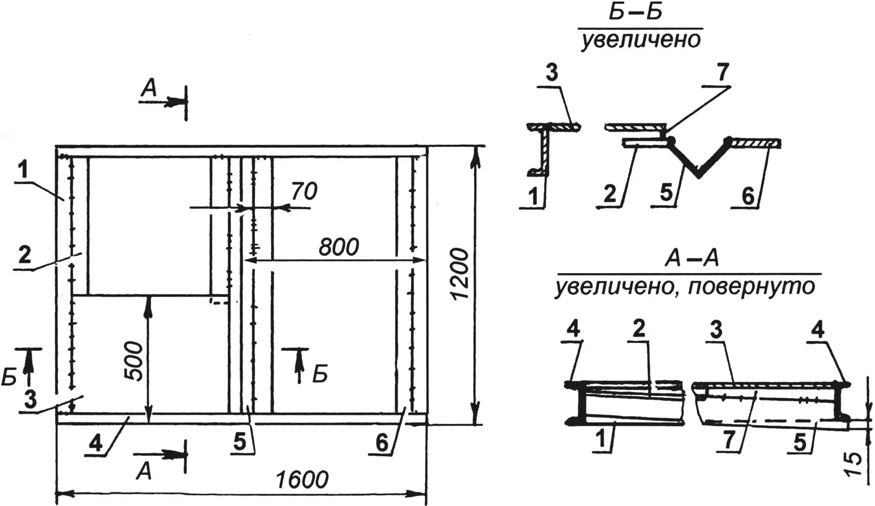
1 — cross beam (channel No. 8, L1120, 2 pcs.); 2 — short floor support (steel strip 70×50, L660, 2 pcs.); 3 — stove platform (steel sheet s4); 4 — longitudinal beam (channel No. 8, L1600, 2 pcs.); 5 — gutter (angle 75×75, L1160); 6 — long floor support (steel strip 70×5, L1120, 2 pcs.); 7 — wedge insert to cover gap (2 pcs.)
Steel strips 70 mm wide made of 5-mm sheet are welded to the edges of the gutter and crossbars of the frame from their inner side flush with the upper edges — they serve as supports for the floor boards. Since the strips on the frame are welded horizontally, and the drain angle goes with a slope, the floor has a double slope: from the sides — toward the center and from the front wall — toward the rear.
Because of this, wedge-shaped gaps remain between the horizontal platform under the stove and the floor at the entrance, as well as between it and the drain angle… Steel strips must be cut to the shape of the gaps and used to cover the gaps, welding the strips to the edges of the platform. The boards are fastened to the plates with nails — for this, holes are drilled in the latter with a diameter 0.1 — 0.2 mm smaller than the nail. The nails are bent from below. Floor boards should preferably be at air humidity (more than 25%).
The wall structure of the sauna is frame-panel. The frame consists of two half-frames. The posts of each — tall and short — are connected to each other only by crossbars with braces (without lower and upper frames).
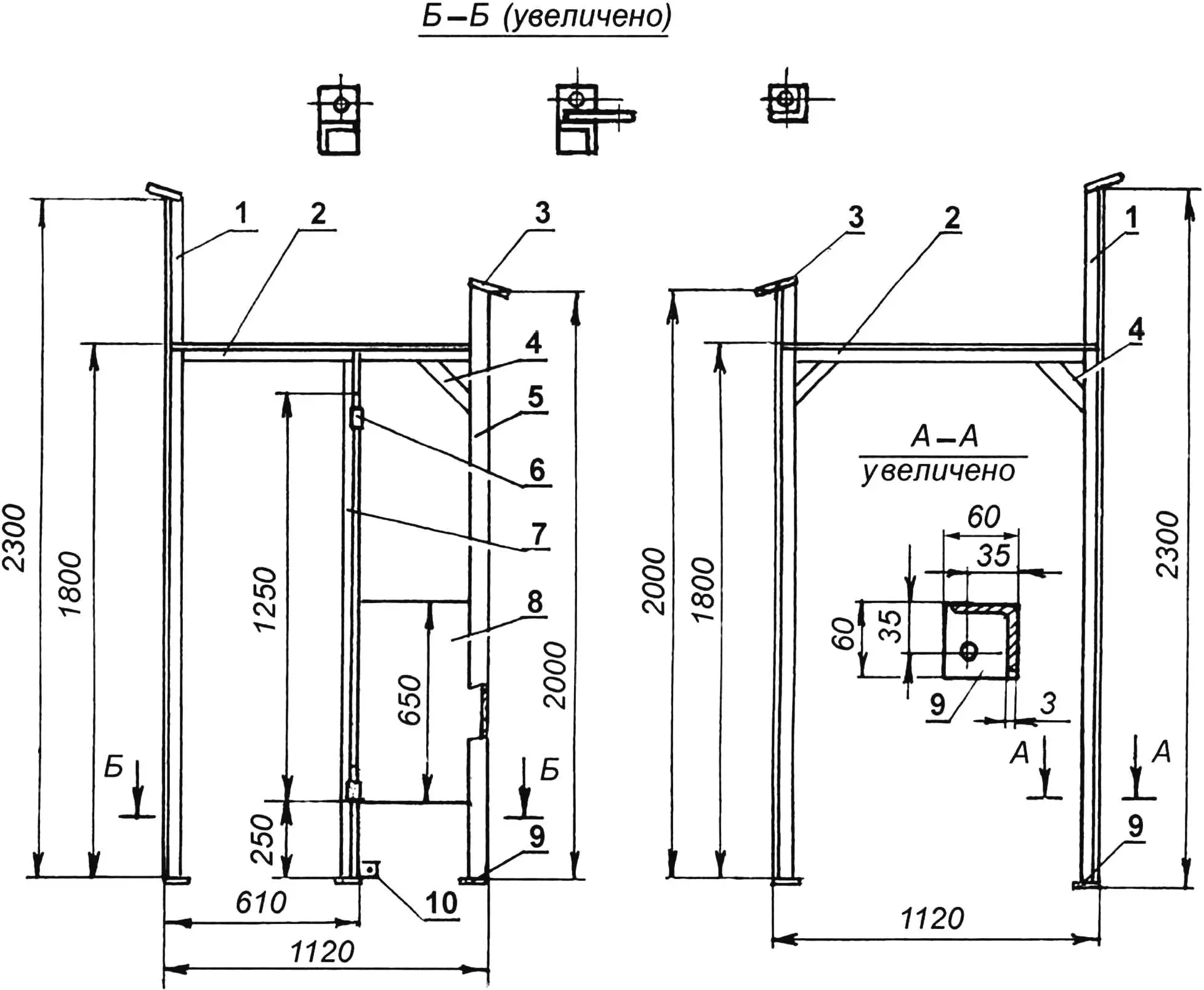
1 — tall posts; 2 — crossbars; 3 — brackets (steel sheet s5, 4 pcs.); 4 — gussets (steel strip 60×4, 3 pcs.); 5 — short post (2 pcs.); 6 — door hinge (2 pcs.); 7 — door jamb post; 8 — reinforcing plate (steel sheet s3); 9 — base plates (steel sheet s5, 5 pcs.); 10 — additional bracket for mounting partial side wall panel
Another short additional post — a door jamb — is welded into one of the half-frames. The height of the jamb is up to the crossbar, so the latter also serves as a lintel. The role of the second jamb is performed by the corner tall post. Half-hinges of the door’s hanging hinges are attached to the short jamb post with M6 bolts.
Steel plates 5 mm thick are welded to the lower and upper ends of the corner posts: at the bottom — square (50×50) base plates; at the top — inclined (at the roof slope angle) brackets. The posts are fastened to the base through corresponding holes with M8 bolts by means of the base plates. A single-pitch roof is attached to the brackets.
The wall panels are multi-layered. The basis of the panel is a frame made of boards and bars 40 mm thick: posts are made from 140 mm wide boards, and frames (lower and upper) and a lintel are made from 45 mm wide bars. The lintel is shallowly cut into the posts, and the frame bars and posts are simply butted at a 90° angle. All frame parts are nailed together with “one-twenty” nails, and holes with a diameter 1 mm smaller than the nails were pre-drilled in the bars. Nails were driven into the lintel at an angle of about 45°.
The inner side of the panel frame is first covered with packaging cardboard, then with polyethylene film and sheathed with vertically positioned quarter-grooved planed 15-mm boards (clapboard) made of hardwood.
Then the panel is turned over and the frame gaps are filled with foam plastic and foam plastic chips with a slight (2 — 3 mm) excess of insulation level over the frame elements. After this, the frame is sheathed on the outside with the same clapboard (but can be made of softwood), positioned vertically. The gable (upper) panels, both rectangular and triangular, are made using the same technology and the same design.
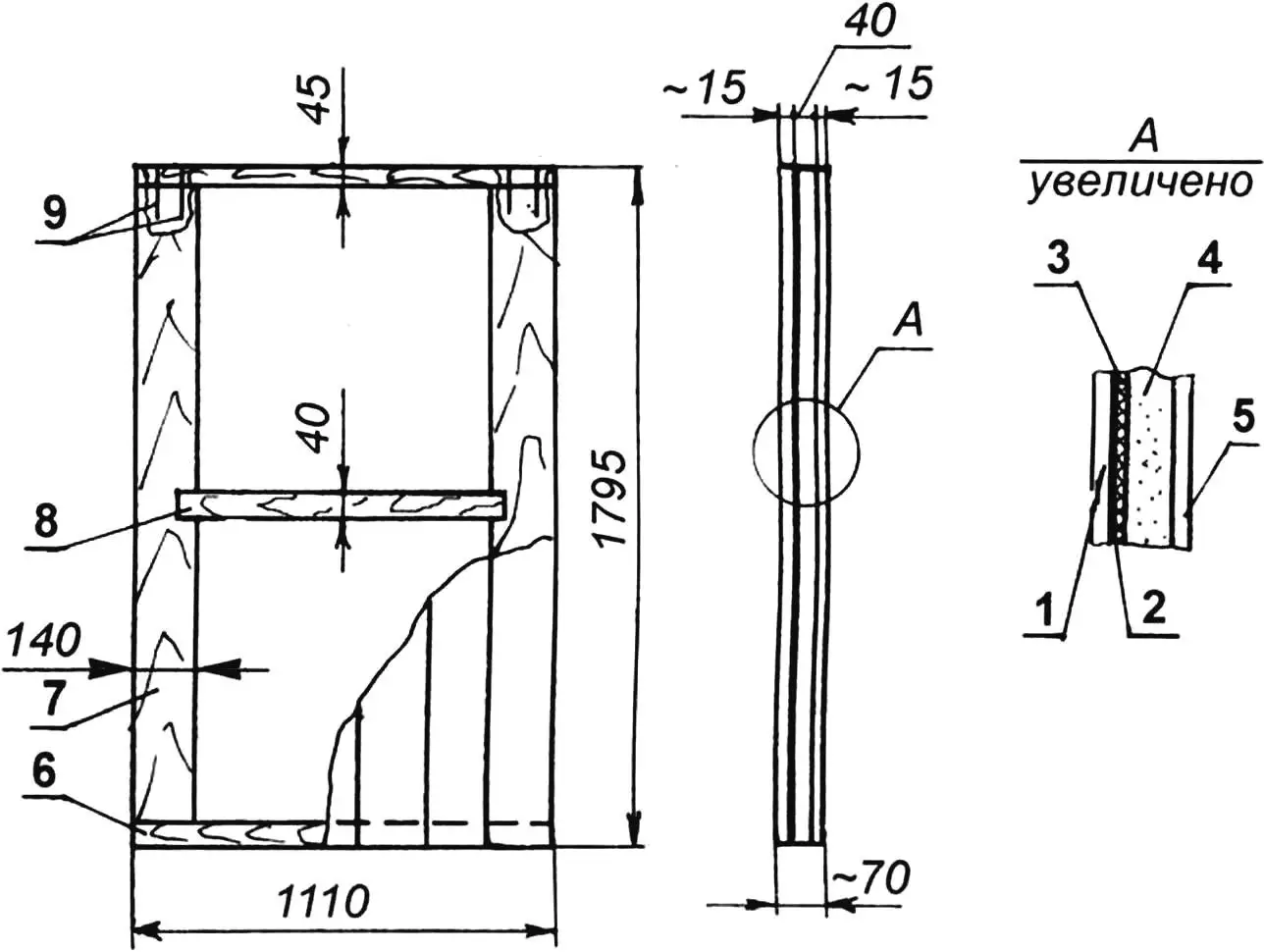
1 — inner sheathing (clapboard s15); 2 — polyethylene film; 3 — packaging cardboard; 4 — insulation (construction foam, s40); 5 — outer sheathing (clapboard s15); 6 — frame frame (bar 45×40, 2 pcs.); 7 — frame post (board 140×40, 2 pcs.); 8 — lintel (bar 45×40); 9 — nails L200 (as needed)
The wall panels are fastened to the half-frame posts (angles) with M8 tie studs 150 mm long with washers 30 mm in diameter. For this, corresponding holes are drilled in place in the panels and half-frame posts. And one more thing. To prevent gaps in the walls, strips of felt are nailed to the contacting surfaces when joining.
The roof and ceiling of the sauna are combined. The ceiling construction is the same as that of the wall panels, only without the outer clapboard sheathing. Instead, a lath made of “twenty” board with small overhangs on all sides is nailed on top, and a soft roofing felt roof is laid on it.
A standard apartment door, faced with hardboard (fiberboard), is used — many people simply throw these away now. The door is fitted in place, a window 350×200 mm in size is cut in it and glazed in two layers so it doesn’t fog up. The upper and lower parts (up to the hinges) are cut off from the door. A threshold and lintel are made from them respectively. The edges of the inner side of the door are upholstered with strips of felt.
A bench is installed at the “blind” (without door) side wall — on bars nailed at a height of 800 mm, a “forty” board 400 mm wide is laid against the front and rear walls. A step 430 mm high is installed near the bench, which can also be used as a seat.
To prevent accidental contact with the stove, a wooden lattice movable fence 1.5 m high and 1 m wide is made.
Since the stove stands only 250 mm from the wall, as a fire safety measure, part of the rear wall panel behind the stove is covered with roofing iron. In the side wall, this function is performed by the reinforcing plate.
The sauna stove is made like a column type. The main part of the stove — the firebox — is ready-made. It is made of thick-walled (10 mm) steel pipe with an outer diameter of 340 mm. The bottom and lid of the firebox are made of 15-mm steel plate. To increase the heat output of the exiting hot gases, a cylindrical expander 215 mm in diameter and 450 mm high is mounted above the firebox. It is made from a pipe with a wall thickness of 6 mm and welded on both sides with flanges of the same thickness.
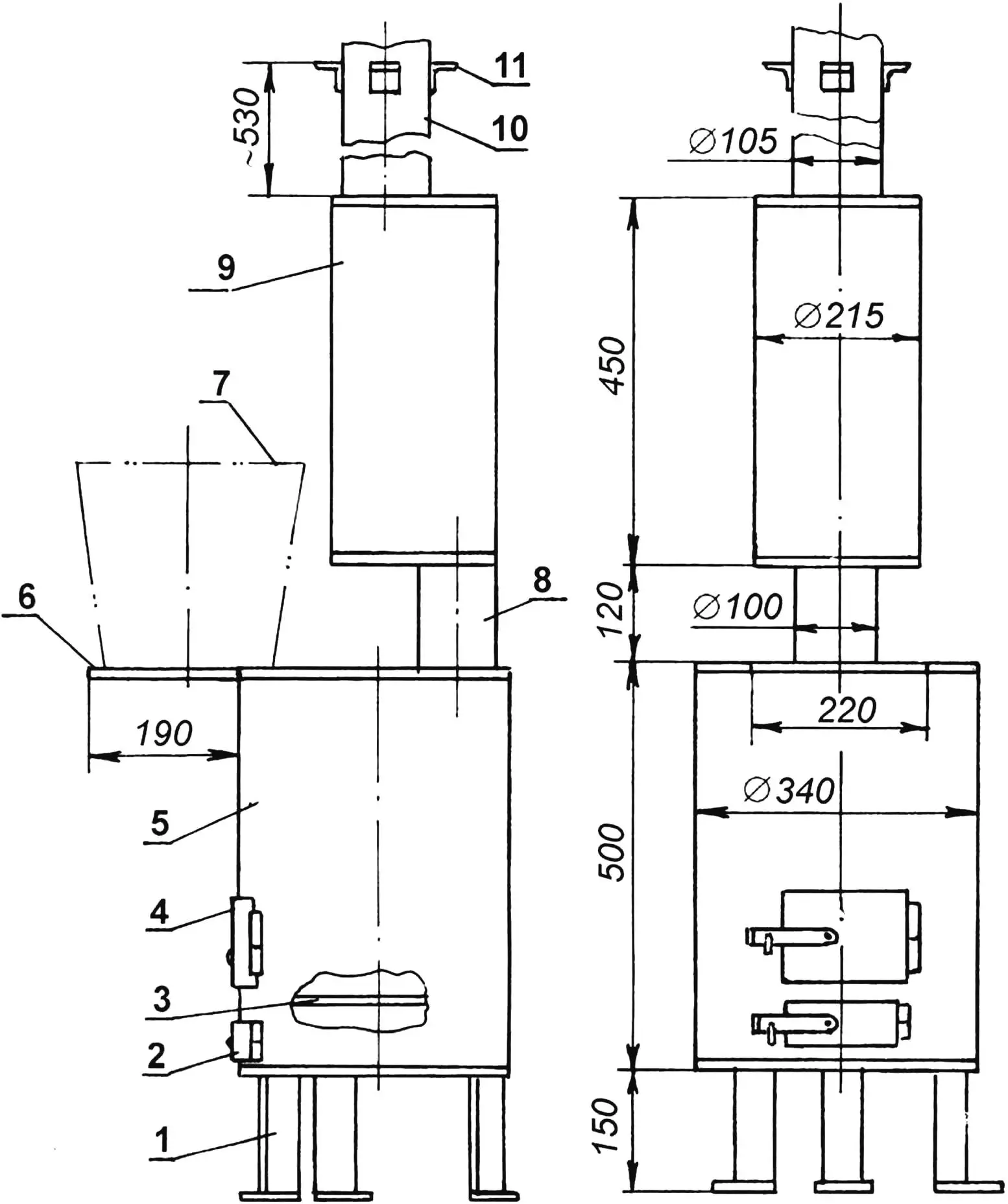
1 — leg (angle 63×63, 3 pcs.); 2 — ash pan door; 3 — grate (steel sheet s10); 4 — firebox door; 5 — firebox body (steel pipe 340×10); 6 — platform for water container (steel sheet s8); 7 — hot water container (bucket); 8 — sleeve (pipe 100×6.5); 9 — expander (pipe 215×6); 10 — chimney (pipe 105×4); 11 — brackets for sand box (angle 35×35, 4 pcs.)
The expander is connected to the firebox by a vertical sleeve — a section of round pipe 100×87 mm in diameter and 120 mm long. The sleeve is offset from the center toward the expander wall and firebox shell (in the opposite direction from the doors). The lower end of the chimney is welded into the upper flange of the expander, and it is also offset from the center toward the expander wall, but only in the diametrically opposite direction from the sleeve. The pipe itself has an inner diameter of 97 mm, and its wall thickness is 4 mm. The length of the chimney is such that it rises above the roof by at least 0.5 m. The upper end of the pipe is covered with a cap so that stray sparks don’t fly far, and rainwater doesn’t get into the firebox through the pipe.
A fire safety box with sand, made of 3 mm thick steel sheet, is installed on the chimney at the height of the crossbar. The dimensions of its bottom are 700×600 mm with 40 mm high flanges. The hole for the pipe in the bottom is cut in place. With one edge, the box rests on the crossbar of the frame half-frame and is fastened to it with two M6 bolts through corresponding simultaneously drilled in-place holes in both parts. To hold the box on the pipe, four brackets made of 35×35 mm angle are welded to it. Thus, the box serves as a console that holds the chimney (and together with it the expander) in a vertical position.
The firebox grate is made of 10-mm steel plate with longitudinal parallel slots 10 mm wide with a pitch of 20 mm. The grate, like the box, rests on three brackets made of 35×35 m angle, welded inside to the firebox walls.
A small console platform made of 8-mm steel sheet is also welded in continuation of the firebox lid. A bucket with preheated water is placed on it — so it doesn’t cool down.
If no other heat source besides the sauna stove is expected, then to heat water, an additional container with a tap will have to be made on the firebox lid. The stove on the platform is installed on three legs made of angle No. 6.3. Support plates with holes are welded to the angles from below, through which the legs are fastened to the platform plate with M6 bolts.
In practice, it turned out that the ash pan door is not really needed.
The sauna stove design is, of course, not ideal, but I proceeded from what I had available.
To heat the sauna well, about 4 kg of firewood is required in summer. Firewood is prepared in the form of thin logs no more than 300 mm long. You can steam already about fifteen minutes after starting the fire.
The choice of location for the sauna must be approached responsibly. First, take into account the prevailing wind direction — so that on the leeward side, in the zone reachable by flying sparks, there are no flammable objects. Second — ensuring drainage or filtration of used water into the ground.
«Modelist-Konstruktor» No. 7’2005, P. KOPYEV
Recommend to read
 Suzuki JIMNY
Their first SUV called the JIMNY Japanese company Suzuki has released in 1968. Utilitarian and inexpensive all-terrain vehicle was used in Japan, good demand, and the company began to...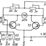 A simple voltmeter
measuring constant voltage value of 100 V. It is produced by the bridge circuit for the transistors T1 and T2. In one diagonal bridge included a measuring device in the other power...
