I am a long-time, or rather, hereditary subscriber to the magazine “Modelist-Konstruktor”. At first (since 1972), my father – Galkin Grigory Petrovich (he is now 80 years old) – subscribed to the magazine, and then I did myself. Since the beginning of the “Aviatscollection” supplement, I have been subscribing to it as well.
As long as I can remember, we always had automotive and motorcycle equipment in our yard. The love for it was passed down from my father to both my brother and me. And in my youth, I also became interested in aviation. Under the influence of the magazine, I chose my profession: I graduated from the Vyborg Technical School and received the specialty of an aircraft mechanic. I worked for 21 years with 7,000 flight hours as a flight engineer on a Mi-8 helicopter in the Far North regions.
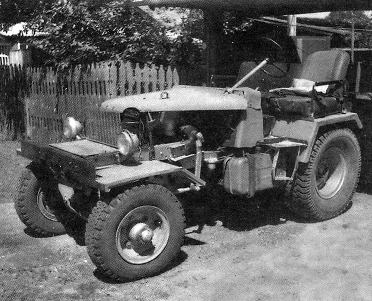
In the late 1990s, my father retired (although he worked for another 7-8 years at the request of management – he was an excellent crane operator). At the same time, he built a tractor, which I present to the readers of “M-K”.
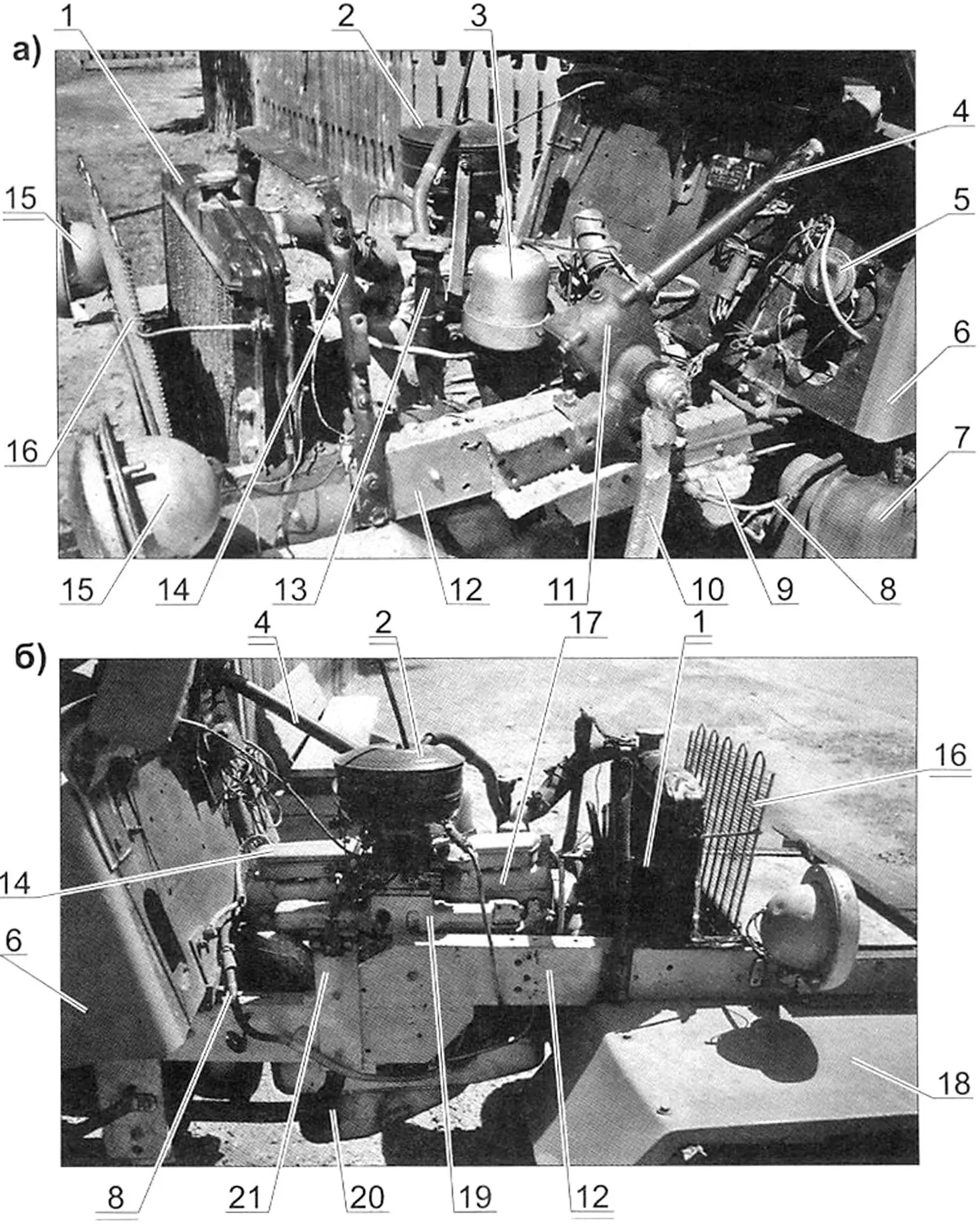
1 — radiator (from GAZ-52 truck); 2 — air filter; 3 — oil centrifuge; 4 — steering shaft (from GAZ-52 truck); 5 — horn (from VAZ car); 6 — front shield; 7 — fuel tank (V=57 l.); 8 — fuel line; 9 — fuel filter; 10 — steering arm (extended); 11 — steering gearbox (from GAZ-52 truck); 12 — frame; 13 — engine oil filler neck; 14 — hood holder bracket; 15 — headlight (2 pcs.); 16 — radiator protective grille; 17 — engine (from GAZ-52 truck); 18 — front fender (2 pcs.); 19 — engine intake manifold; 20 — oil pan; 21 — cable wiring bracket
The construction of the tractor began with an old Bulgarian loader that my father bought from one of the downsizing military units. However, only the four-cylinder diesel engine, the front drive (pulling) axle, and some secondary units and components were useful from it – for example, the fuel tank, instrument panel. And if the engine was incomplete (without injectors) and quite worn out, the axle turned out to be a real find: with wheel planetary reducers and differential lock. On the tractor, it became a drive (but pushing) rear axle.
The injectors and other fuel equipment for the engine were adapted from the T-40 skidder tractor (later replaced them with equipment from a Swedish log truck, which fit almost without modifications).
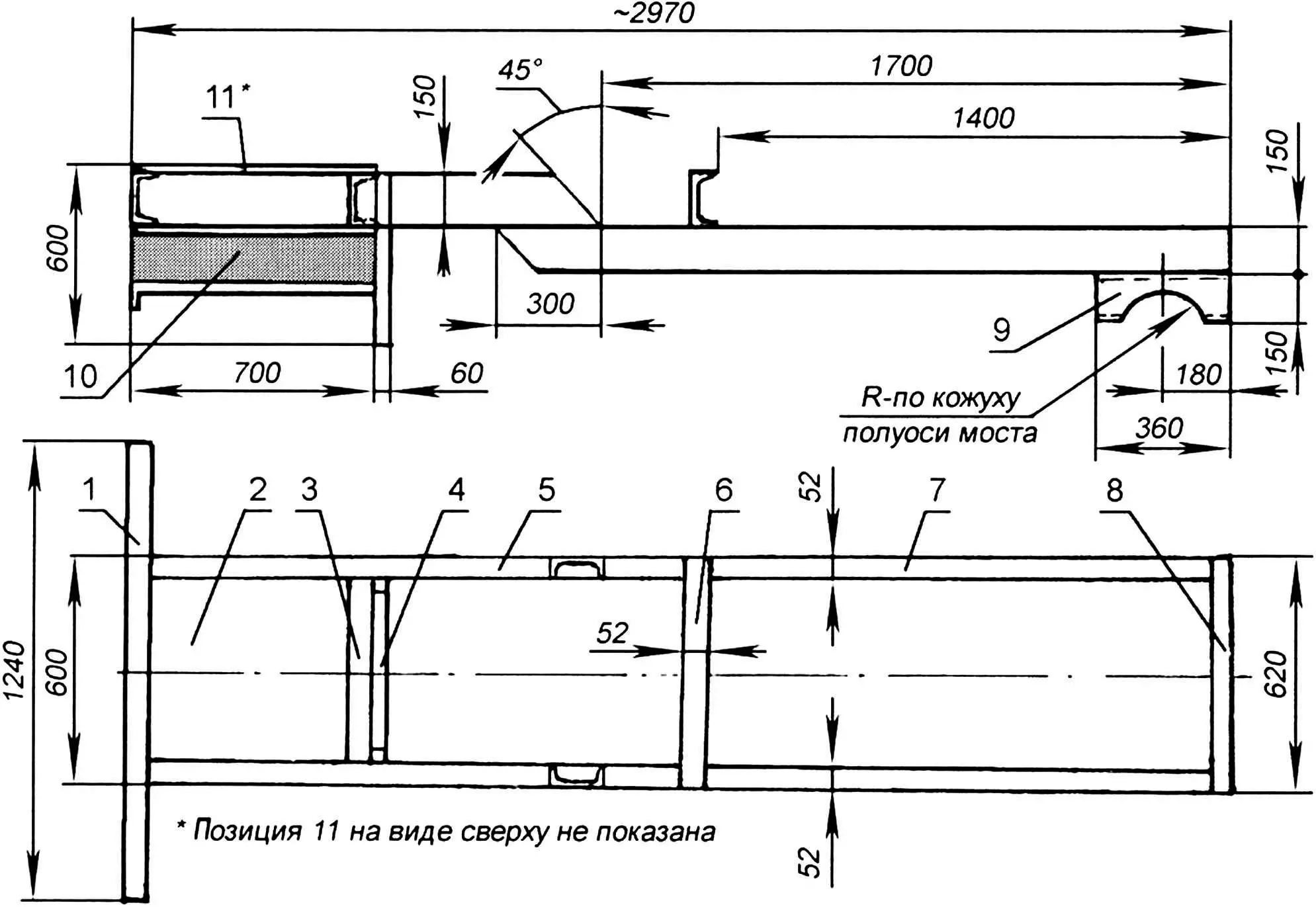
1 — front crossmember (channel No. 12); 2 — middle platform (steel sheet s4); 3 — front crossmember (channel No. 12); 4 — front engine support mounting bracket (U-shaped profile from steel sheet s4); 5 — front part of side member; 6 — central crossmember (channel No. 12); 7 — rear part of side member (channel No. 12, 2 pcs.); 8 — rear crossmember (channel No. 12); 9 — rear axle cradle (channel No. 12, 2 pcs.); 10 — spacer (channel No. 12, 2 pcs.); 11 — upper platform (steel sheet s4)
The tractor frame is welded, relatively simple – has a slightly trapezoidal shape in plan – slightly wider at the rear relative to the front. It was welded on a level floor. The frame consists of a pair of side members and several crossmembers. The side members are made of channel No. 15 with dimensions (flange x wall height x wall thickness) 52x150x4.8 mm with a step (lowering) in the middle part – so that the contact patches of tires of different front and rear wheels are at the same level when the frame is horizontal. The step area is welded with an overlap and reinforced with gussets and overlays. The crossmembers are made of channel No. 12 with dimensions (flange width x wall height x wall thickness) 52x120x4.8 mm. At the same time, the front and rear crossmembers are also bumpers. Behind the front bumper, a 600 mm wide platform made of 5 mm steel sheet is welded from below. Two spacers made of channel No. 12, 700 mm long, also with a platform, are welded to the platform, to which the front axle pivot bushing is attached.
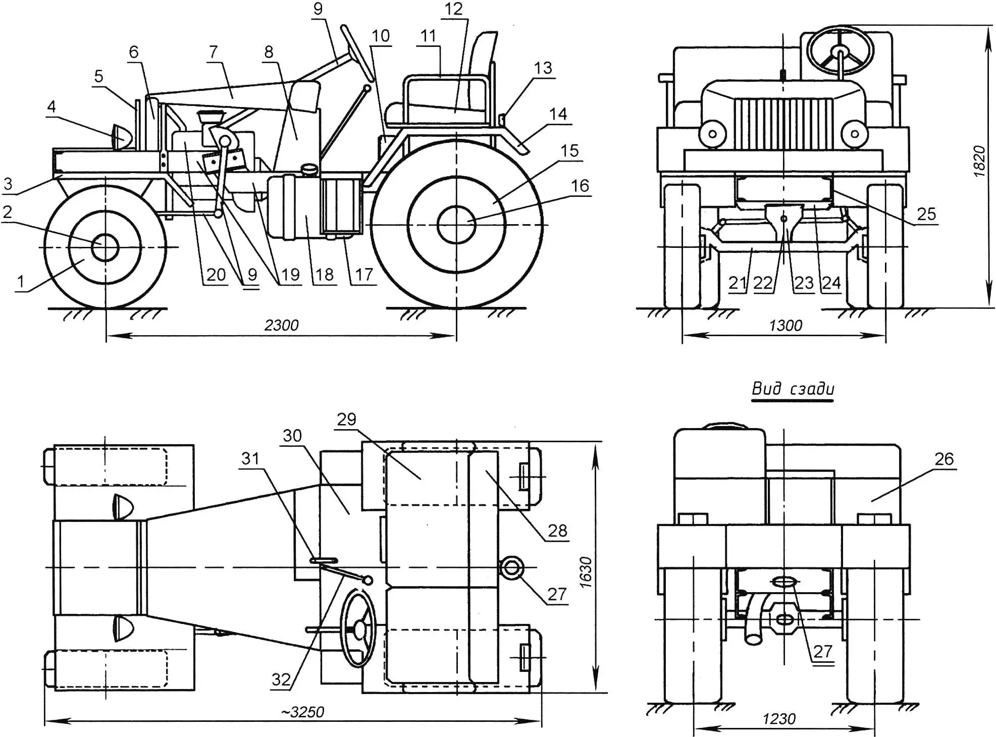
1 — front wheel (tire and rim — from UAZ-469 car, disc — from agricultural machinery); 2 — front wheel hub (from agricultural machinery, 2 pcs.); 3 — front fender (refrigerator panel, 2 pcs.); 4 — headlight (from ZIL-157 truck); 5 — radiator protective grille (refrigerator radiator); 6 — radiator (from GAZ-52 truck); 7 — hood (from GAZ-69 car); 8 — front shield (from loader); 9 — steering (from GAZ-52 truck); 10 — battery; 11 — armrest; 12 — driver’s seat; 13 — rear signal lights (from VAZ-2101); 14 — rear fender (refrigerator panel, 2 pcs.); 15 — rear wheel (tire and rim – from K-700 tractor cargo cart, disc from agricultural machinery, 2 pcs.); 16 — rear wheel hub (from agricultural machinery, 2 pcs.); 17 — step (2 pcs.); 18 — fuel tank; 19 — frame; 20 — engine; 21 — front axle beam (from GAZ-52 truck); 22 — axle pivot; 23 — axle beam suspension bracket to frame; 24 — support plate; 25 — spacer (2 pcs.); 26 — rear shield; 27 — tow hitch; 28 — passenger seat back; 29 — passenger seat; 30 — floor (steel sheet s4); 31 — parking brake handle; 32 — gear shift lever
Behind the side member steps, a crossmember of the same channel is welded to them, and a shield is welded to it. The tractor control pedals, steering shaft bracket, and from the engine compartment side – electrical units are attached to the shield.
Cradles for mounting the rear axle beam to the frame are welded to the rear ends of the side members, from below.
The front axle (together with the steering linkage and steering knuckles) was adapted from a GAZ-51 truck. It is attached to the frame on a central pivot, that is, the axle is oscillating. The front wheel hubs are from a T-40 tractor cargo cart, but the wheels and tires themselves are from a UAZ-469 car.
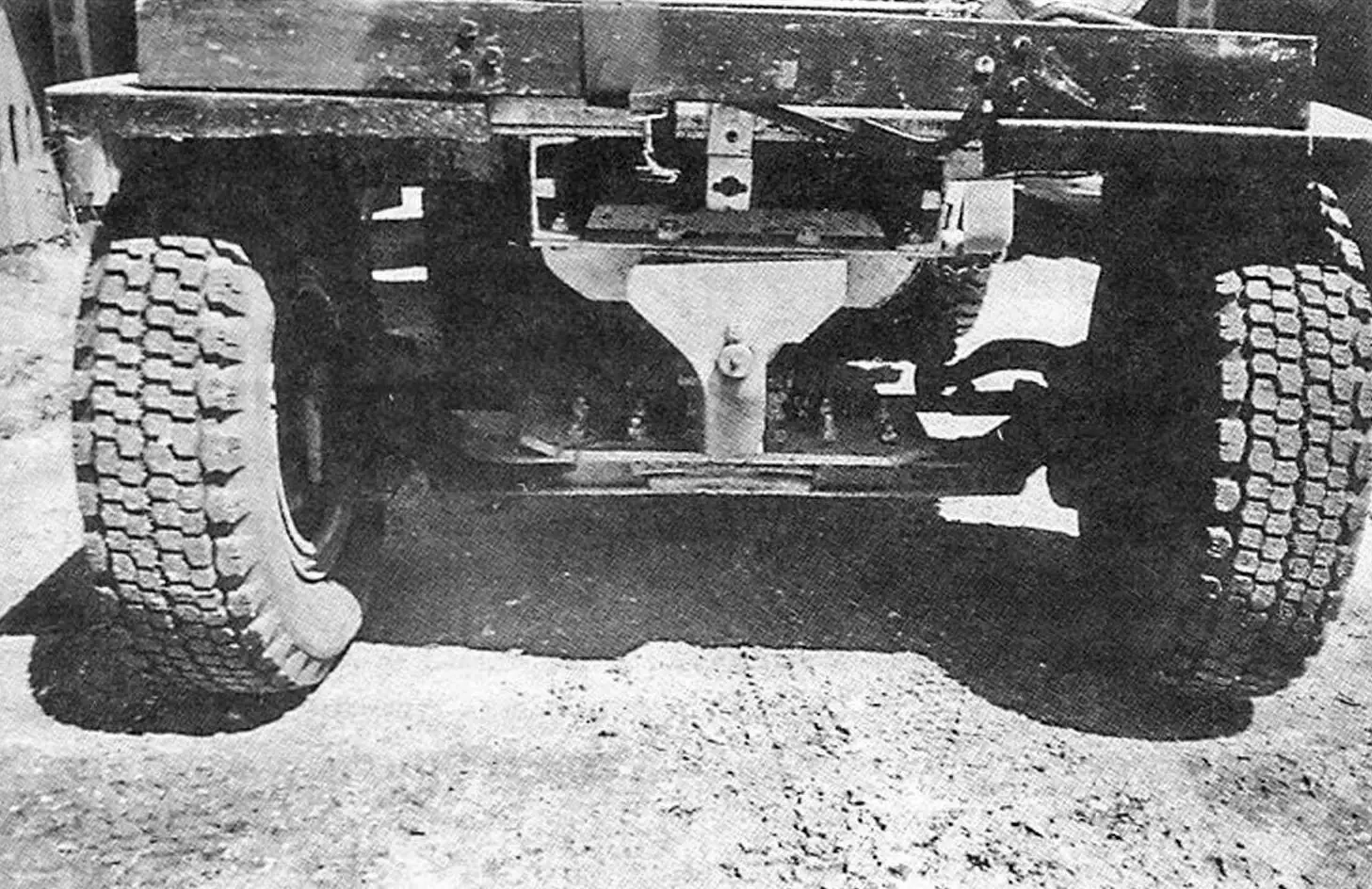
The rear axle is connected to the frame cradles through rubber pads and secured with U-bolts – a pair on each side. The tow hitch is welded directly to the axle – this is even more reliable than to the frame – after all, earlier, when the axle was on the loader, a lifting boom was attached to these brackets, and the axle itself carried all the loads.
The rear wheels are homemade. Their rim is from ZIL-157 car wheels, and the hub part (disc) is from loader wheels. The disc was cut out by electric welding and turned on a lathe. Then the disc was inserted into the rim, and after checking their mutual position, the parts were welded: from the inside with a continuous weld, and from the outside – with an intermittent one. The tires from ZIL-157 were replaced due to wear with identical tires, but from agricultural machinery.
In the transmission, the gearbox and clutch basket were used from a ZIL-130 truck. Further, the torque is transmitted to the drive axle by means of a double cardan shaft with two splined couplings.
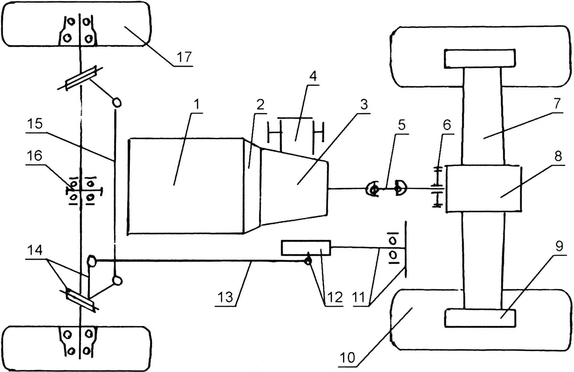
1 — engine; 2 — clutch basket; 3 — gearbox; 4 — power take-off reducer; 5 — double cardan shaft; 6 — disc brake; 7 — rear drive axle;
8 — final drive housing with self-locking differential; 9 — hub planetary reducer housing (2 pcs.); 10 — rear drive wheel (2 pcs.); 11 — steering wheel with steering shaft; 12 — worm reducer with arm; 13 — longitudinal tie rod; 14 — steering knuckle with lever (2 pcs.); 15 — transverse steering tie rod; 16 — front axle pivot axis; 17 — front steering wheel (2 pcs.)
The electrical equipment on the tractor is assembled, as they say, “from all over the world”: headlights – from ZIL-157, front “turn signals” – from GAZ-53, rear lights – from VAZ-2101. The engine is started by an electric starter from the ignition switch (there is also a kick starter, but as far as I remember, it was never used). The battery is 72 Ah, located under the passenger seat and closed in front with a lid on spring locks.
The engine compartment hood is from GAZ-69. The driver’s seat is from a K-700 tractor, but without suspension. The passenger seat is two-seater, homemade: its frame is made of 25×25 steel angle, base is made of thick plywood, padding is made of porous rubber, upholstery is leatherette.
After working on the tractor for about ten more years, the diesel from the loader “gave up the ghost”. Boring the cylinders and crankshaft journals helped only briefly. Everything came down to the lack of “native” spare parts, as they did not fit from other diesels. The question of replacing the engine arose.
At this time, once again, there was a reduction in the army, and a nearby repair battalion was being disbanded. Equipment was being sold off. That’s where I bought an engine from a BTR-60 with a capacity of 84 hp. with all equipment: shielded ignition wiring, starter, generator, carburetor, as well as a clutch basket and gearbox. This inline six-cylinder engine was also used on GAZ-52 trucks, so the missing equipment (for example, the liquid cooling system) was borrowed from it. When installing the engine, I had to redo the mounting unit to the frame. Now it is secured at the front on rubber pads in a U-shaped (inverted) suspension, and at the rear – on braces behind the gearbox housing. However, gear shifting became direct, whereas it was previously remote linkage.
The tractor brake is mechanical, disc. It is located on the tail of the final drive gear shaft (near the axle reducer). The brake drive is double: from the pedal through a rod and from the handle (located under the instrument panel) – using a cable.
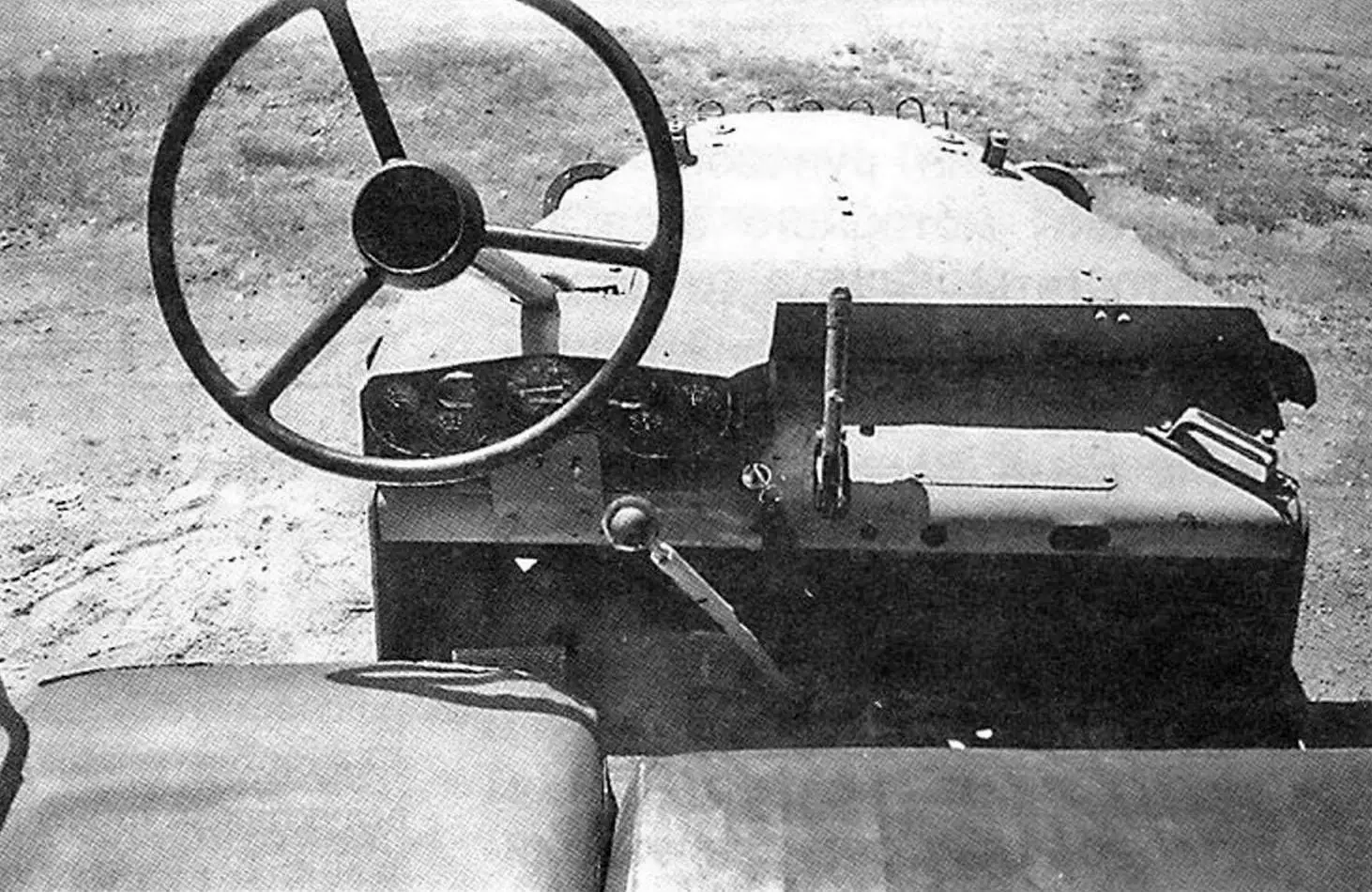
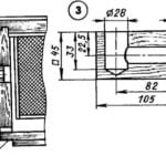
The steering mechanism (reducer, column, steering wheel) is from a GAZ-52 car. Only the steering arm was modified: extended with a welded suitable square steel rod. The tie rod going from the arm to the steering knuckle lever is homemade, tubular with ends.
The instrument panel is used from GAZ-52. It has an ammeter, coolant temperature gauge, oil pressure gauge, fuel level gauge, speedometer. A mechanical “ground” switch (toggle switch) is hidden under the instrument panel – it serves as an anti-theft device.
The tractor is made roughly, but reliably – operation for two decades both for transporting cargo and for land cultivation has proven this. The successful design of the tractor was largely due to the rear axle from the Bulgarian loader. It turned out to be reliable and perfectly handles providing the tractor with cross-country capability in difficult road conditions and traction in agricultural work. In case of wheel spin of one of the rear axle wheels during straight-line movement, it is instantly locked with the other. On turns, the hub planetary mechanisms begin to work in the axle, and when the steering wheel is turned to the stop, the tractor can turn around one wheel with the front end skidding. But this is already extreme, and it is undesirable to turn so sharply.
In terms of its capabilities, the loader axle even surpasses the axle from the GAZ-66 all-terrain truck, which, moreover, needs to be shortened (narrowed track) for the tractor.
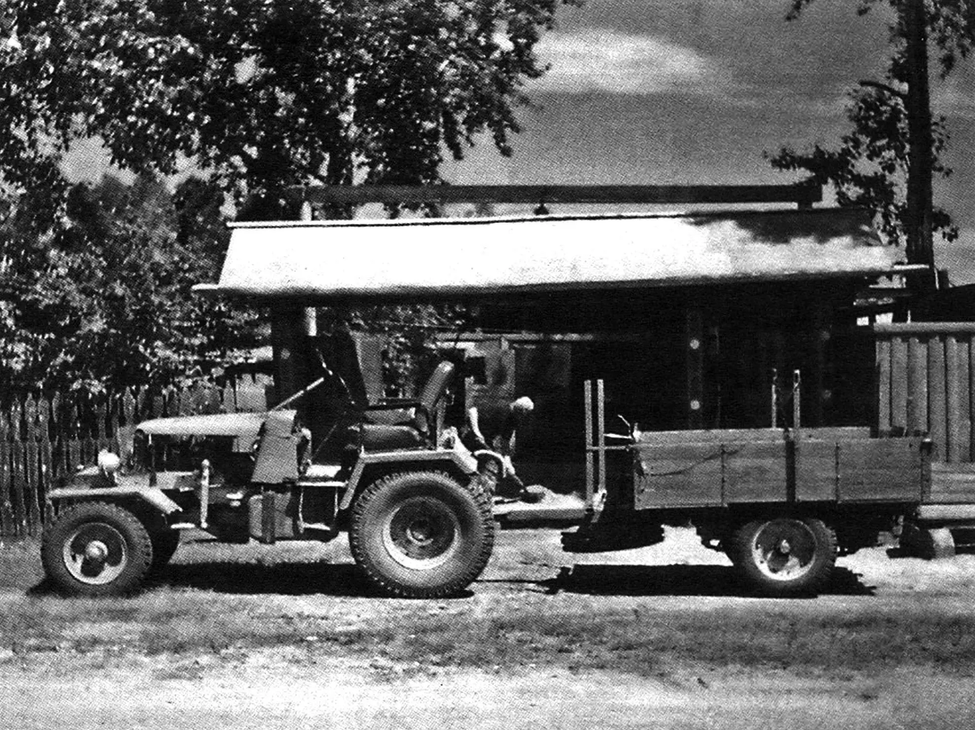
For transporting cargo, a homemade single-axle cart is also attached to the tractor. It is already the third one – from one to another the load capacity increased, and the designs were similar.
The cart frame is welded from the same channel as the tractor frame (No. 12). The axle and wheel hubs are from agricultural machinery, the suspension springs are from a GAZ-53 truck. The body frame is welded from 25×25 steel angle. The sheathing is made of tongue-and-groove “twenty” boards, attached to the frame with bolts. The front and rear sides of the cart are folding (held in horizontal position by chains), which allows transporting long loads.
«Modelist-Konstruktor» No. 9’2011, A. GALKIN
Recommend to read
 BEES WATERED AND FED THE MACHINE
When rented with option to purchase three of the apiary, I realized how difficult it is to handle a large number of bee colonies. Part of the problem was solved with the help of the...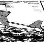 OVER THE WATER – FLYING BOAT
In the literature on model airplanes is not so much focus on radio-controlled models of seaplanes, although, in practice, many enthusiasts prefer them purely "land", considering the...
