The tank is a cylindrical container of circular or rectangular shape in cross section. Its volume depends on the needs of the area the beds of irrigation.
The sides and bottom of the tank can be metal or plastic.
To the upper edge of the tank is welded axially to the number of pins which are provided with springs 13 and the roof 12. On the tank set all the controls of the device.
Fig. 1. A schematic structural diagram of the device “Automatic watering”:
1 – tank; 2 – bucket; 3 – siphon; 4 – the adjusting valve; 5 – pipeline; 6 – reservoir; 7 – drain valve; 8 – stand; 9 – rain valve; 10 – lever; 11 – a pusher; 12 – the fuel tank cap; 13 – spring; 14 – a glass; 15 – valve
Fig. 2. The scoop:
1 – side wall with holes for passage of the shaft serving as the axis around which rotates freely bucket; 2 – balance weight
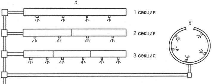
Fig.3. Distribution network:
a – direct polnye pipe; b – circular irrigation pipes.
Fig. 4. Rain flap:
1 – housing; 2 – rubber gasket; 3 – rod; 4 – lever; 5 – pusher; 6 – pin; 7 – plastic cover; 8 – fitting for water drainage
Fig. 5. Emergency valve:
1 – housing; 2 – nut; 3,8 – rubber gasket; 4 – the wall of the tank; 5 – a ball; 6,11 – spring; 7 – rod; 9 – longitudinal groove; 10 – annular groove; 12 – fitting; 13 – direction of water
The bottom and rear wall of the bucket (Fig.2) are rectangular. The side walls are triangles with holes 1 for passage of the shaft serving as the axis around which rotates freely bucket. To the rear is attached the adjusting the load 2. The position of the axes and the center of gravity of the bucket are selected in such a way that the hypotenuse of the triangle held in a horizontal position during its filling with water. The bucket tips over after filling and returns to its original state after emptying.
The volume of the bucket is determined from the condition of sufficiency of water in it to charge and start the siphon.
The siphon 3 (Fig.1) is an arc-shaped upright rigid tube, one end of which is open to receive water from the tank and the other connected to the water distribution pipeline network. The height of the siphon determines the amount of water needed for watering plants. When the water flowing into the tank from the water supply system, reaches the top level of the siphon, it runs through the last portions of water from the bucket and the water begins to flow into the distribution network. The siphon works as long as the water level in the tank reaches its open end.
The volumetric rate of flow of water coming from the water supply network to the tank is regulated using a ball or gate valve 4 (Fig.1). Ultimately, this faucet is designed to establish the required frequency of watering.
Distribution network (Fig.H) consists of a set of irrigation pipe with holes for water spraying and hose. Irrigation pipe can have a rectangular and annular shape. Straight pipes used for watering plants planted linearly (a). Pipes can have different lengths by joining the individual sections. The distance between the nozzles are selected with the step of planting. This pipe can be made with an excess number of nozzles, some of which must be closed with plugs taking into account the biological requirements.
Annular irrigation pipe used for watering large trees and shrubs (b).
In the subsystem termination and restoration of irrigation after rain (Fig.1) storm valve 9, the lever 10, the pusher 11, the tank cover 12 and spring 13.
Tank cover 12 made in the form of a tray with a recess for collecting rainwater, which serves as a load for closing the valve 9. On the periphery of the cap is drilled a number of axially spaced holes for planting it on the pins welded to the upper edge of the tank. The depth of cover shall be designed so that the weight accumulated in her rainwater was sufficient to close the valve 9, but after the cessation of rains the moisture should evaporate in less than a day, so that under the action of springs 13, the valve 9 again opened.
The pusher 11 is attached to the top end to the top of the tank, and the lower end to the lever 10. The pusher also sits the Cup 14 (Fig.1) an emergency subsystem.
Rain the valve (Fig.4) is constructed by analogy with float plumbing the toilet tank. General view of the rainfall of the valve shown in Fig.4. It consists of a housing 1, rubber strip 2, rod 3, lever 4, a pusher 5, stud 6, the plastic cap 7 and the fitting 8.
Rain valve differs from the known ball valve is the fact that it is driven by different forces. Float valve use buoyant force and the weight of the float, and in the rain -the weight of rain water and the elastic force of the springs.
Alarm subsystem (Fig.1) includes a Cup 14 and drain valve 15.
The insert 14 serves to set the water from the tank in case of overflow, when the water level rises to the level of the upper edge of the glass. The weight of the accumulated water should be sufficient to close the rain flap 9 (Fig.1), stopping the access of water into the tank.
The emergency valve 15 (Fig. 1) attached at the bottom of the tank and is used for automatic emptying of the tank to the distribution system in the event of an accident, i.e., if the siphon will not start.
The valve design is shown in Fig.5. The valve opens under the water pressure when its level exceeds the height of the wall of the Cup 14 (Fig.1). The stress in the rod 7 (Fig.5) under the set pressure is set using the fitting 12 and spring 11. When the pressure exceeds a predetermined limit, the rod 7 moves to the left. As soon as the ball retainer moves to the annular grooves 10, the balls 5, under the action of the spring 6 fall into this groove and lock the rod, opening the water path through the valve in the distribution network (water flow shown by arrows).
LITERATURE
1. Konstantinov A. R., Evaporation in nature, in 1968.
2. Hydraulics, water supply and Sewerage, 1980.
3. Archers B. V. 1000 practical advice for gardeners and vegetable growers, 1997.
4. Repin H. H. Sanitary-technical devices, 1975.
5. Patent No. 2333632.
G. DAVLETSHIN, candidate of technical Sciences
Recommend to read HONDA S2000 Scale model 1:18. Honda S2000 — the car rear-wheel drive front-engined and rear wheel drive Roadster with equal weight distribution on front and rear axle, manufactured by Honda.... CHILDREN’S TWO FLOORS If you are on a family Council have decided to allocate the child in the new apartment though the smallest in area, but still separate room, then take the time to make it familiar to an...

 The device of “Automatic” is intended for irrigation of vegetable and fruit plants to individual garden plots. Watering is carried out automatically at specified intervals (e.g., daily). For normal operation of the device requires the Central water system of cooperative gardening.