It’s hard to imagine urban and rural life without running water nowadays. Well, if there’s no centralized water supply and a well is nearby, the simplest solution is to use an electric pump to lift water. However, that’s only half the job. A home water supply system should include a storage tank, automatic pump control elements, and a distribution network. That’s why engineering solutions here can be very diverse. Our readers share some of them today.
WATER PRESSURE… BATHTUB
The installation of a traditional scheme with an upper pressure tank (see fig.) is most conveniently placed in the attic of a country house. Choose a large tank—about 200 liters—preferably made of stainless steel or duralumin. An ordinary barrel must be thoroughly coated inside with waterproof paint to prevent corrosion. I used an enameled bathtub as a water pressure tank. Although it’s quite heavy, it has a solid volume, doesn’t rust, and its outlet and overflow holes are convenient for connecting to the system.
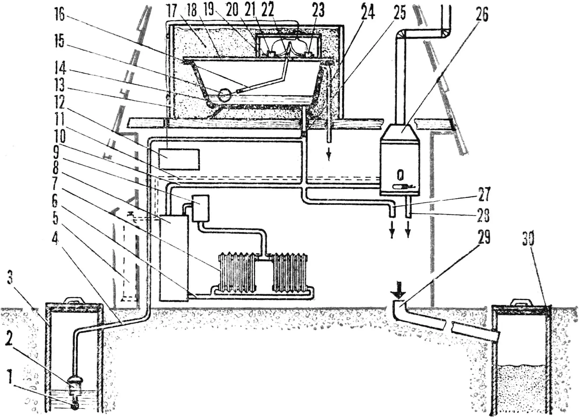
Scheme for equipping a country house with an autonomous water supply:
1 — water intake with filter, 2 — electric pump, 3 — well, 4 — supply pipe, 5 — gas cylinder, 6 — return pipe of water heating system, 7 — radiator, 8 — gas water heater, 9 — expansion tank, 10 — feed pipe, 11 — gas pipe, 12 — pump control unit, 13 — box, 14 — pressure tank (bathtub), 15 — float, 16 — lever, 17 — thermal insulation material, 18 — top cover, 19 — control elements compartment, 20 — control rod with flag, 21 — upper level sensor, 22 — lever pivot axis, 23 — lower level sensor, 24 — overflow pipe, 25 — solenoid valve, 26 — gas column, 27 — to cold water consumers, 28 — to hot water consumers, 29 — sewer pipe, 30 — drain well.
To operate the home water supply year-round, the tank will need to be insulated. Enclose it in a wooden box and fill the gaps between its walls and the bathtub with insulation—sawdust, slag, expanded clay. The bathtub should be covered with a wooden lid on top, and a box for automatic control elements—level sensors—should be installed on it.
To automatically maintain a constant water level in the tank, equip the bathtub with a regulating float device. Its design can be very diverse and depends mainly on the switches used. Non-contact switches are considered the most reliable, so I used two BVK-type switches. A lever with a float at the lower end is hinged in the lid brackets and, when the level in the tank changes, moves control rods with aluminum flags—glued foil strips—with its upper arm. The lever dimensions and sensor positions are chosen so that they activate at the minimum and maximum water levels in the tank.
A country house with such a water supply should also be supplemented with a sewer system. For this, dig a pit 1.5—2 m deep in the yard 10—15 m from the house and concrete or brick its walls. It’s even simpler to use a section of steel or concrete pipe Ø 700—1000 mm for this purpose. Sewer pipes for draining used water should have Ø 100—150 mm. They should be laid in the ground at a depth of at least 600—700 mm with a slight slope toward the collection well.
If your village has gas cylinder exchange or centralized gas supply, your water supply will provide the house with all the amenities of a city apartment. With gas water heaters like AGV-80, AGV-120—water heating, and with a gas column—hot water for household needs. The only addition to the water supply system in this case is the installation of a solenoid valve that closes the supply pipe from the pressure tank. It’s necessary so that water flows to the column directly from the pump. In this case, its pressure is higher than when supplied from the pressure tank, and the gas regulator valve will work reliably.
N. KHOREV, st. Doskino, Gorky Region
UNDER AIR PRESSURE
Installing a water pressure tank in the attic is perhaps the simplest solution, but it seemed insufficiently perfect to me. After all, to get good pressure, the tank must be raised quite high, and for normal operation in winter, complex thermal insulation is required. I decided to do it differently.
My water pressure tank made of stainless steel, with a capacity of about 60 liters, has only one outlet at the bottom. On top, it’s hermetically sealed with a textolite lid. The pump installed in the well supplies water from the intake with a check valve to the distribution system and in parallel—to the tank. Since the latter doesn’t communicate with the atmosphere, the air above the level gradually compresses and, acting as a pneumatic spring pushing water out of the tank, creates the necessary pressure. This scheme allowed placing the pressure tank in the basement. Since there are no sub-zero temperatures there even in winter, its thermal insulation turned out to be unnecessary.
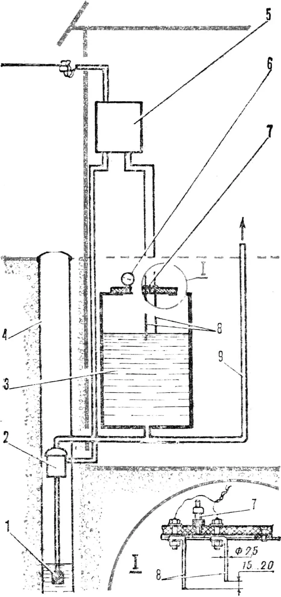
1 — water intake with check valve, 2 — electric pump, 3 — pressure tank, 4 — well, 5 — control unit, 6 — pressure gauge, 7 — valve, 8 — level sensors, 9 — distribution pipe.
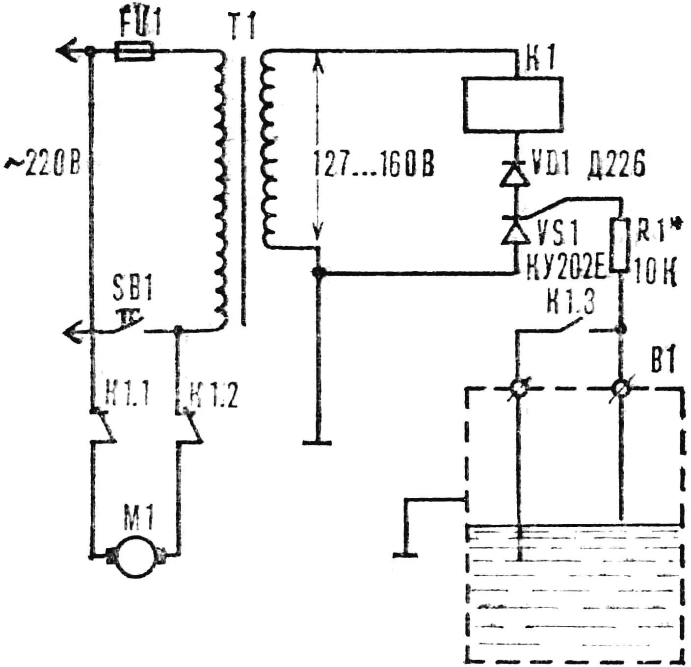
The electric pump is controlled by a simple thyristor device that automatically maintains a set water level. The sensors are two simple electrodes made of copper wire Ø 2.5 mm. They are bolted to the textolite lid of the tank so that the distance between their ends is 15—20 mm, and the upper one is at a level where the air in the tank is compressed to 1—1.5 atm.
The control system works as follows. When the water level in the tank reaches the upper, shorter electrode, the thyristor (see fig.) opens, the relay opens the contacts through which voltage was supplied to the pump motor. Simultaneously, a pair of normally open contacts connects the sensor electrodes together. As water is consumed and the level drops below both electrodes, the electrical circuit “electrodes — water — tank wall — ground” opens, the thyristor closes, and the relay releases the armature. The pump will turn on again and start supplying water.
A necessary condition for the system’s operability is the tightness of the pressure tank and the check valve of the water intake. Therefore, the lid is fastened to the tank with bolts through a rubber gasket. Holes for electrode bolts are drilled with minimal clearance and sealed with rubber washers during assembly. If compressed air leaks from the tank, the system pressure that determines the head can be restored by pumping air with a pump. For this, a bicycle or motorcycle inner tube valve is installed in the top lid. The pressure is sufficient for both household needs and garden irrigation.
V. BERDNIKOV, p. Vasilyevo, Zelenodolsky District, Tajikistan
“STARTER” FOR THE PUMP
I want to share experience with those who use centrifugal-type electric pumps to lift water from deep wells. For such a pump to always be ready for work, it must be constantly filled with water. But if the check valve of the water intake is not sufficiently tight, after stopping, water may leave the inlet pipe, which will complicate subsequent starting. A small system modification will help get rid of priming concerns. Install a small intermediate tank between the pump and the water intake, as shown in the figure.
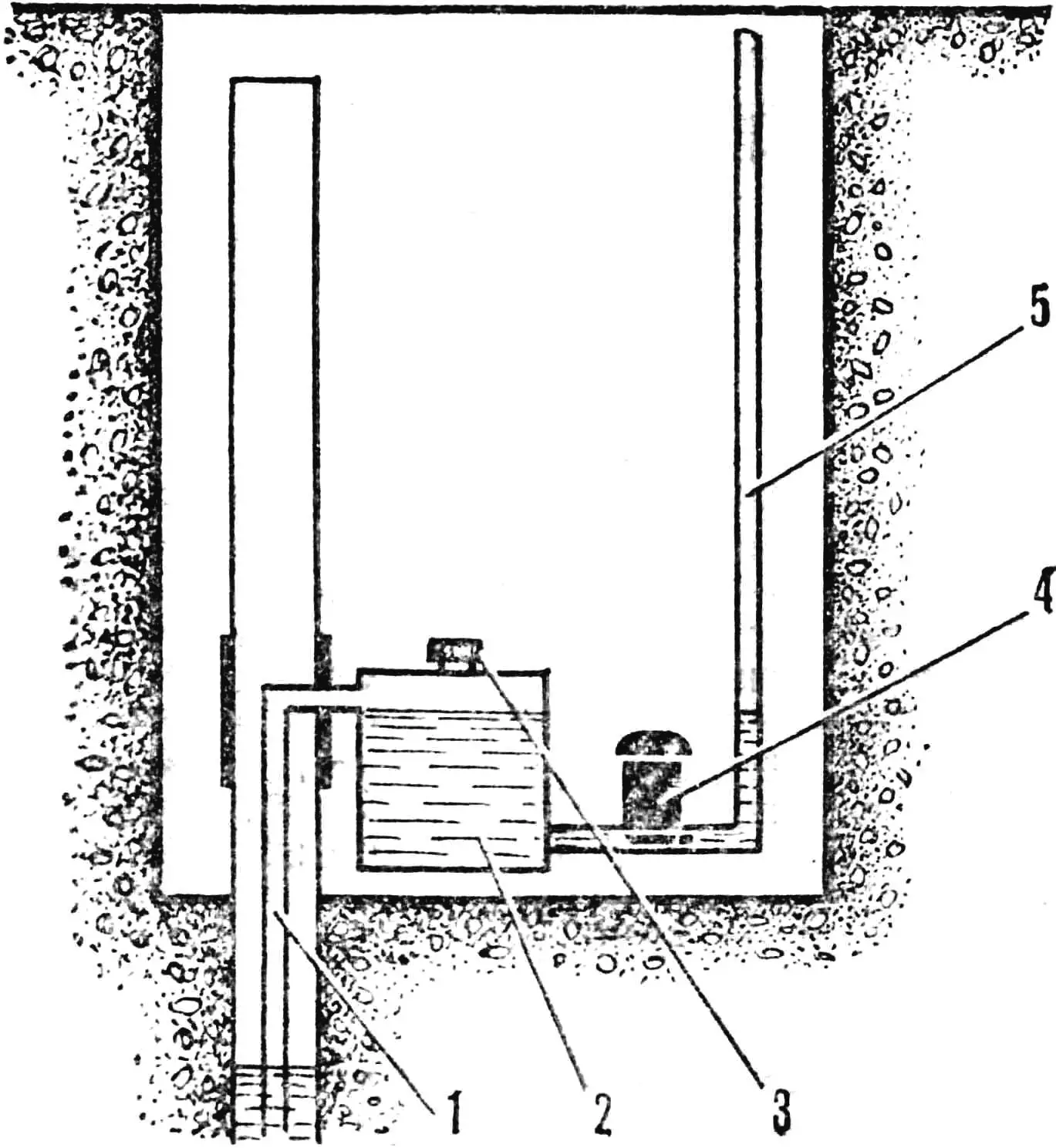
1 — water intake pipe, 2 — priming reservoir, 3 — fill neck, 4 — electric pump, 5 — pump outlet pipe.
Before the first start, fill this tank with water and tightly close the fill neck with a threaded lid with a gasket. Since the pump is connected to the lower point of the tank, and the water intake is to the upper one, water won’t leave there even with a faulty check valve, and the mechanism will always be ready for work. Moreover, if the tank is large enough, and the intake pipe is not from the very bottom point but with an offset of several centimeters from the bottom, the additional tank will also serve as a filter-settler.
«M-K» 5’86, A. POTAPOV
Recommend to read
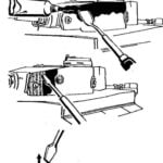 HOW TO MAKE “ZIMMERIT”
Anyone interested in the history of armored vehicles is well known that highly characteristic feature of the external appearance of the German tanks since 1943 was an anti-magnetic...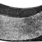 BATH-ROCKING CHAIR
The most popular formats of images of photographers ranging from 9X12 to 18X24 cm. This is for several reasons. First, prints of this size can be stored in albums, creating a...
