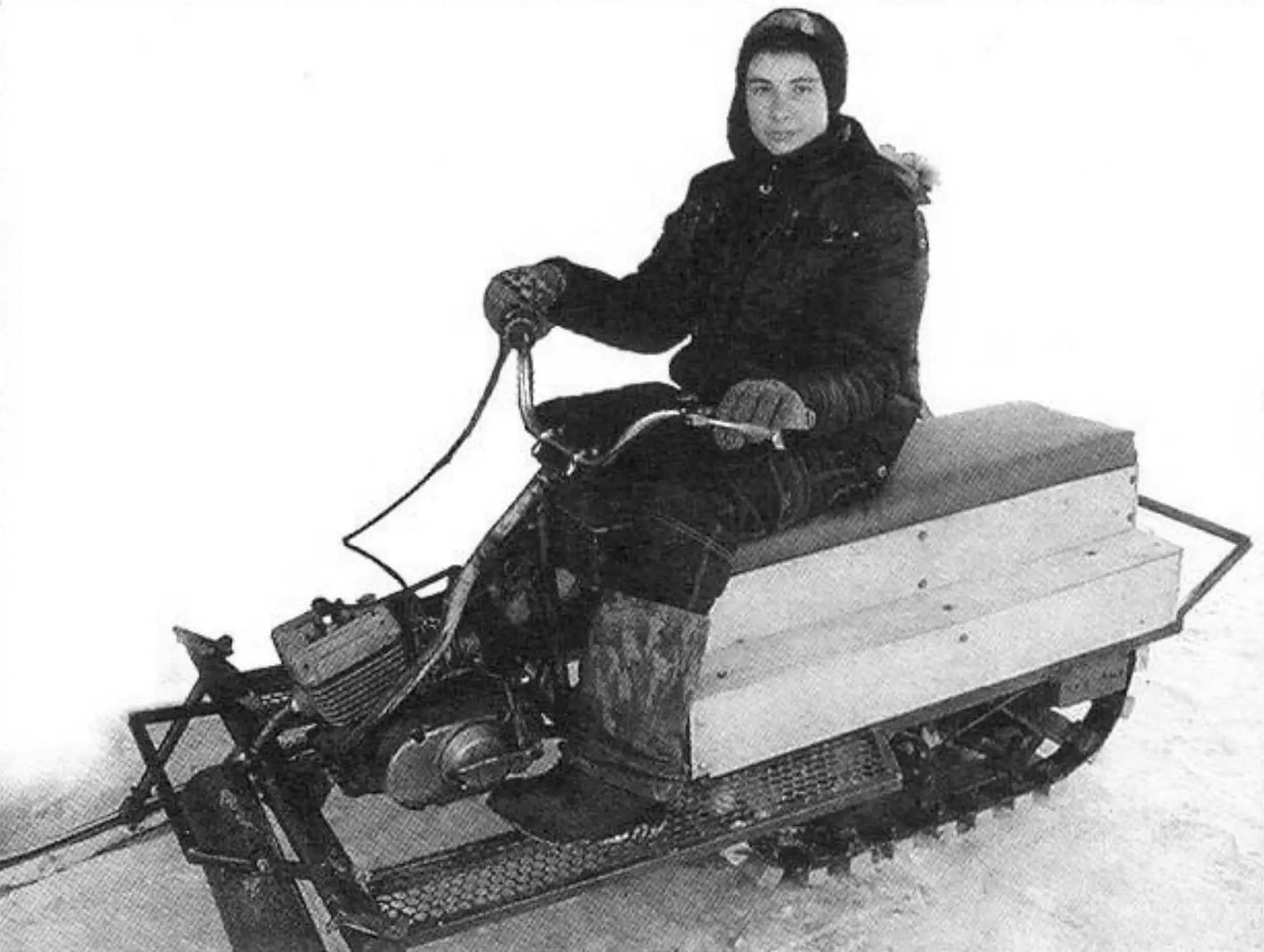
The snowmobile described in this story was built by tenth-grader Sergey Sorokin from the Altai village of Ust-Kamanka. And that is no surprise. The young man has been keen on machinery since childhood — for eight years he has been attending the CDT (Center for Children’s Creativity) in the “Small-Size Machinery” club. Club leader Viktor Alexandrovich Kurbatov helped with selecting drawings and designing the layout and transmission schemes of the machine. His father, Boris Andreyevich, helped with the critical welding work. Everything else, including machining parts on machine tools, he did himself. All in all, Sergey spent about a year building the snowmobile; assembly alone took nearly four months, from autumn to spring. And before the snow melted, he only managed to test it, “plowing” through all the snowdrifts around the house. But at least he has now found some shortcomings that he plans to fix before the next season.
Our parts are snowy, and winter lasts almost half a year. That is why every local boy dreams of a snowmobile — the machine’s ability to cross deep snowdrifts is impressive. A friend advised me to build a tracked snowmobile — he himself started making a similar machine in winter (though he later cooled off and abandoned it). Besides, I already had summer transport — a scooter. In spring I also began work, though slowly (and welding problems slowed it down further). Deciding on the design turned out to be easy — since I still had little experience, I decided to build one like those in the club: a three-support layout (with a track made of wooden bars on two conveyor-belt strips and two front steering skis). To simplify the design, I found it practical to make these support units without cushioned suspensions. In summer I prepared the belt and bars for the track and bought a used power unit from a Minsk motorcycle. The engine needed a new piston and rings. And in autumn, when we bought a welding unit, work on the snowmobile picked up pace.
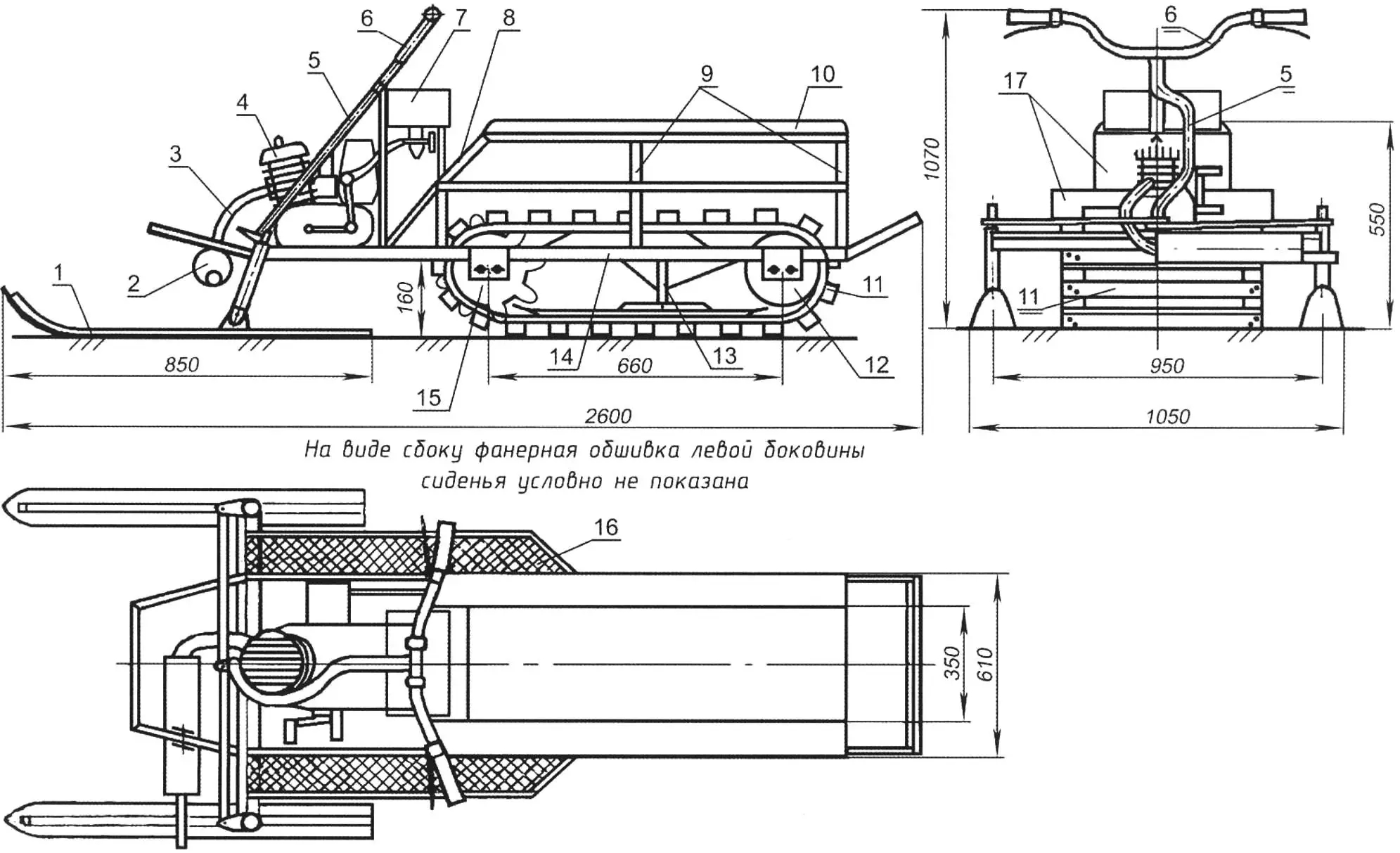
1 — guide ski (2 pcs.); 2 — muffler; 3 — exhaust pipe; 4 — engine (from a K-125 motorcycle); 5 — steering shaft (tube Ø22); 6 — handlebar; 7 — fuel tank; 8 — inclined seat strut (tube 20×20, 2 pcs.); 9 — vertical seat struts (tube 20×20, 4 pcs.); 10 — seat cushion (foam s50, covered with artificial leather); 11 — track; 12 — tension-axle assembly with two rollers); 13 — subframe with support ski and runners; 14 — frame; 15 — track drive-shaft assembly; 16 — footrest (stamped steel grate, 2 pcs.); 17 — seat-frame sheathing (plywood s5)
The snowmobile frame, though spatial, is simple — rectangular in plan. Its main load-bearing members (longerons and crossmembers) are welded from steel rectangular tubes 40×20 mm; the auxiliary ones are from square tubes 20×20 mm. The front crossbeam is made from a 60×30 mm tube and welded to the front ends of the longerons at a 15-degree angle (the angle between the longer tube wall and the horizontal). In general, all crossmembers except the first are made as portals (U-shaped, but on short posts). At first I made the portal-crossmember posts slightly tilted inward (I thought it would look nicer), but tests showed that the ends of the track bars started catching on them. I would have had to shorten the already not-very-long track bars, so I decided it was better to reweld the portals and make them rectangular.
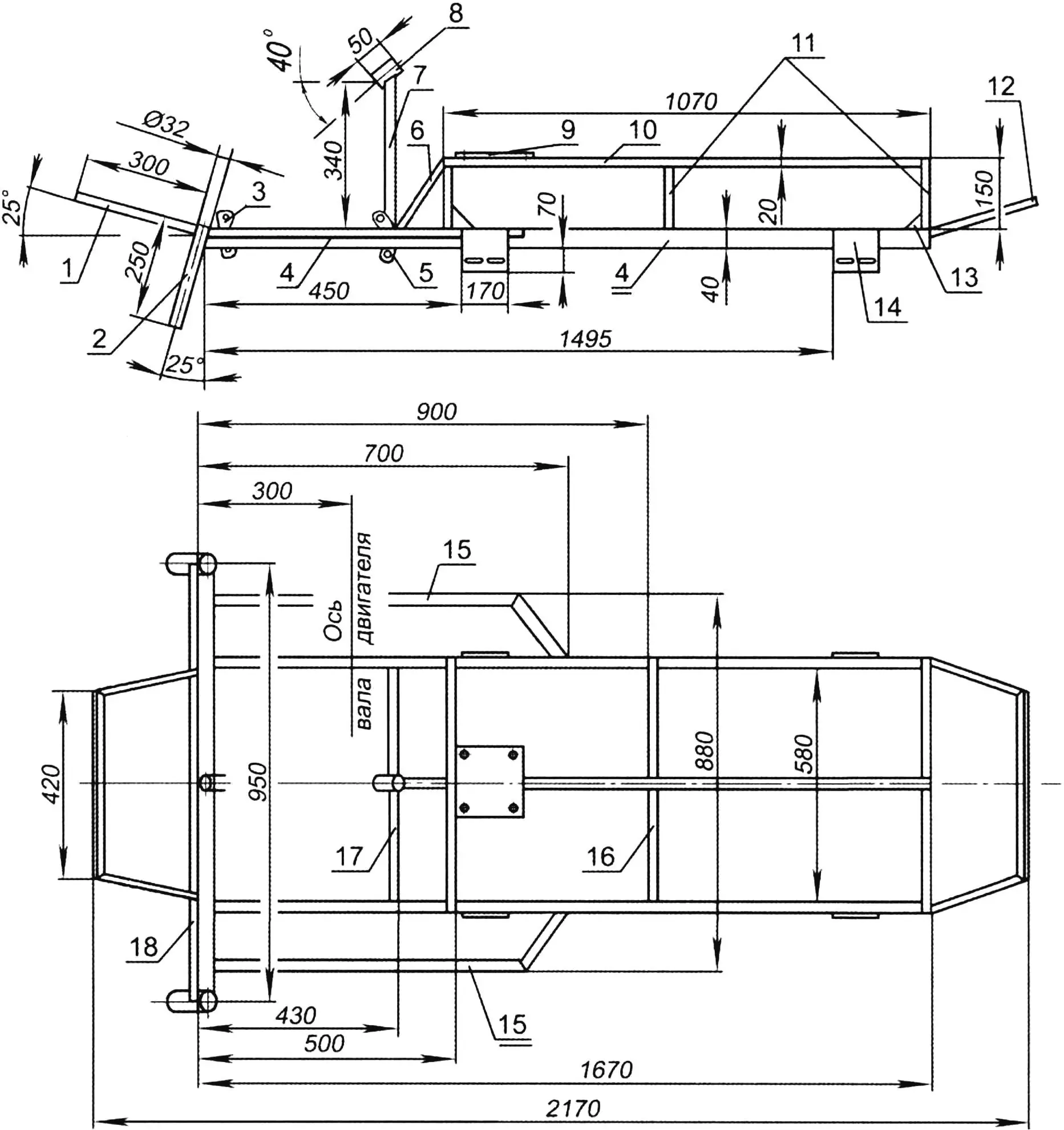
1 — front bumper (steel tube 20×20); 2 — steering-knuckle bushing of the guide ski (tube Ø22, 2 pcs.); 3 — front power-unit mounting lug (steel sheet s4); 4 — longeron (tube 40×20, 2 pcs.); 5 — rear power-unit mounting lug (steel sheet s4); 6 — brace (steel tube 20×20); 7 — support strut of the steering-shaft bushing (tube 20×20); 8 — steering-shaft bushing (tube Ø28); 9 — seat backing plate (steel sheet s2); 10 — ridge cross-link (tube 20×20); 11 — portal posts (tube 20×20, 6 pcs.); 12 — rear bumper (tube 20×20); 13 — gusset (steel sheet s4, 4 pcs.); 14 — bracket for mounting the drive shaft and track tension axle (steel sheet s4, 4 pcs.); 15 — footrest frame (tube 20×20, 2 pcs.); 16 — portal cross-link (tube 20×20, 3 pcs.); 17 — support crossmember (tube 20×20); 18 — crossbeam (tube 50×30)
The housings of the steering knuckles of the steered skis can also be considered frame parts. The housings are made from steel tube with an outside diameter of 32 mm and a wall thickness of 5 mm and are welded to the ends of the crossbeam at 15 degrees to the vertical.
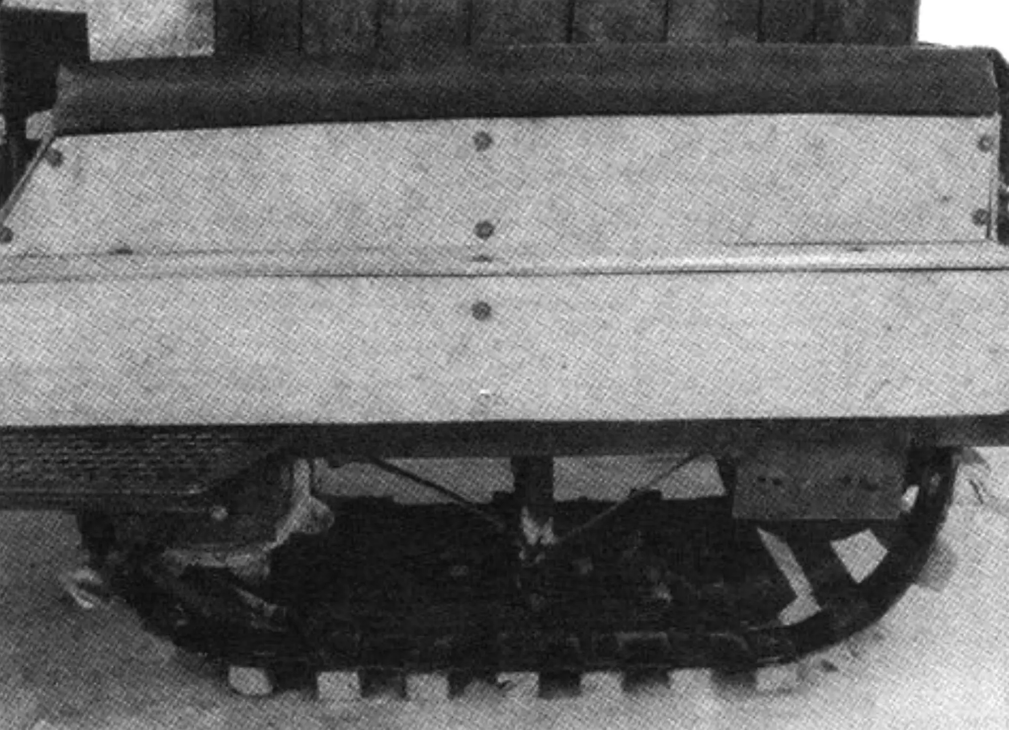
The tracked drive is like those used by most DIY builders. Its track is a pair of parallel endless strips (with riveted ends) of conveyor belt 65 mm wide that join wooden track bars of 50×40 mm cross-section, fastened to them at a 100 mm pitch. The overall track length is a little over two meters, and it has 20 track bars. To keep the track from “drifting” sideways, steel angles are fixed on the free side of the bar ends (every one or two bars). Each angle is a welded part, and their vertical flanges are made rounded (from tube) so that the angles themselves cannot jam on the support ski or the drive sprocket wheels.
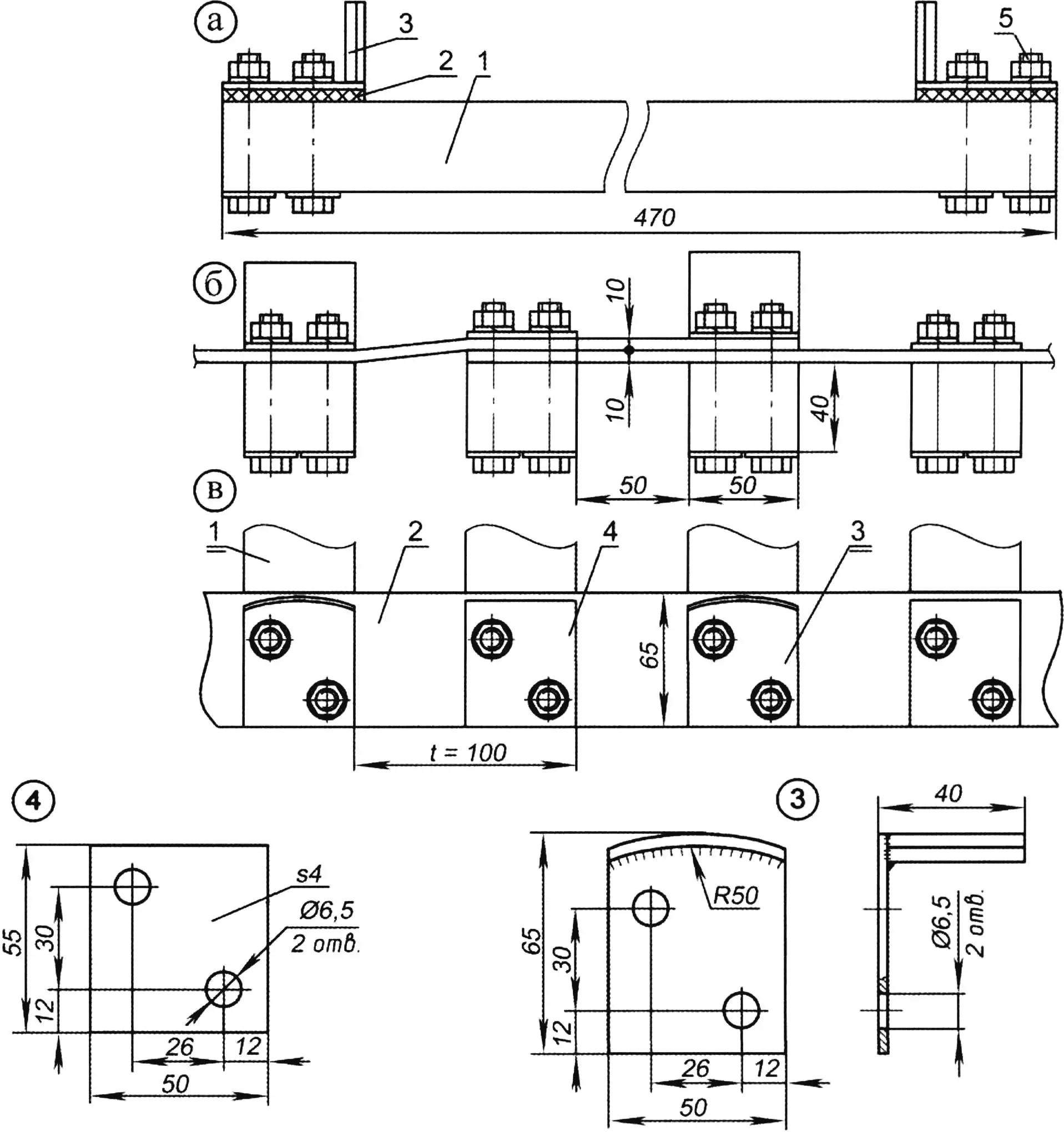
1 — track bar (birch timber 50×40, set); 2 — strip (conveyor belt 65×10, 2 pcs.); 3 — stop (steel sheet s4, set); 4 — plate (steel sheet s4, set); 5 — M6 bolt with plain and spring washers, set)
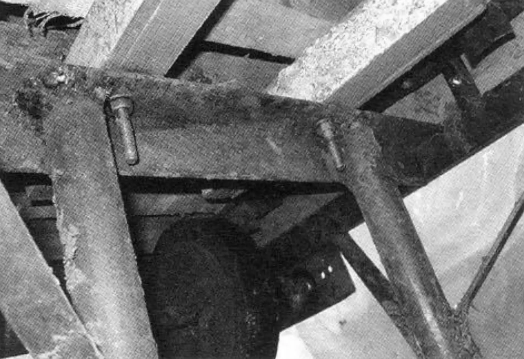
The lower run of the track is supported by a support ski, and two wooden runners of 50×50 mm cross-section keep the upper run from sagging. The ends of the runners are beveled for easier entry onto them and quiet exit of the track. The support ski is made of 5 mm sheet polyethylene on a base of 2 mm steel sheet with a frame of No. 2 angle. At the front and rear it has upward bends. Snow itself serves as lubrication when the track bars slide over the support ski and runners; practice shows that this gives the parts a service life of one or two seasons (depending on how intensively they are used), after which they have to be replaced. The support ski in the subframe is hinged to a pair of posts whose other ends are welded to an additional frame crossmember made of 50×50 mm rolled angle. But on the very first tests the posts began to bend. They had to be reinforced with braces of 30×4 mm steel strip. The runners are mounted parallel to the longerons and bolted rigidly to the additional frame crossmember with M10 bolts.
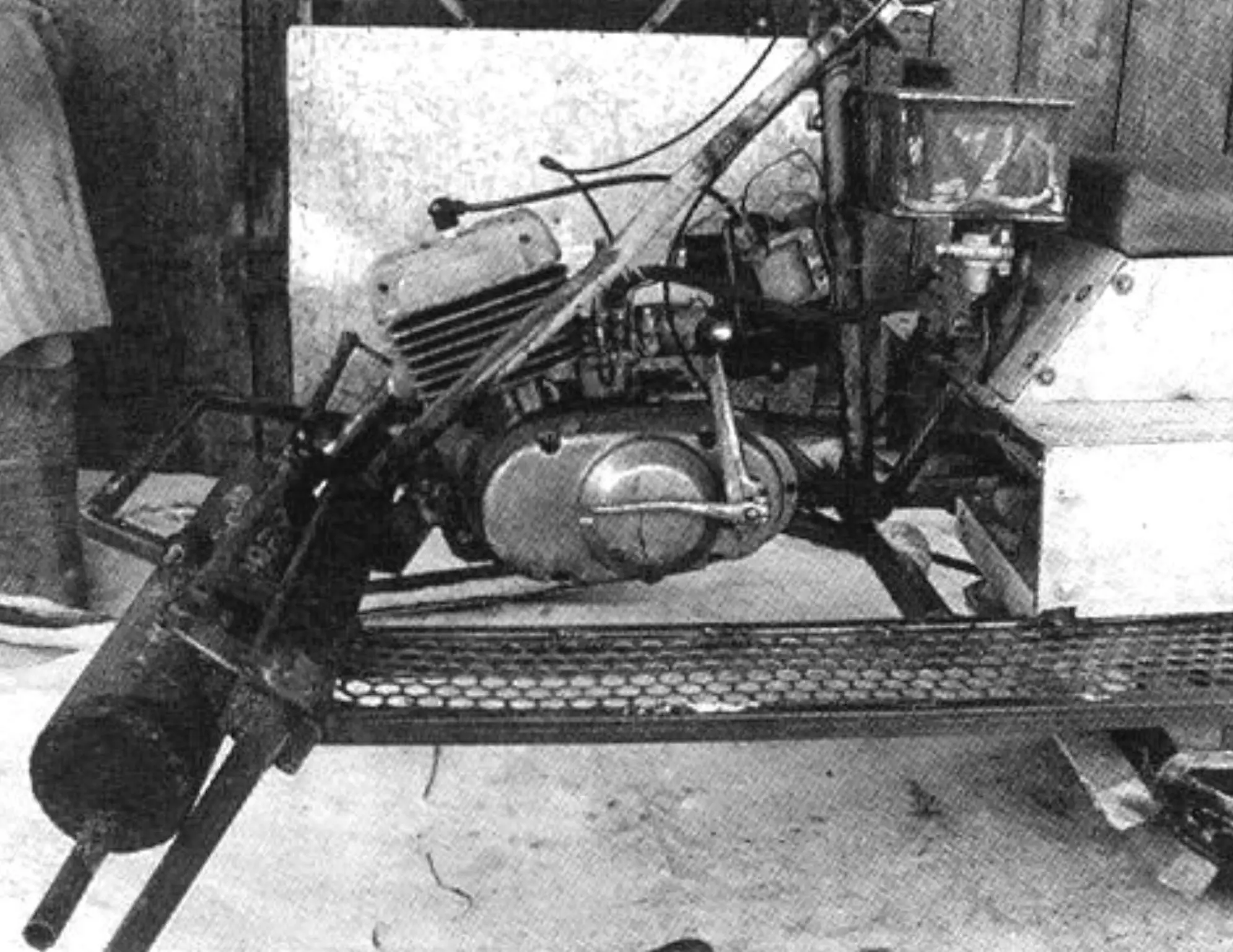
The power unit, as noted above, is from a Minsk motorcycle (two-stroke, 125 cm³ displacement and 10 hp). I placed it at the front, in the middle of the frame. This layout meant I did not have to worry about weight distribution of the unit, but it forced me to make a “bent” steering shaft so that on turns it would clear the engine cylinder without hitting it. I fastened the engine to the frame with a pair of lug brackets cut from 4 mm steel sheet to the shape of the stock ones welded to the motorcycle frame. The motor was not modified in any way; even the output-shaft sprocket remained stock, with fifteen teeth.
Fuel (a mixture of gasoline and two-stroke engine oil) is fed to the engine carburetor by gravity from a homemade 5-liter fuel tank located above the engine between the handlebar and the seat.
The snowmobile transmission is also the simplest kind — with no intermediate shaft or gearbox. A chain drive from the output shaft transmits rotation directly to the drive sprocket of the track shaft, on which a pair of track drive sprocket wheels is mounted. I cast the sprocket wheels in the club from aluminum melted in an electric furnace into a cast-iron mold. They are joined to the shaft through round steel flanges welded to it, each with four M8 bolts.
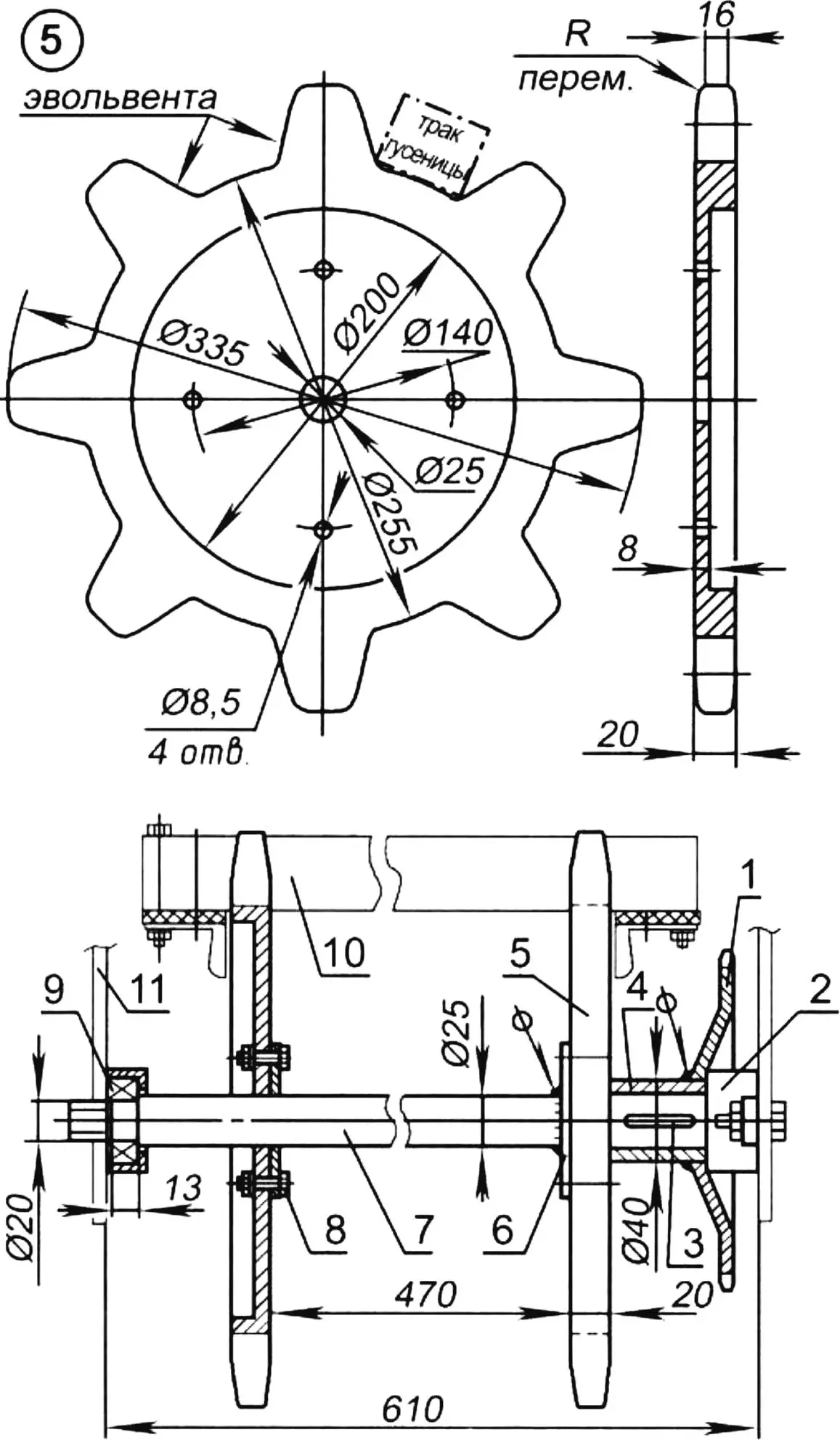
1 — drive sprocket of the track drive shaft (z=32); 2 — housing of bearing No. 205 (2 pcs.); 3 — key; 4 — drive-sprocket hub (tube Ø40×7.5); 5 — sprocket wheel z=8, t=50 (duralumin); 6 — flange for fastening the sprocket wheel to the shaft (steel sheet s4, 2 pcs.); 7 — shaft (steel, round bar 25); 8 — bolt M8x25 (8 pcs.); 9 — bearing No. 205 (2 pcs.); 10 — track; 11 — bracket for fastening the shaft to the frame
The shaft turns in two No. 203 bearings whose housings are fixed on plate brackets of the frame intended for them (welded to the longerons). The tension axle is made like the drive shaft, only instead of drive sprocket wheels it carries two rubberized rollers of smaller diameter.
The chain is tensioned (or loosened for removal) by shifting the drive shaft farther from the power unit, and the track by shifting the rear tension axle still farther back.
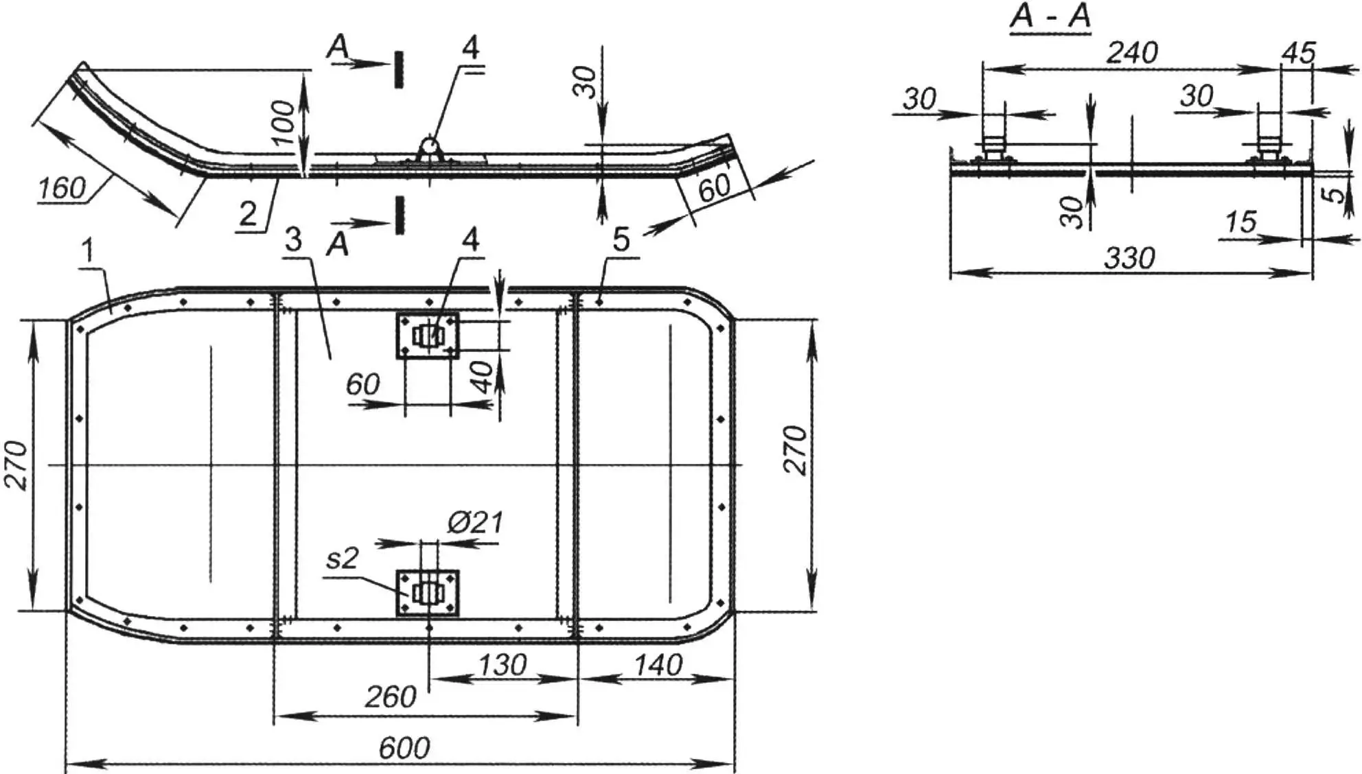
1 — frame (steel angle No. 2); 2 — sole (polyethylene s5); 3 — base (steel sheet s2); 4 — bracket (2 pcs.); 5 — rivets (heads countersunk from below, set)
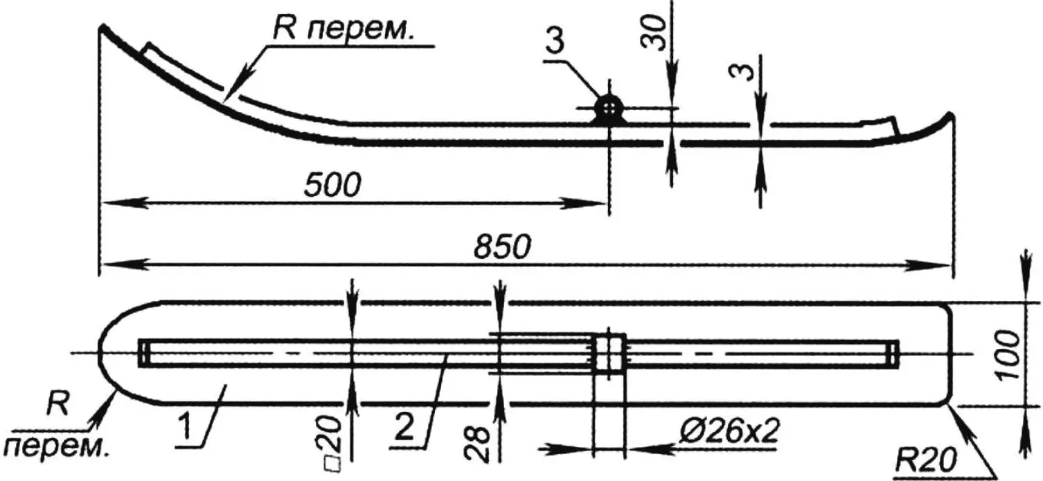
1 — runner (steel sheet s3); 2 — ridge (steel tube 20×20); 3 — bushing (steel tube Ø26×2)
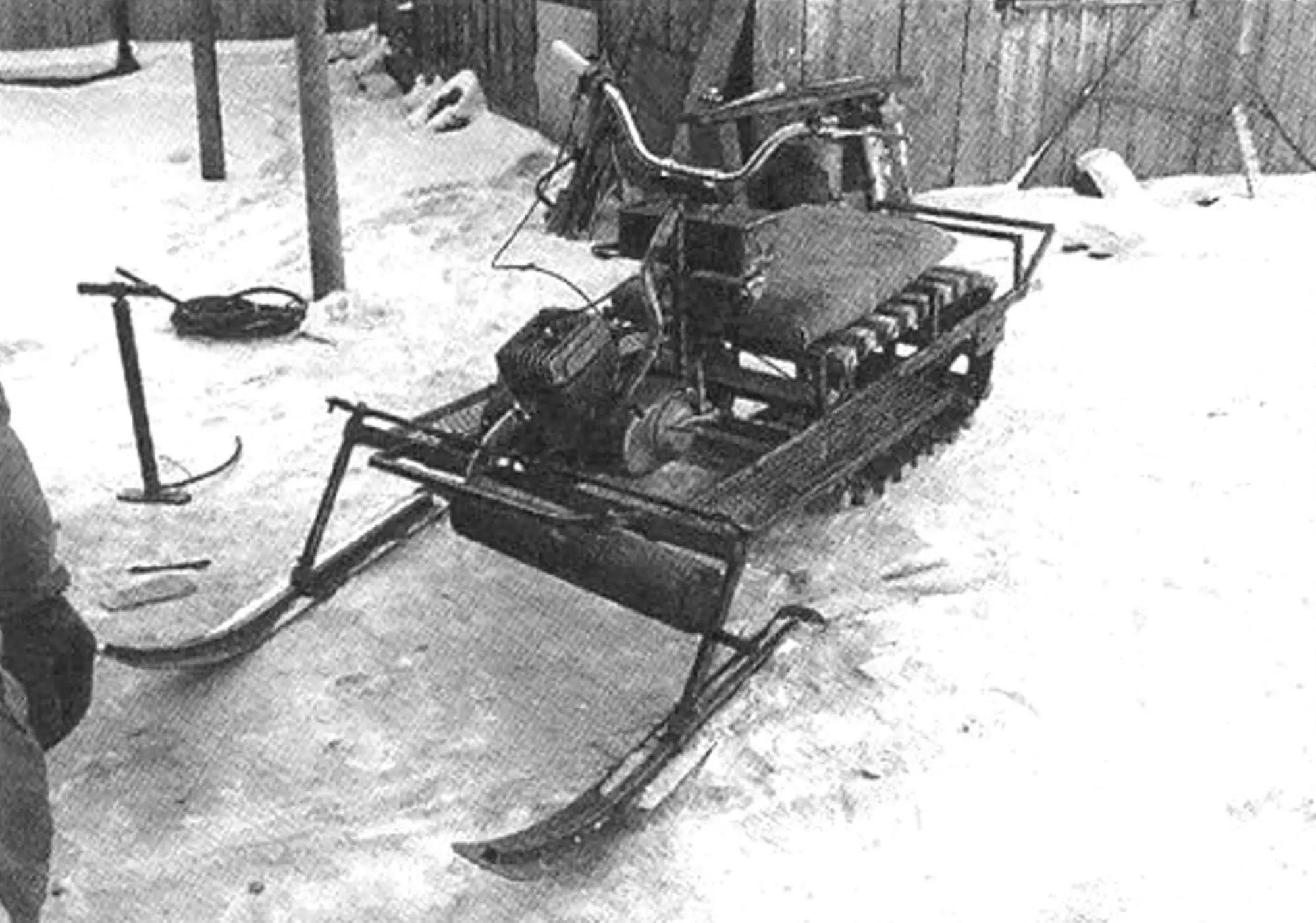
The guide skis (there are two) are made of 3 mm steel sheet and reinforced by a longitudinal stiffener of 20×20 mm steel tube welded on top. The ski is hinged to the steering-knuckle post and can pivot in the vertical plane — climb onto obstacles and ride over them. In the horizontal plane the ski turns with the knuckle under the action of the steering rods when the handlebar is turned. The skis have no keels (or “knives,” as they are often called), but this does not affect handling much because the skis themselves are quite narrow.
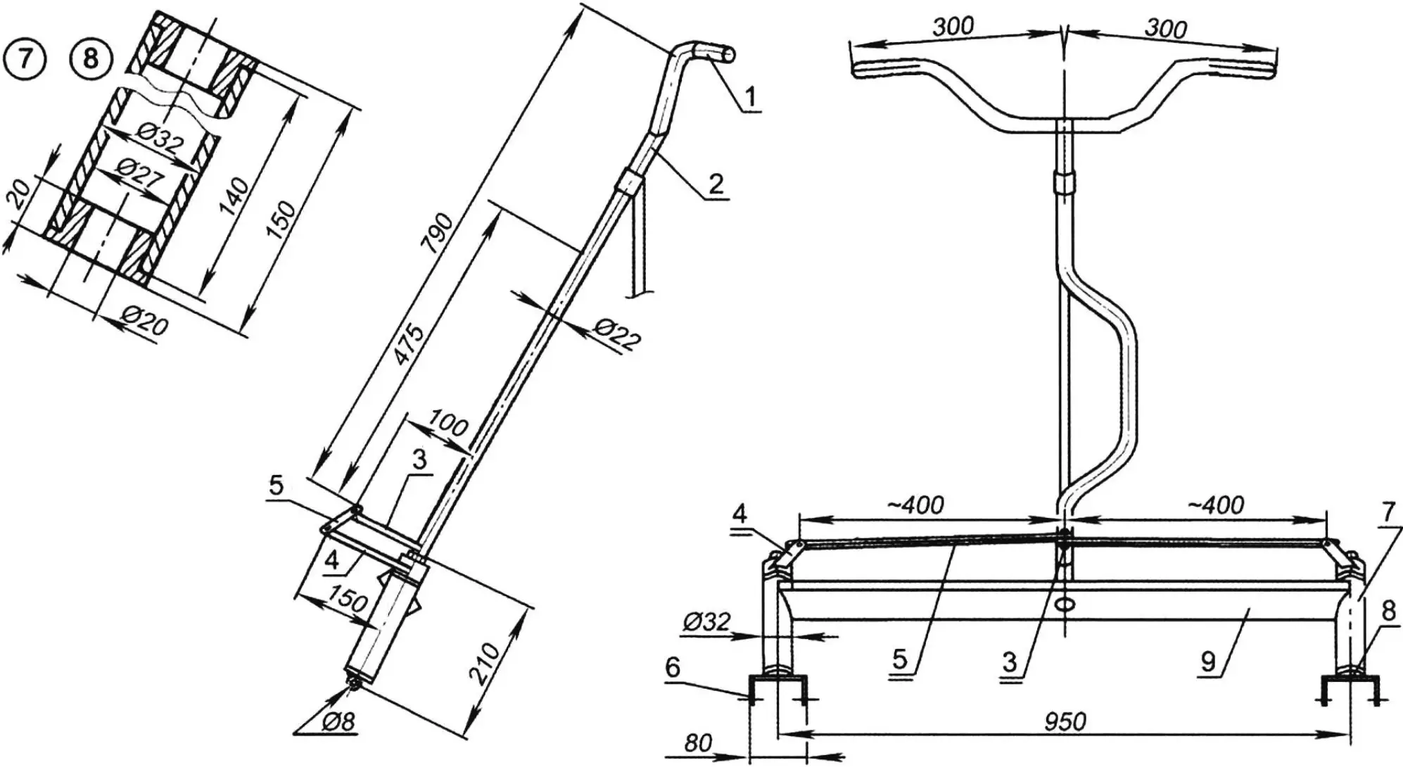
1 — handlebar (from a Minsk motorcycle); 2 — steering shaft (steel tube Ø22×2); 3 — steering arm (steel sheet s4); 4 — steering-knuckle lever (steel sheet s4, 2 pcs.); 5 — transverse rod (steel sheet s4, 2 pcs.); 6 — kingpin with fork (2 pcs.); 7 — steering-knuckle housing (steel tube Ø32×5, 2 pcs.); 8 — plain bearing (kapron, 4 pcs.); 9 — crossbeam
The steering is typical of snowmobiles with two steered skis and of ATVs: a motorcycle-type handlebar, a steering shaft with an arm, and the transverse rods with steering knuckles already of the automotive type. The special feature of the steering shaft was noted above — it is “bent.”
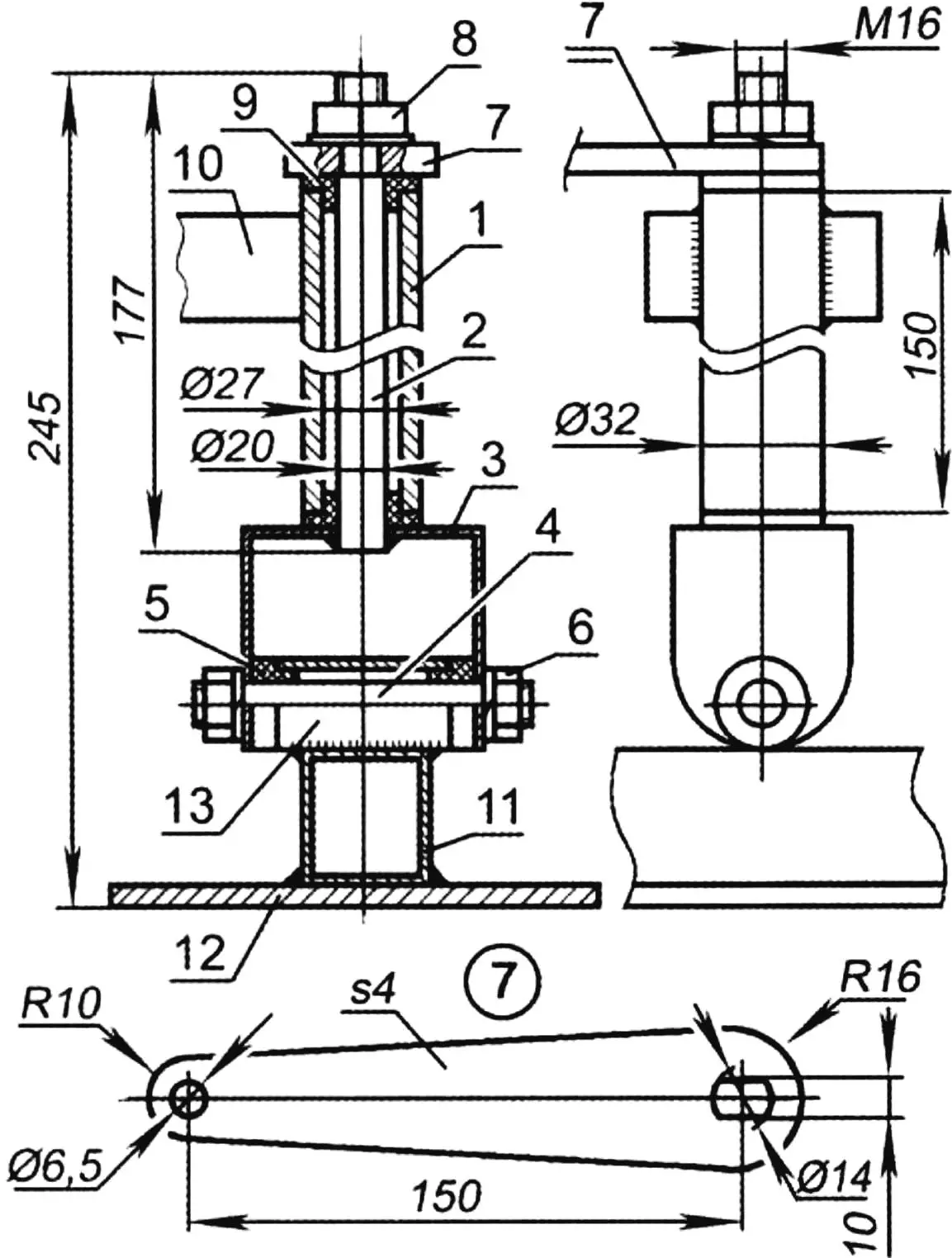
1 — steering-knuckle housing; 2 — kingpin (steel, round bar 16, 2 pcs.); 3 — fork (channel No. 5); 4 — knuckle axle (steel, round bar 16, 2 pcs.); 5 — axle plain bearing (kapron, 2 pcs.); 6 — M16 nut with spring washer for axle fastening (2 sets); 7 — steering-knuckle lever (steel sheet s4); 8 — M16 nut with spring washer for lever fastening; 9 — kingpin plain bearing (kapron, 4 pcs.); 10 — frame crossbeam; 11 — ski stiffener (ski ridge); 12 — ski runner; 13 — ski bushing
The snowmobile has no brakes, but it stops fairly quickly thanks to friction in the track unit and transmission when the throttle is closed.
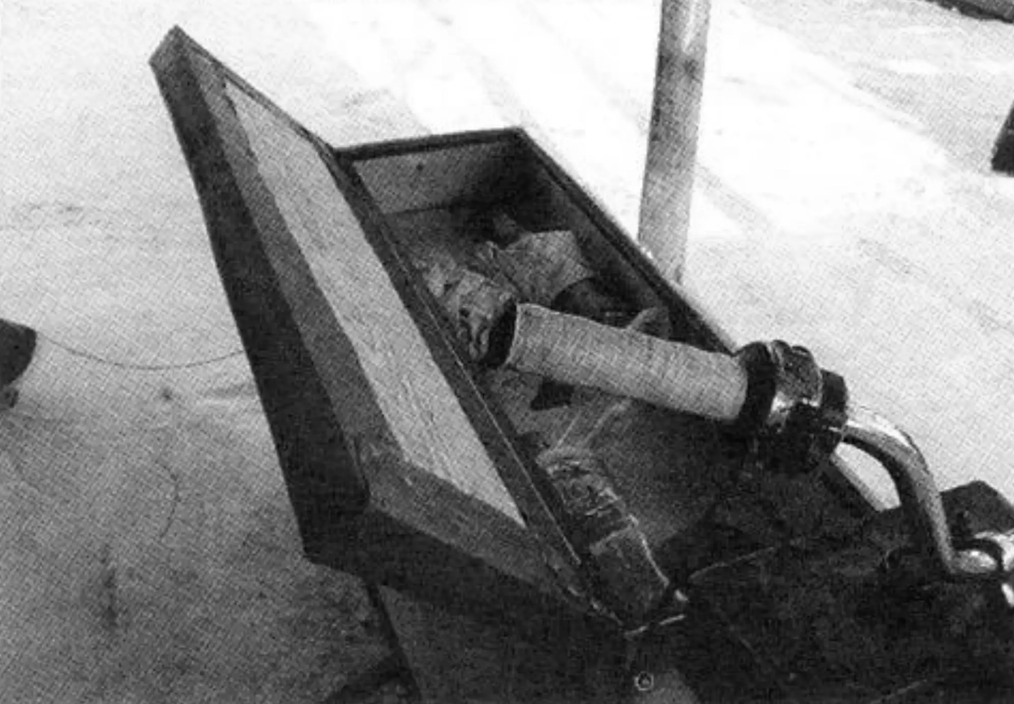
And although my snowmobile is a simplified design with quite a few shortcomings, it delights me with its enviable cross-country ability over snowy virgin land and snowdrifts. That is why I named the snowmobile “Sugrober KM-125” — the conqueror of snowdrifts.
“Modelist-Konstruktor” No. 8’2012, S. SOROKIN, Altai
Recommend to read
 PENCIL — FOR A MOMENT
If the drawer have a lot of pencils, markers and pens — do yourself here's a handy table pencil. It will require a minute of free time, plastic, ceramic or glass jar and strips of thick... “ELECTROMAN” FOR RATS
Many people keep different Pets, communication with which brings a lot of pleasant moments for both children and adults. However, there are those animals, which are also constantly live...
