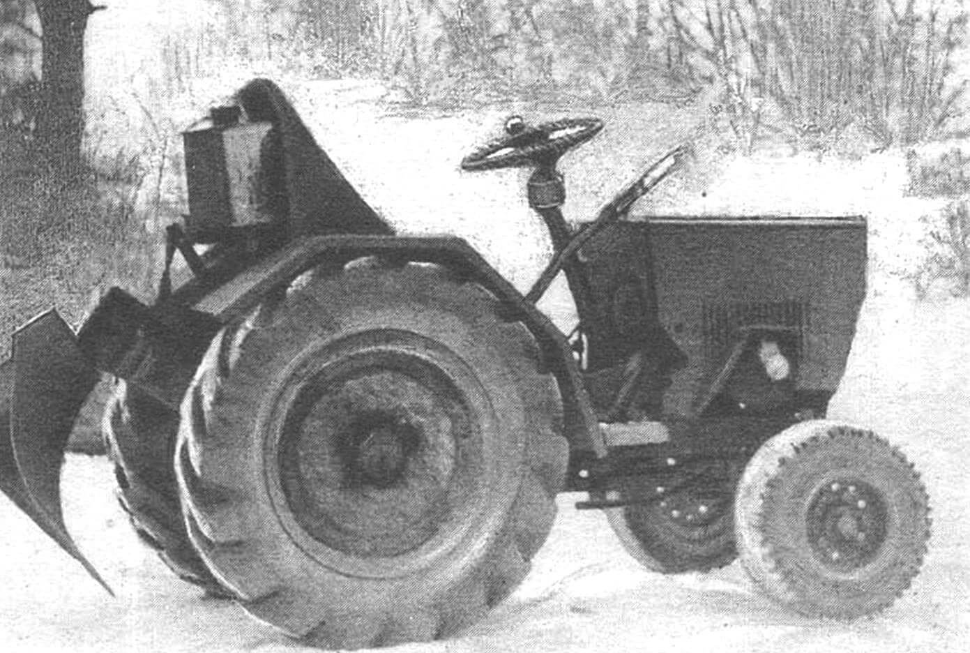
For enthusiasts who enjoy crafting and working with agricultural machinery, I consider myself among them for many years. Being a regular reader of “Modelist-Constructor,” I have manufactured (with the help of journal developments) a mower, a mini-moped for hay transportation, an all-terrain vehicle on pneumatics, several mini-tractors, and my best DIY creation, in my opinion, is a design that has been willingly replicated by neighbors and has never let anyone down. I present it to the judgment of the readers.
Of course, it’s the hardworking mini-tractor. Compact in size, agile, equipped with a reverse gearbox, as I have already described (with sketches and other materials) in the pages of the 11th issue of the journal in 1989.
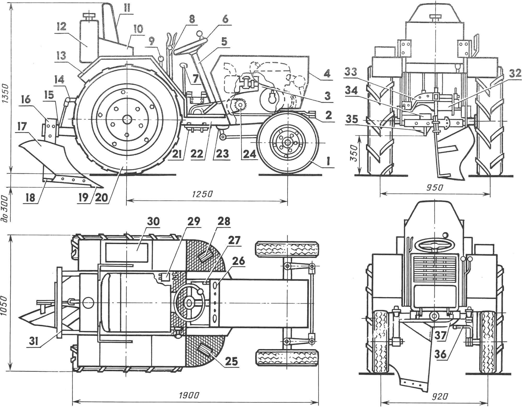
1 — front wheel with pneumatic tire 5.0–10″ (2 pcs.), 2 — steering trapeze (from motorized cart C3A), 3 — power unit (from motorized cart C3A), 4 — homemade tilting hood, 5 — steering column (from GAZ-21 “Volga” car), 6 — steering wheel with “ball” handle (from a forklift), 7 — “reverse” lever, 8 — lift lever for hitch frame (with fixation, from LiAZ bus), 9 — brake engagement levers (right and left), 10 — fuel tank bracket (2 pcs.), 11 — seat, 12 — fuel tank, 13 — mudguard (2 pcs.), 14 — hitch frame lifting mechanism (lever), 15 — plate for attaching mounted implements, 16 — plow body, 17 — grader blade, 18 — field board, 19 — plowshare with extended tip, 20 — rear wheel drive with pneumatic tire 6.5–20″ (2 pcs.), 21 — homemade reverse gearbox (description and sketches of the design in No. 11’89), 22 — MT frame, 23 — steering mechanism (from GAZ-21 “Volga” car), 24 — power transmission with PR-19.05 chain (from retired agricultural machinery), 25 — “clutch” pedal, 26 — instrument panel, 27 — kickstarter lever, 28 — “gas” pedal, 29 — master cylinder of the main brake hydraulic drive, 30 — toolbox, 31 — hitch frame, 32 — welded support of the hitch frame lifting mechanism, 33 — pulley, 34 — towing device, 35 — rear axle (from GAZ-21 “Volga” car, shortened), 36 — steering yoke, 37 — bracket for reverse gearbox.
I had to struggle quite a bit with the kinematics of the transmission before finding a simple and acceptable solution for the available “material base” (see illustration). The same can be said about the layout. Although individual elements of the design turned out to be somewhat heavy and low, they are not lacking in strength. The mini-tractor (hereinafter referred to as MT) works reliably when transporting loads weighing up to one ton, during hay harvesting (with a hitched horse-drawn mower), plowing, and furrowing. During plowing, either the second or third speed is used depending on the soil’s hardness. And they are significant. A regular horse plow, as it turned out, is almost unacceptable here, so I had to make my own: slightly larger in size, with an extended plowshare tip, and a smaller angle of the blade (see illustration).
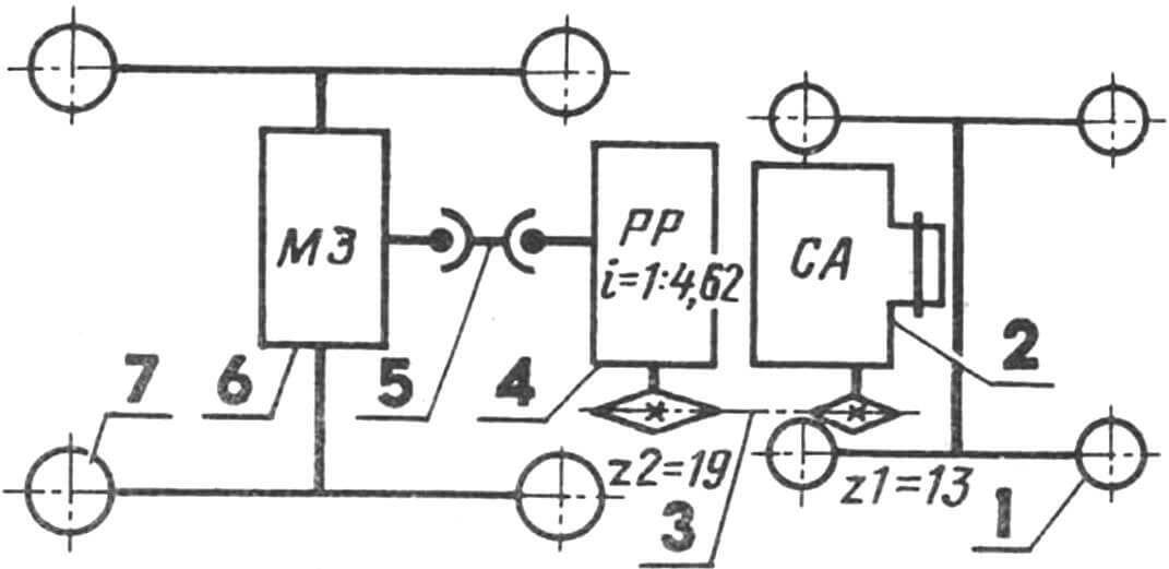
1 — front driven wheel (from motorized cart C3A, 2 pcs.), 2 — power unit (from motorized cart C3A), 3 — power transmission with PR-19.05 chain (from retired agricultural machinery), 4 — homemade reverse gearbox (description of the design and sketches of the main parts and assemblies in No. 11’89), 5 — cardan shaft transmission, 6 — rear axle (from GAZ-21 “Volga” car, shortened), 7 — rear driving wheel (from MTZ-52 tractor, 2 pcs.).
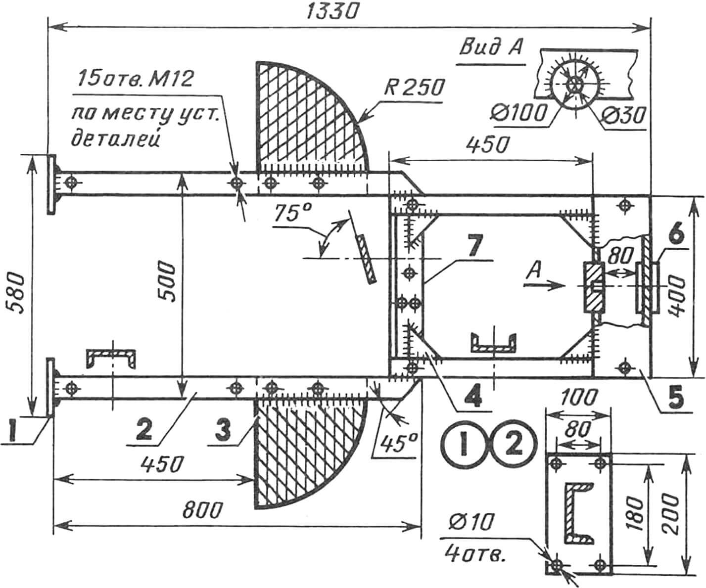
The main structure of the MT is its frame. Without welding, of course, such a frame cannot be made. Increased strength is given by channel-section longitudinal beams, the crossbeam-bracket of the front axle (made from the same 16 mm steel channel), diagonal braces made of 5 mm St3 steel, and a “rotatable” bracket for the steering column welded in place. And, of course, the rear axle. Firmly attached to the longitudinal beams with 8 mm steel plates tightened with eight M10 bolts with nuts, secured with Grover washers, it is a kind of logical continuation and completion of the welded frame.
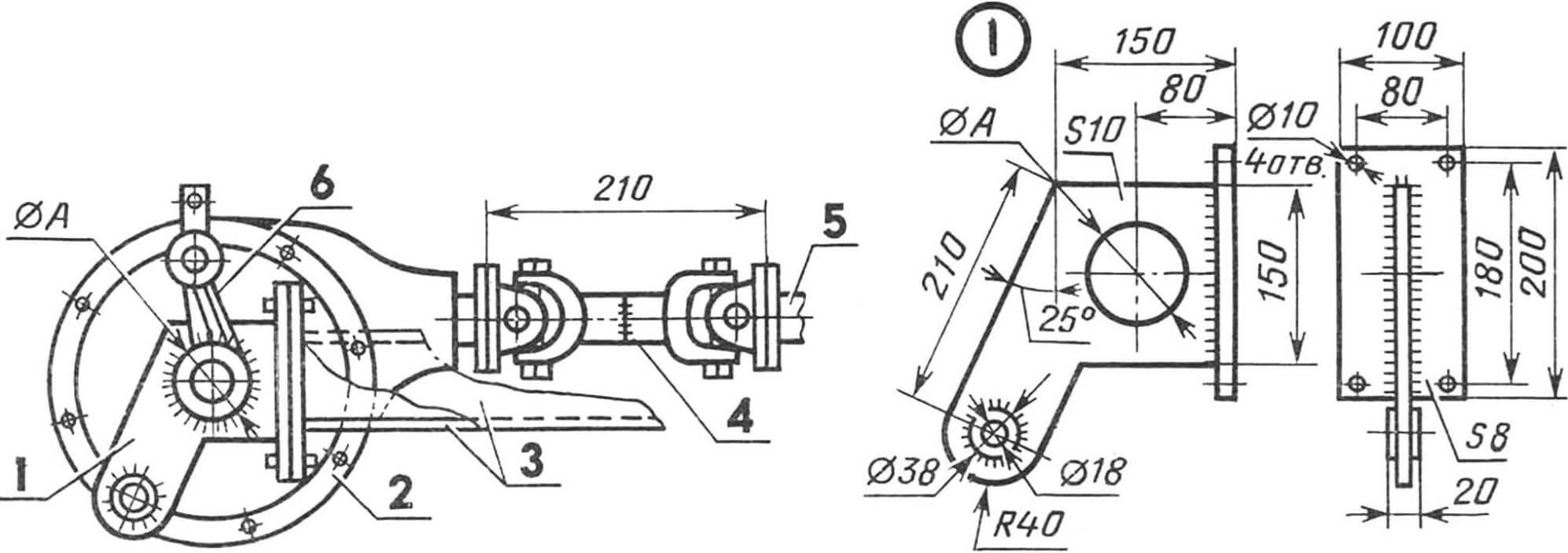
1 — homemade hitch bracket (St3, 2 pcs.), 2 — rear axle (from GAZ-21 “Volga” car, shortened), 3 — MT frame longitudinal beams, 4 — cardan transmission (shortened cardan shaft), 5 — output shaft of the reverse gearbox, 6 — welded support of the hitch frame lifting mechanism (from retired agricultural machinery).
The rear axle is from the GAZ-21 “Volga” car, shortened (cut) to a width (flange to flange) of 800 mm (following a methodology similar to what was published in the 2nd issue of the journal in 1993). I will note only that the heads of the rivets fixing the shafts were cut off. The remaining part was pushed inside the shaft.
The pressing out of the shafts from the differential housing of the rear axle was quite easy, using special mandrels and… a hammer. The shafts were machined so that the finished axle had different lengths of shafts and matched as well as possible with the reverse gearbox (also shifted to the left, looking in the direction of MT movement in normal mode). This allows reducing the cardan’s deflection and increasing the load on the left rear wheel during plowing. There is no need to install additional counterweights; the tractor is stable in the furrow.
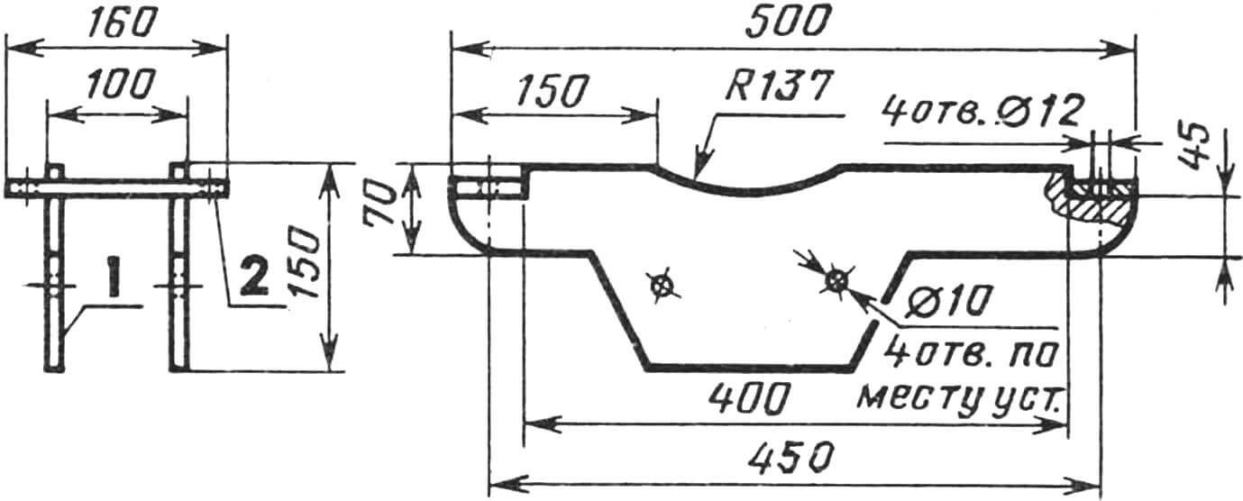
1 — crossmember (2 pcs.), 2 — base (2 pcs.).
But I will continue with the improvement of the rear axle. In the holes left after the rivets, M12 threads are tapped to fix the shortened axle.
When performing a complex of works on such an axle, brackets for the suspension and plates for attaching it to the frame were immediately welded in. Also, brackets for attaching the tow hitch to the axle housing were welded, as well as the housing of the lifting unit.
The hitch frame is a welded structure made of sections of channel and steel angles No. 8 with brackets and reinforcement plates. The latter are made of 5-mm St3. There are also 2 lugs (rings made of 8-mm St3) on the frame. This frame is attached movably to the brackets of the suspension (see illustration). The box-like part of it is used for mounting mounted implements. It can be a plow, hilling tools, rakes, or cultivators.
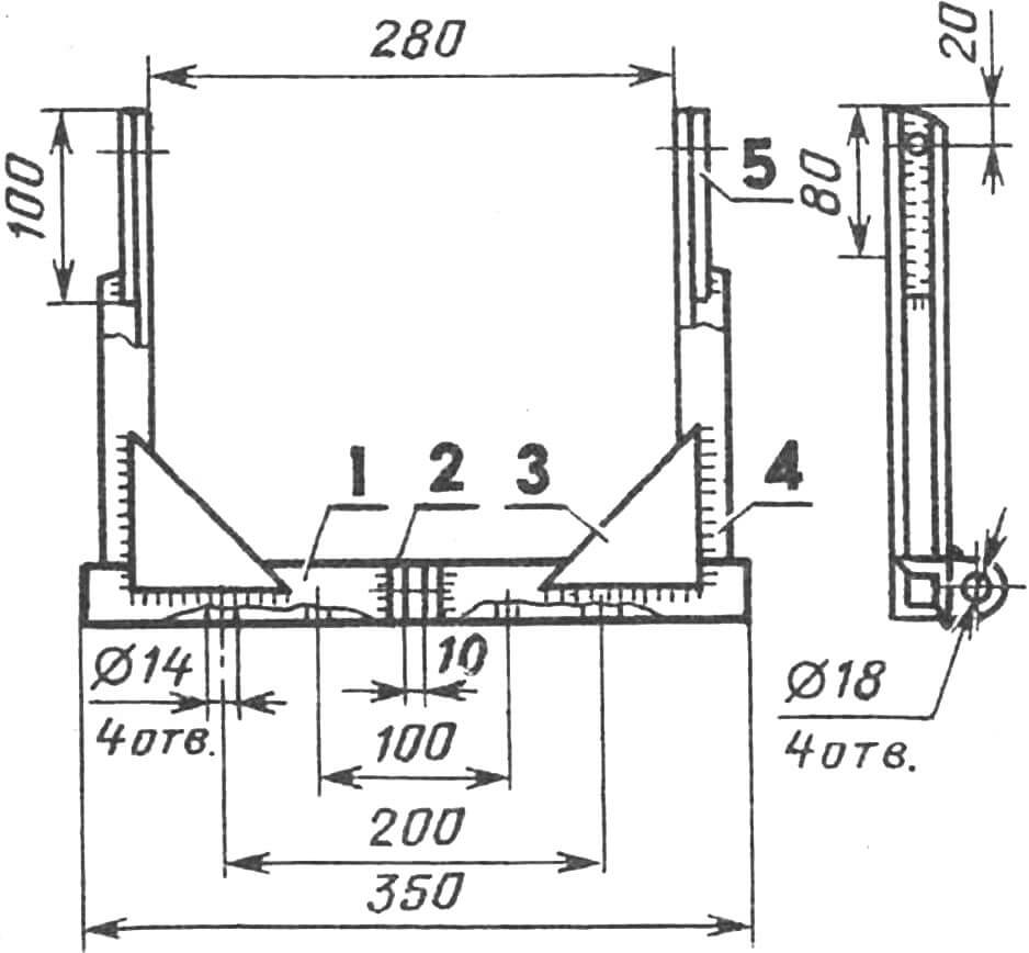
1 — beam for attaching mounted implements (from a section of square tube 50×5 or box-welded two steel angles No. 8), 2 — lug (ring made of 8-mm St3, 2 pcs.), 3 — bracket (5-mm St3, 2 pcs.), 4 — spar (from a section of channel 8 steel, 2 pcs.), 5 — reinforcement plate (5-mm St3, 2 pcs.).
The raising and lowering of all this is carried out using a compact and reliable lever system. Moreover, the lever for lifting the hitch frame has a fixing “dog.” Borrowed from a decommissioned LiAZ bus.
The front axle is made using both ready-made units-parts (from decommissioned auto-tractor equipment) and homemade ones. Among the latter, for example, are the front wheel axle bushing and the support-rotary rack bushing. In this list, there is also the beam of the front axle. It is made from a section of square tube 65×5 or two box-welded steel angles No. 6.3. In the center of it, a ready-made unit of two tapered roller bearings 2507 is inserted and welded. Such a beam is installed on a bolt axis in the recess formed by the bushings welded to the cross member of the front axle frame bracket. The play is adjusted here by tightening the M30 nut, under which a Grover washer is placed.
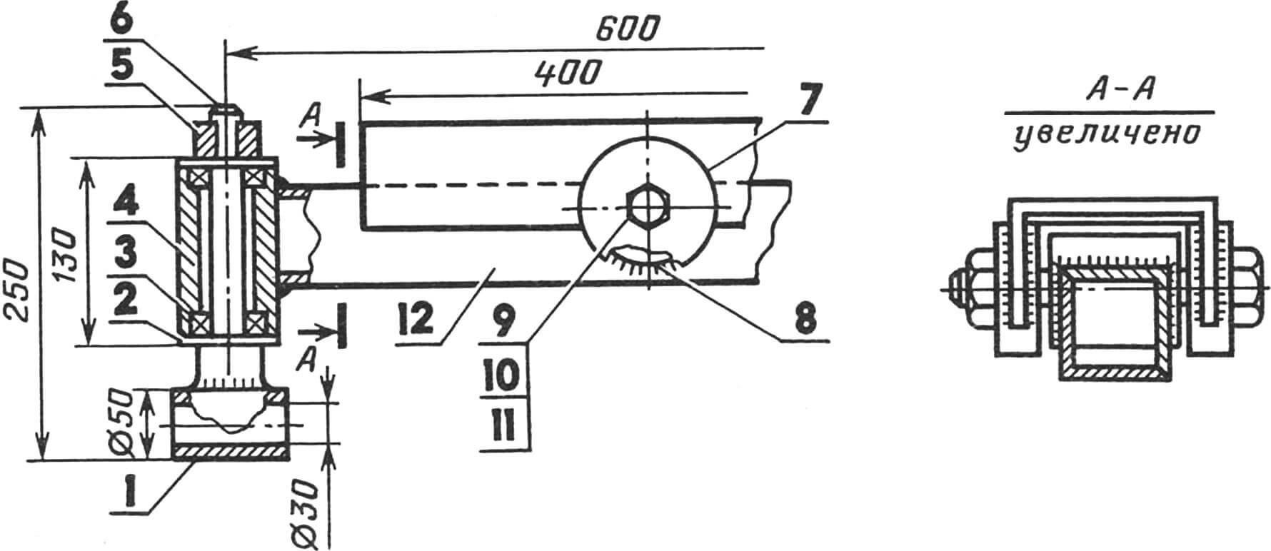
1 — front wheel axle bushing (Steel 45, 2 pcs.), 2 — cover of the bearing unit (St3, 2 pcs.), 3 — ball bearing 206 (4 pcs.), 4 — support-rotary rack bushing (from a 120-mm section of tube 70×14, 2 pcs.), 5 — steering trapeze arm (2 pcs.), 6 — pin Ø 30 mm with a splined end (from decommissioned agricultural machinery, 2 pcs.), 7 — cross member of the front axle frame bracket, 8 — unit of two bearings 2507 welded, 9 — axis-bolt M30, 10 — nut M30, 11 — Grover washer, 12 — front axle beam (from a section of square tube 65×5 or box-welded two steel angles No. 6.3).
The steering column is from the GAZ-21 “Volga” car. And a “ball” type handle from a forklift is installed on the steering wheel, making it easy to control the tractor. Moreover, even with just one hand.
The wheels are modified from old car wheels. They are made separate and have offset flanges. Such a wheel is more convenient for row crop cultivation. In addition, there is a real possibility of changing the track width depending on the work being done. The journal has written about the features of such constructions many times, so it is hardly advisable to dwell on them more here.
Pneumatic tires for the front wheels are from the C3A motor scooter, and for the rear (driving) wheels are from the MTZ-50 “Belarus” or MTZ-80 tractor. There is also the possibility of installing wheels with discs from GAZ-51, GAZ-53 trucks instead of the latter, which have a larger diameter and width. This allows increasing the track to 1350 mm, providing additional convenience when operating the mini-tractor in transport work.
In the magazine publications, it has already been noted that when choosing tire sizes, their diameter, and rim width, it is necessary to take into account the predominant type of work during the operation of the MT. And with this, of course, it is impossible not to agree. For tractors that are primarily intended for transport work, wheels with a rim size of 13-16″ are needed. And for plowing, those with an 18-24″ rim are required. After all, such tires can transmit greater traction force. Moreover, their rolling resistance is lower than that of small wheels. Hence, as they say, you need to dance to this tune.
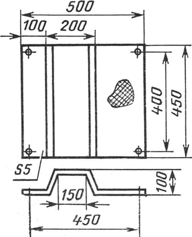
The fenders of our MT wheels, the mudguard, the seat, and the fuel tank are made as a single unit, which is very convenient for repair and operation. Because it is enough to loosen only 4 bolts on such a structure, disconnect the lifting linkage of the hitch frame, and there you go! The entire unit is easily removed from the tractor frame.
As for the brakes, they are separate. Each wheel has its own. This allowed creating additional advantages in the control of the MT. Especially when exiting the furrow during plowing.
Now a few words about the engine. It is taken from a motor scooter. Installed on a special plate with slots for chain tension. At the same time, the plate serves as a reinforcing element for the tractor frame.
The lining? It is made of a 1.5 mm thick steel sheet. Painting is done with durable automotive enamels of corresponding colors.
Proper attention should also be paid to the electrical equipment of the MT. Provide lighting in front and rear, turn signals, and a sound signal. Install indicator lamps on the instrument panel for neutral gear, high and low beam, battery charge, and brake operation indicator. In short, secure and improve the MT design so that working on it is never a burden for you.
It is also worth noting that the mini-tractor was conceived as a row-crop. Hence the unusual attachment of the rear axle – flush with the MT frame, allowing it to have good stability with a fairly decent (350 mm) ground clearance, and other design features.
Rest assured: such a mini-tractor simply cannot fail to impress.
MINI-TRACTOR TECHNICAL SPECIFICATIONS
Dimensions (with the hitch frame raised), mm 1900x1050x1350
Wheelbase, mm 1250
Rear axle track, mm 950
Ground clearance, mm 350
Weight (without trailer and mounted implements), g 400
Engine from C3A motor scooter
Kinematics features presence of a reverse-reducer
Maximum transport speed, km/h 30
Working speed during plowing, km/h 4
Maximum plowing depth, mm 300
N. KORCHAGIN, Leningrad region.
Recommend to read
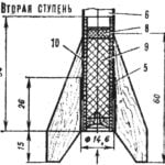 S1B — TWO RECORD STAGE
On the Fifth competition of the European championship miniature rocketmodel class S1B master of sports of the USSR Yury Soldatov brought its designer, the title of champion of Europe...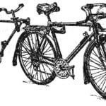 OF THE SATELLITES — TANDEM
Description a three-wheeled tandem, published in the journal (№3, 1979), I liked inherent in it the idea to tandem bike of the usual single, without making major changes to the original...
