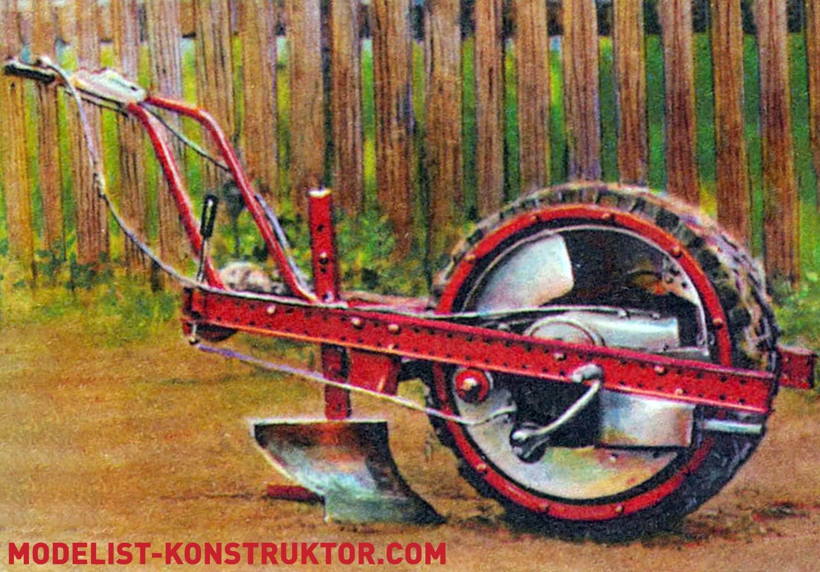
The proposed development is intended for plowing a small garden plot with a mini-plow, loosening the soil using a rotary tiller. Additionally, this motor block can be used for planting and hilling potatoes.
The “heart” of the mechanical assistant (power unit) is the engine from the “Electron” scooter with forced air cooling and handles for controlling the throttle valve and clutch (taken with cables from the same scooter). The engine’s driving sprocket is also “factory-made.”
The gear shift can be left as on a scooter, cable-operated. But it is more convenient to lead it directly to the frame’s longeron of the motor block. In this case, the gears will be switched using levers and rods.
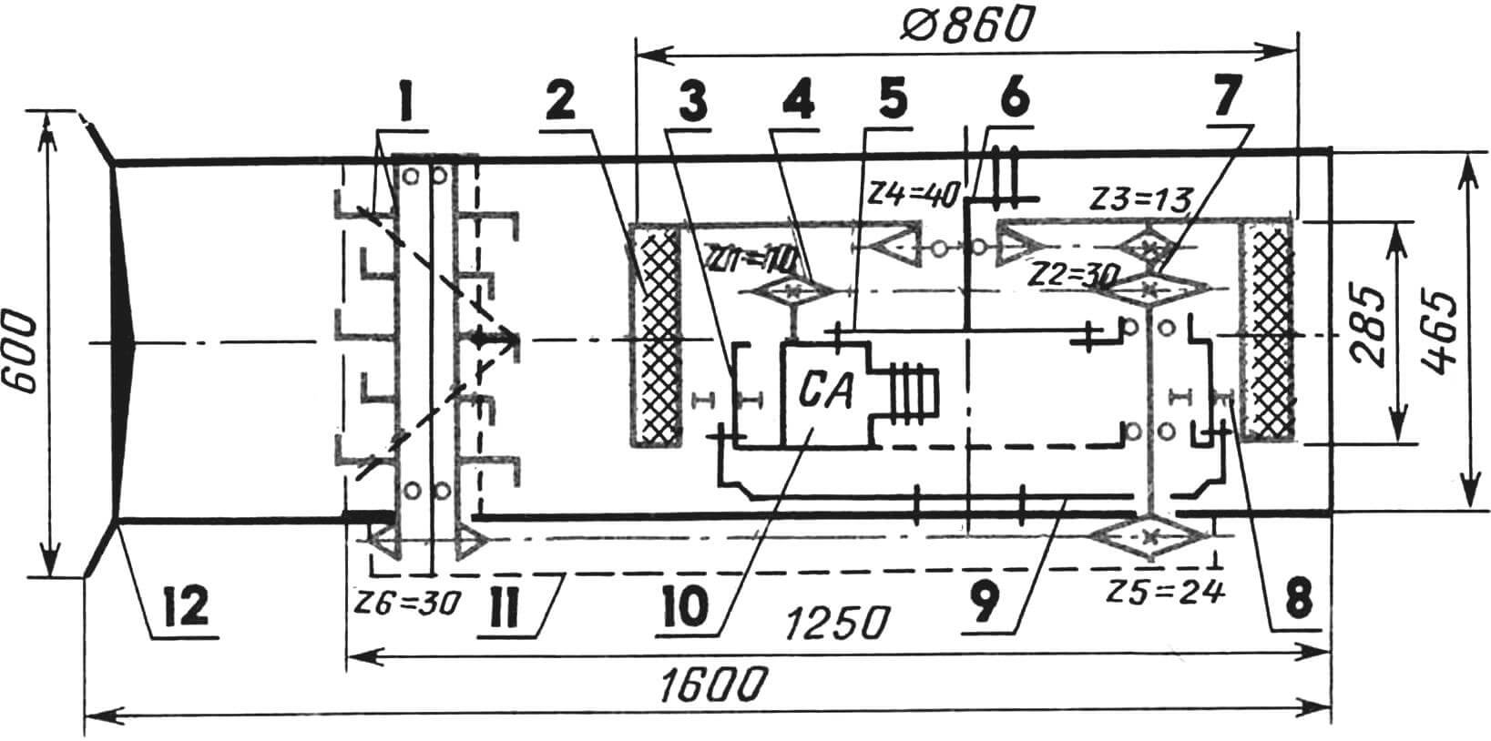
1 — rotary tiller (plow), 2 — working wheel, 3 — drum-type casing, 4 — output shaft of the power unit of the “Electron” scooter with the “factory” sprocket, 5 — transitional (intermediate) shaft disk-bracket, 6 — assembly of the inner ring of the ball bearing 80220 with protective washers and bolt-bracket, 7 — intermediate power take-off shaft, 8 — support roller (4 pcs.), 9 — bracket-bracket, 10 — power unit from the modified “Electron” scooter, 11 — casing-housing of the tiller, 12 — steering control.
The engine housing is attached in two places. Near the cylinder head — through a stand made of P-shaped metal strip (thickness 3…4 mm). And from the side of the driving sprocket, a special clamp is used. In addition, the engine case is securely fastened. It is installed on a rubber “pad.” It is advisable to cut recesses in the rubber “pad” in the configuration of the supporting part of the engine case. After installing the engine, attach the “pad” to the housing with self-tapping screws.
The engine is started using a modified kickstarter (the free end of its lever is slightly raised). For this purpose, an adapter is made, the mounting holes of which are shifted around the circumference by 45°. The torque from the driving sprocket of the engine is transmitted to the driven sprocket of the intermediate shaft using a chain drive (the chain is from the “Electron” scooter; however, it had to be shortened). Further, the rotation is transferred from the intermediate shaft to the driving sprocket of the motorplow.
Of course, you can change the gear ratio by using sprockets with a number of teeth different from those specified in the diagram. In this case, the speed will be a little less, but the pulling force of the motor block will increase. On the other end of the intermediate shaft, you can install a sprocket from the scooter (Z=24) for the rotation of the rotary tiller.
The exhaust pipe will have to be slightly modified by bending it at 90° so that the exhaust gases come out to the right along the course of the motorplow (into the muffler).
The housing is made of aluminum sheet (width 260 mm, thickness 2.5 mm), bent into a cylinder Ø 525 mm. “Ribs of rigidity” are installed on the end with a rivet (see figure) and a disk-bracket for attaching the intermediate shaft.
On the left, the disk of the sprocket Z=40 of the motorplow is attached to the housing. For this, 12 holes are drilled in the end of the cylinder, and M8 threads are cut into them. The ribs on the right side have a figured shape. Cutouts serve for the exhaust pipe of the muffler and the installation of the kickstarter lever. Along the circumference of the housing (on the right side along the course of the motorplow), 4 rectangular windows 20×50 mm are cut out for installing supporting rollers with axes. The rollers can be made of any material – bronze, brass, steel…
Inside the housing, not only the engine with an intermediate shaft is installed but also a fuel tank. Moreover—with an air cleaner. When refueling, it is necessary to unscrew the “rams” (at the top), remove the tank. After filling—put everything back in place and screw in the “rams”.
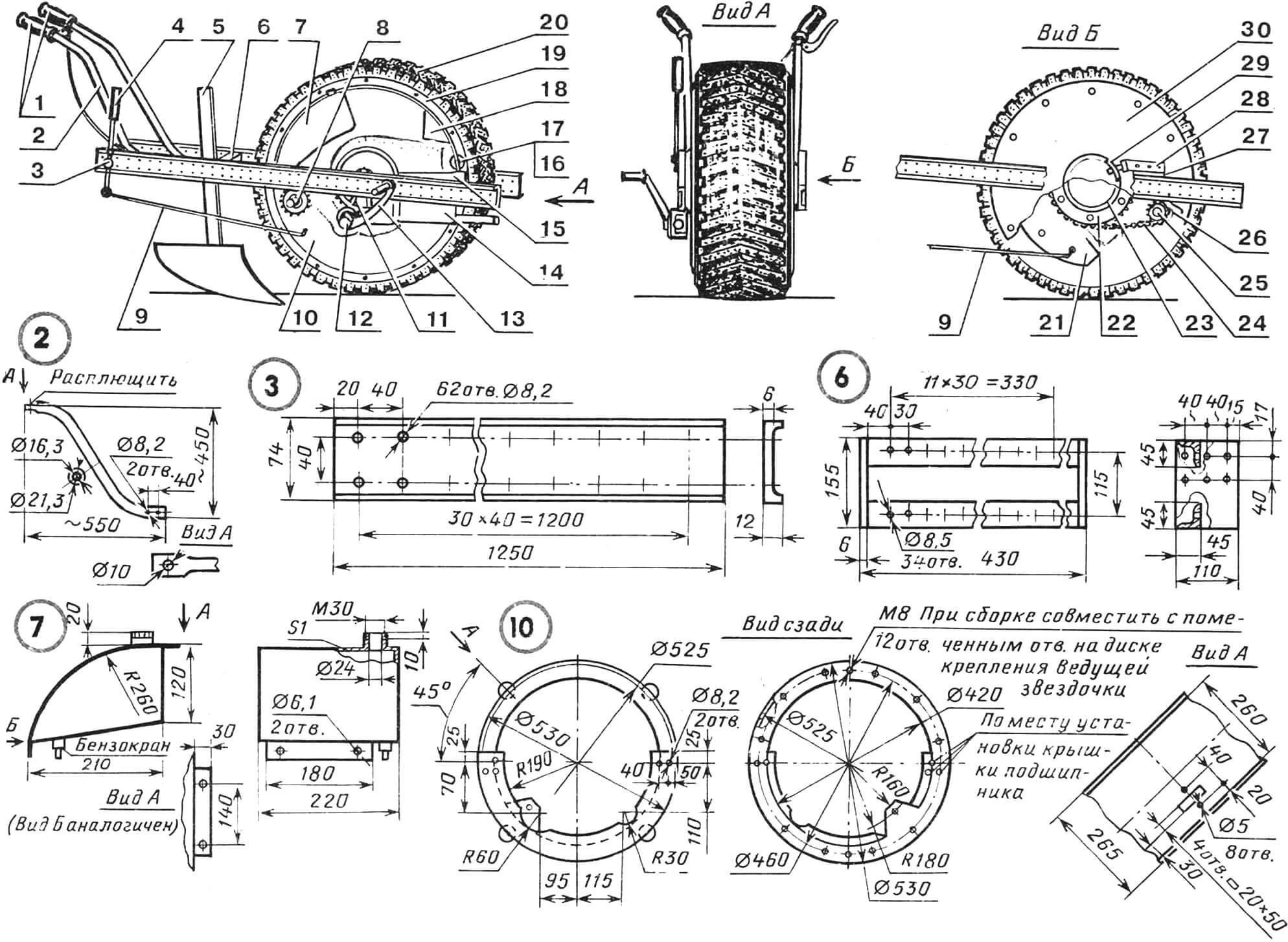
1 — handles for controlling the throttle valve and clutch (from the “Electron” scooter), 2 — control rod (from a section of 21.3×2.5 steel water-gas pipe, 2 pcs.), 3 — longeron of an H-shaped frame (from a section of milled steel channel, 2 pcs.), 4 — gear shift lever, 5 — horse plow with stepwise height-direction adjustment, 6 — crosspiece of the H-shaped frame (welded structure from sections of 6 mm St3 plate and 45×45 mm steel angle), 7 — fuel tank (from 0.5…1 mm galvanized iron), 8 — sprocket Z5=24 (fixed on the intermediate shaft with a prismatic key and M16 nut with a Grover washer), 9 — speed selector linkage (from a section of Ø 5 mm “katanka” chain), 10 — drum-type casing (from 2.5 mm sheet aluminum measuring 260×1650 mm, rolled into a ring, and attached with end-shaped ribs of stiffness — St3 with a thickness of 2.5 mm), 11 — power unit (from the “Electron” scooter) with forced air cooling, 12 — kickstarter adapter (St1), 13 — kickstarter lever, 14 — muffler, 15 — bracket-clamp (from 5 mm St3), 16 — roller (bronze, brass, etc., 4 pcs.), 17 — roller shaft (Steel 45, 4 pcs.), 18 — air cleaner (from 0.5…1 mm galvanized iron), 19 — wheel rim (from 2.5 mm St3 sheet), 20 — tread (from an old tire with removed sidewalls from the ZIL-130 truck), 21 — disk-bracket of the intermediate shaft (welded structure from 3 mm St3 and a section of 100×3 steel water-gas pipe), 22 — transition ring (from St3; fastens sprocket Z4=40 and the wheel disc to the outer ring of bearing 80220), 23 — ball bearing 80220 with protective washers, 24 — second stage of chain transmission Z3=13, Z4=40 (and PR — 12.7), 25 — intermediate transition shaft (Steel 45), 26 — first stage of chain transmission (Z1=10, Z2=30 and PR — 12.7), 27 — fastening plate (St3), 28 — bolt-bracket (welded structure from M16 bolt and a 124 mm section of St3 strip with a cross-section of 10×30 mm), 29 — “crescent” bracket (from St3, welded to the inner ring of bearing 80220), 30 — disc of the driving wheel (3 mm St3).
The air cleaner is filled with filtering material. A “well” for filling oil is also provided. This unit is attached to the housing using lugs and M6 bolts. It is connected to the carburetor with a rubber hose (from the scooter).
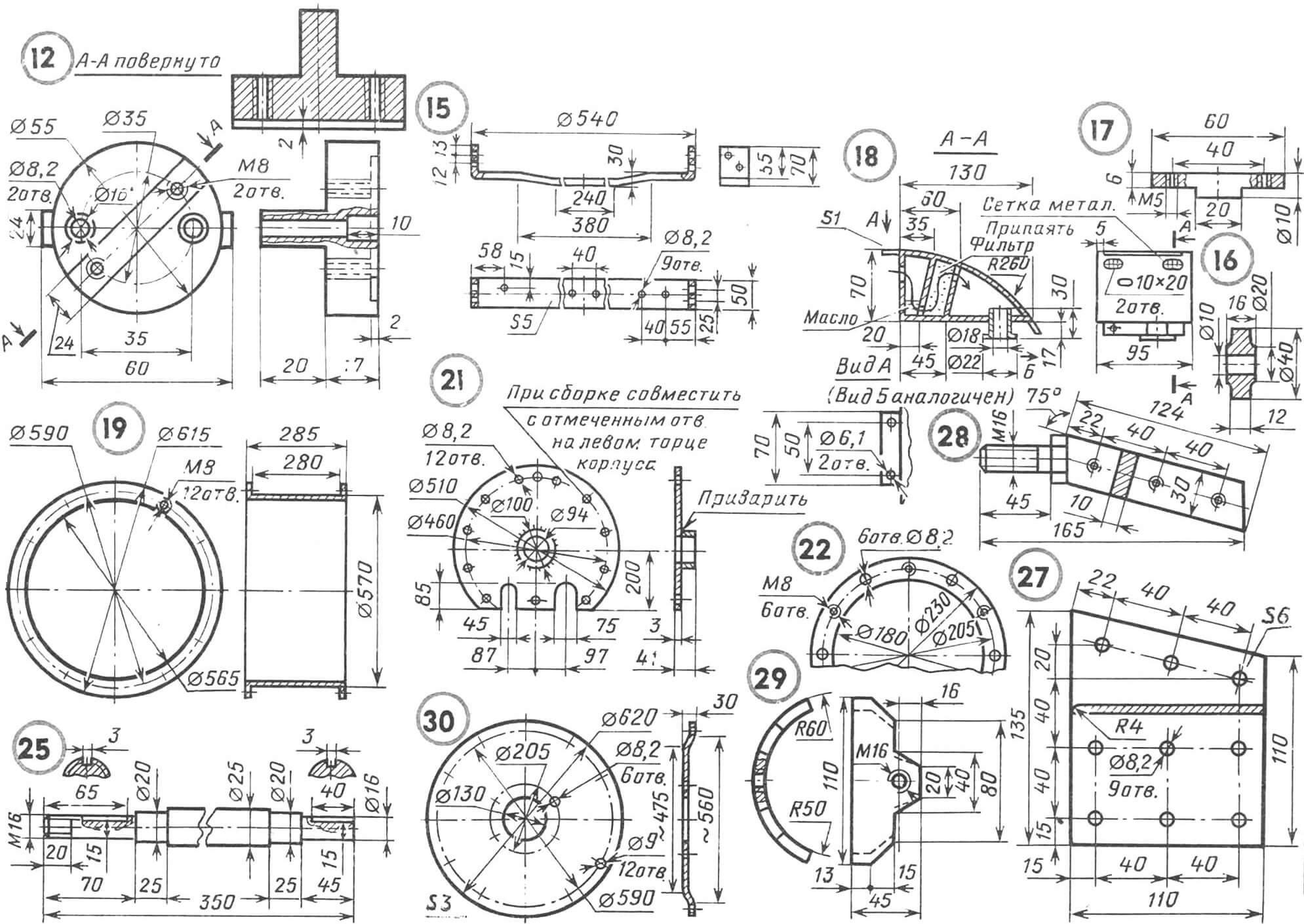
The disk-bracket of the intermediate shaft is made of 3 mm St3 sheet. Moreover, this part is cut from one side. The disk has two slots (75 mm and 45 mm wide) and a 94 mm hole in the center. Around the circumference with a diameter of 460 mm, twelve 8.2 mm holes are drilled. Here, a bushing-axle is welded from a 38 mm section of a 100×3 steel water-gas pipe. A ball bearing with an inner ring diameter of 100 mm (for example, from a tracked tractor) is installed on it.
The sprocket Z=40 is first drilled in the center and then reamed to the outer diameter of the bearing. After that, six M8 holes are made on it with a diameter of 205 mm.
To avoid permanently welding the sprocket to the bearing and to provide the possibility of quickly replacing it (just in case), a special ring had to be made (see figure), with a diameter of 205 mm — with 12 holes. Six of them with a diameter of 8.2 mm serve to attach the ring with the sprocket. The same number, but with M8 threads, are for a strong connection to the wheel disc. Moreover, the latter is preliminarily installed on the bearing with subsequent welding to it (possibly with “tack” welding). Then the “crescent” bracket is welded to the inner ring of the bearing. It will serve to attach the entire motor block structure to the left longeron.
After the “crescent” and the ring take their place (they are welded from the same end of the bearing), the assembly of the entire unit begins. In particular, the sprocket is installed on the bearing. It is fastened to the ring with bolts. Shims are placed between the ring and the sprocket. Then the bearing, together with the sprocket and the ring, is installed on the cylinder (see above), welded to the disc. Of course, it is best to do this using press-fitting. But (in an extreme case) you can “grab” it with welding.
The wheel disc is made of 3 mm St3. In diameter 590 mm, it has 1 2 holes for attaching to the wheel rim, which is bent from St3 sheet: this is a cylinder, on the ends of which there are ledges with twelve holes around the circumference of Ø 590 mm. On the reverse side of the ledge (opposite the holes), M8 nuts are welded.
Why are there such difficulties here? It’s because the ledges serve not only to attach the rim to the wheel disc but also act as ribs of stiffness. Moreover, they perform the functions of peculiar guides. For the tread, of course. So that it doesn’t “come off” the rim.
The tread is cut from an old tire (from the ZIL-130 car). Moreover, only the upper part of the latter is used, and the sidewalls are removed. This blank is wrapped around the wheel rim with subsequent tightening with a 6 mm wire clamp.
The design of the motorblock is such that it has power longerons on the sides (made of sections of channel), the ribs of which are milled to a thickness of 12 mm. The right one is attached with the help of a curved bracket-clamp, screwed to the body with four M8 bolts. Here, on the right side, is also the right housing of the intermediate shaft bearing. And the left longeron is pressed against the plate with a special bolt-bracket using the same bolts. Moreover, this bolt is screwed into the “crescent” and serves to create additional convenience during assembly.
To increase the rigidity of fixing the longerons, as well as the installation of the plow and other implements, a crosspiece located just behind the wheel is provided. It is welded from sections of steel angle with Ø 8.5 mm holes (every 30 mm). The latter serve for quickly rearranging the plow, changing the plowing width in one pass.
Adjustable-installation holes (but now Ø 8.2 mm) are also present on the longerons themselves (along their entire length, every 40 mm) — to change the distance from the wheel to the handlebars. The latter is taken from the “Electron” scooter. As for the steering brackets, they are made of a water-gas pipe 21.3×16.3.
The intermediate shaft is mounted on two bearings with an inner diameter of 20 mm. But you can also use bearings 205*. However, this will require a slight change in the diameter of the shaft. The bearings are installed in St3 housings, each having 3 M8 holes. Moreover, the one that is placed on the right side is attached to a curved bracket and the rib of the housing with M8 bolts. On the same right side of the intermediate shaft, a sprocket Z=24 is attached — for driving the earth tiller.
A few more remarks. As practice shows, when installing the engine, it is necessary to adjust it precisely immediately. It is understandable: after all, later access to it is somewhat difficult. As for the muffler, it is better to take it from some (including an old) scooter. But you can also make it yourself (see figure) from galvanized iron sheet with a thickness of 0.5…1 mm.
It is advisable to use a horse plow without any modifications. But a homemade earth tiller is used. It consists of a rotor on which legs are attached. Their length: 225 mm — “large” and 190 mm — “small”. The rotor is rigidly fixed on the axis. And the latter is on bearings. Their housings are “planted” on the tiller housing, which also serves as a casing, preventing the scattered soil from being thrown up and to the side of the plowman. The housing is attached to the crosspiece hinge-wise so that the tiller can be raised (lowered), thereby adjusting the depth of cultivation.
The rotor can be made from a section of steel pipe 195×3, to which knives 40 mm wide and 4 mm thick are welded each. There are a total of 20 knives in the design.
Finally, the last one. The gear ratio of the sprockets on the intermediate shaft is such that the rotational speed of the tiller rotor should be higher than the rotational speed of the drive wheel.
Technical Characteristics of the Motor Assistant
Dimensions, mm:
in working condition – 600x1600x880
in transport – 465x1250x860
Weight without ballast and hitched (attached) implements, kg – 80
Power unit from the “Electron” scooter (modified)
Engine power, hp – 3.5
Soil processing speed, km/h:
with a tiller – 5
with a plow – 3
Transport speed, km/h – 35
A. Zotov, Cheboksary
Recommend to read
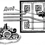 BY “DIMLY”
As a rule, in all our homes — three-wire system on the chandeliers, combined with the series switches, providing three options of illumination. For patipanno chandeliers — two, three and... MODE SPOT WELDING
I made welding machine is a well-proven in practice a modernized version of the device description and drawings of which are published in the journal "modelist-Konstruktor" No. 3, 1966....
