 Design truck for paraglider was preceded by just the fascination of paragliding, which did not come at once. First flew airplanes (and flight certificate), gliders. But one day, fly a paraglider, got into it seriously. I think it is comparable to swimming to sailing. Only even better.
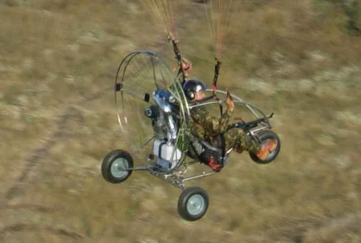
First, like most parable-Aristov, used for takeoff and landing conventional three-wheeled cart. Not going to say much about all her faults (they are known to the pilots para-glider). But the most unpleasant of them tipping forward and sideways with insufficient management skills dome on takeoff and landing. But for experienced paraglider on a truck is not immune from stalling—for example, when a side gust of wind. And this is very dangerous because the rollover more likely, the higher the speed, i.e. during takeoff and especially during landing.
In the end, decided to make for himself a four-wheeled cart. And when thinking this, then came up with other ideas—for example: why not to use the same cart for movement to the airfield and back, especially since touchdown may occur far enough from the takeoff.
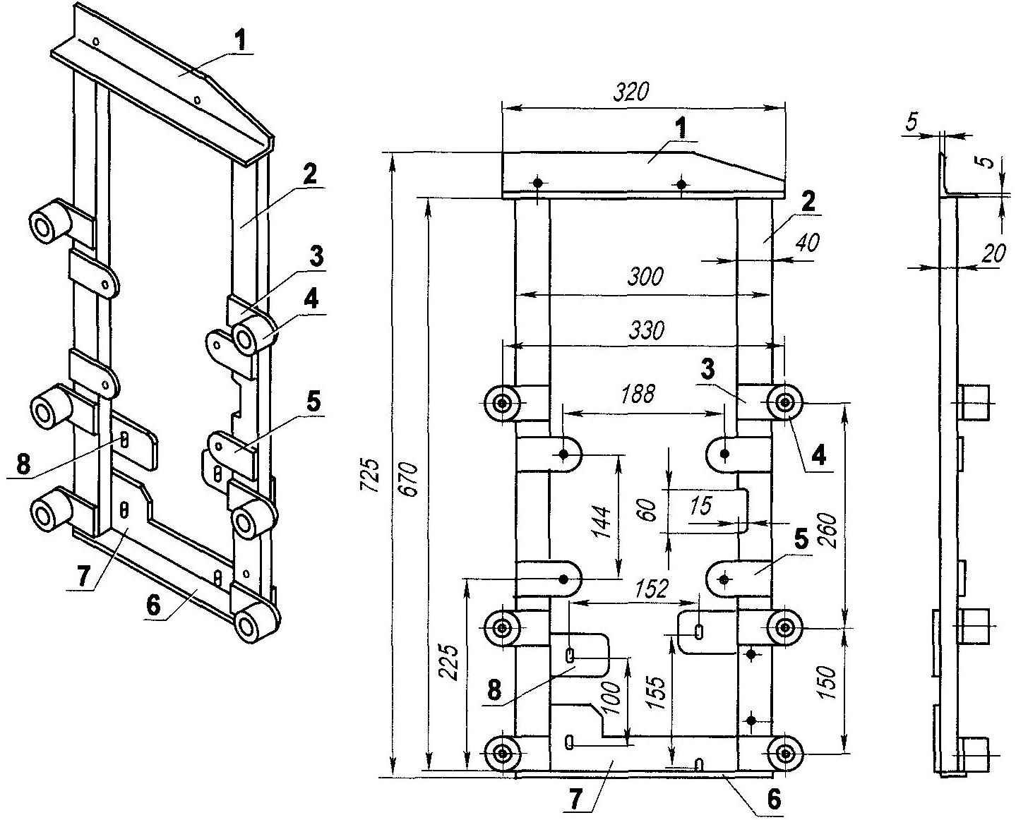
All units and mechanisms: paramotor, controls them and the cart are based on the spatial frame-the frame. The base of the frame—two identical closed contour element, shaped as a rectangular trapezoid. Although the contours on the location and functional purpose it can be divided into longitudinal (lower horizontal part), stand (vertical back and sloping front) and the crossbar (top), they are all made as one piece of thin-wall steel (s = 2 mm) tube outer diameter of 28 mm.
Here I note that the decision to make a frame of thin-walled steel tubes, not of duralumin, adopted because welding is much easier, and the loss in weight is insignificant. Moreover, in case of failure of the steel frame can be brewed in any nearest workshop, but argon welding for dural details have yet to be found.
Elements are linked together in several places with crossbars, made of steel pipes with a diameter of 20 mm (wall thickness 2 mm). Closed items at the same time serve and arcs security.
The spars are welded a variety of brackets, lugs and lugs for fixing on the frame suspension front and rear wheels, arm-control lever, seat.
The attachment points of the motor power unit and fencing welded to the upright elements of the frame, and the gussets between the uprights and connecting them with cross members.
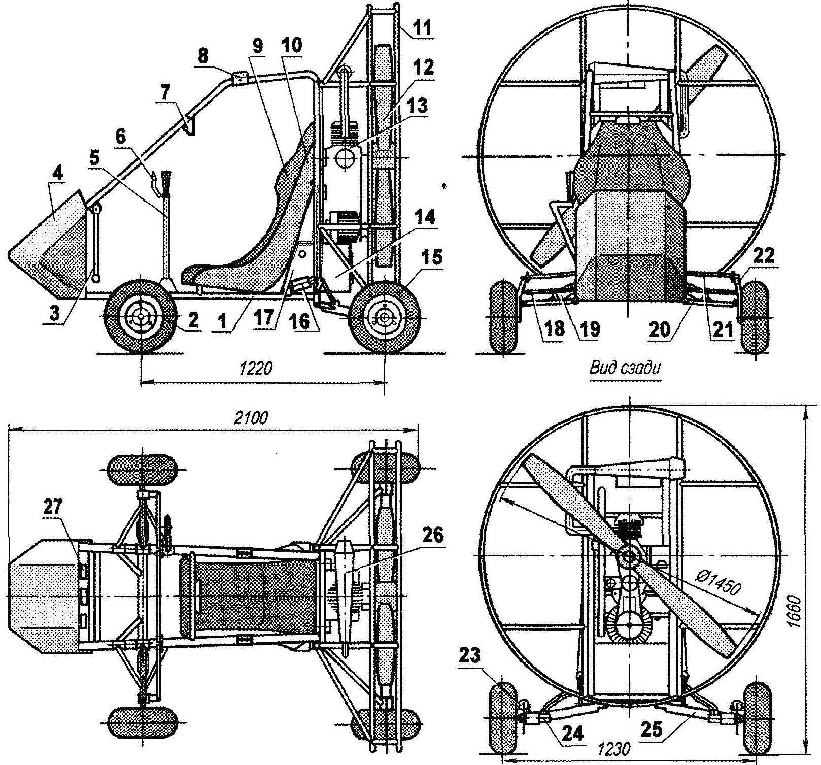
Four-wheeled paramotor truck:
1 — power frame;
2—front driven wheel (map, 2);
3—the control pedal front wheels (2 PCs.);
4—fairing (fiberglass epoxy binder, s3);
5 —crank-lever;
6—control knob “gas”;
7—rear view mirror;
8 — bracket gear sling chute (2 PCs.);
9— seat;
10—the cradle;
11 — fencing of the screw;
12 — screw;
13—power unit UP = 27 HP);
14—fuel tank (V — 15 l);
15—rear wheel (map, 2);
16—rear shock absorber (gas Cycling, 2 PCs.);
17—oil tank (V = 8 l);
18—steering link (2 PCs.);
19—front shock absorber (2 PCs.);
20 — lower arm front suspension (2 PCs.);
21 —upper front control arm (2 PCs.);
22—steering knuckle (2 PCs.);
23—brake mechanism (2 PCs.);
24 — motor (V = 20 cm3, 2);
25—arm rear suspension (2 PCs.);
26 — muffler;
27—dashboard.
Several Ushkov welded in the bottom of the front sloping bar racks for mounting plate made of duralumin 1-mm sheet (later replaced flap laminated fiberglass fairing). Polik fabricated from 3 mm corrugated dural sheet.
I’ll tell you that during operation the truck is upgraded. So, in addition to the fairing was replaced the handlebars on the handle—like aircraft. Was reinforced front suspension made other changes. But more on that later, in the course of the description of the structure.
Front-wheel—driven, rear—leading driven by hydraulic motors. All wheel suspension—independent. At the rear—single lever on the oblique (longitudinal-transverse) levers, like those that were on “the Cossacks” or if you want — a BMW. The front suspension was initially too single lever (with wishbones), but later it was necessary to strengthen another the upper arm and make it a parallelogram-type linkage. The rear and the front lower wishbone is made of the same steel pipe as the cross member and the front upper tube diameter of 16 mm, and the configuration of it is the same as the bottom—only mirrored. All hangers installed bike gas shock absorbers (first was a spring-hydraulic from moped). Move levers and both pendants are about the same—about 150 mm. And the rear shock absorber is placed outside of the suspension (spar) and is connected with it through the cravings and a rocking chair.
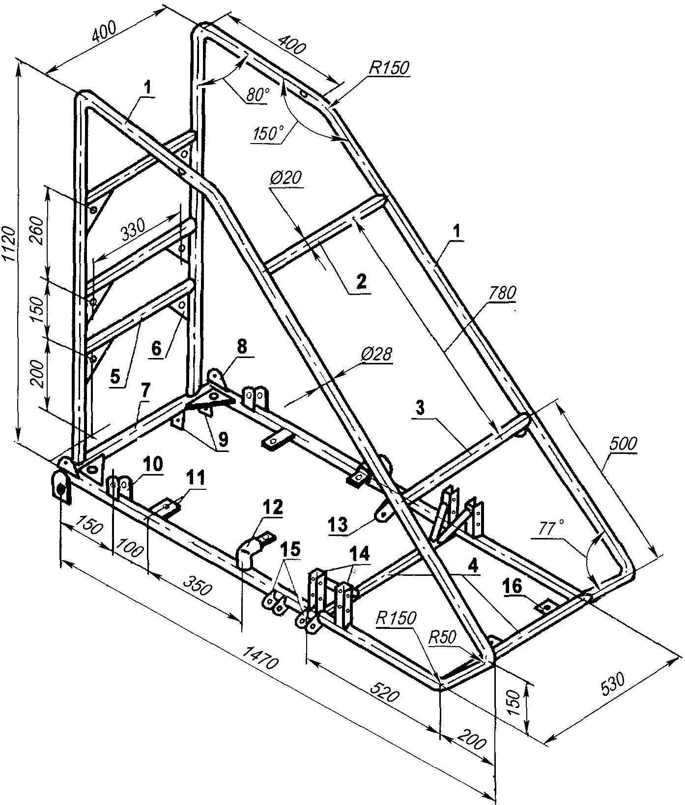
The frame of the cart (children, POS. 1 and 7 is made of a steel pipe 28×2; POS.2,3,4,5—pipe 20×2):
1 — frame left-right mirrored;
2 — jumper rear view mirrors;
3 — jumper the dashboard;
4 — jumper mounting floor;
5 — jumper mounts engine mounts (3 PCs.);
6 — Klondike solitaire-the mounting bracket of the engine mounts and fuel tanks (8 EA.);
7 — cross-member;
8 — eyelet rocking chair (2 PCs.);
9 — lugs mounting rear suspension arm (2 pairs)
10 — lugs securing the rear shock absorber (2 pairs)
11 — the lugs securing the rear portion of the seat and the floor;
12 — mounting brackets the front of the seat;
13 — lug suspension pedal arm (2 PCs.);
14 — brackets-mounts the upper arm of the front suspension with struts (2 pairs)
15 — ears attaching the lower front control arm (4 pairs);
16 — lug floor mounting (2 pieces).
The front suspension is shifted back from the nose of the car, as if reducing the wheelbase, that is not entirely rational when riding on the ground. However, in the air, due to the shift of the center of air resistance is assumed reduction of yaw in flight.
Rear wheel is also, as far as was possible, made ago, their axes are almost in the plane of the screw. First, this was done based on convenience of layout—improved weight distribution (almost 50×50%); secondly, increased stability in flight due to the shift of the center of air resistance back, in third place—less chance for “turtle” (tilting back) at the start.
Engine mount (material details steel 30KHGSA):
1 — the upper crossmember (stamped area 50x50x5);
2—front (strip 40×20,2);
3 —bracket-eyelet silent-block (sheet s5,6 PCs.);
4—silent-block (6 PCs.);
5 — bracket-lug mounting engine (sheet s5, 4 PCs.);
6, the lower cross member (sheet s5);
7 — vertical shelf bracket (sheet s5);
8 — bracket-eyelet pump (steel, sheet s5, 2 PCs.).
Control of the front wheels—mixed type, or rather duplicated— manual and pedal. The necessity of their turning feet revealed at the first take-offs and landings, when the hands were more necessary to control the parachute.
Foot front wheel drive is pedal using flexible steel wires located under the fairing. Here is the same and the brake pedal.
Manual control is first carried out from the helm of the motorcycle type via hard thrust. Subsequently, the steering wheel was replaced with a grip-lever—similar to what are on the aircraft, but only mounted on the right side of the truck. Thus I replaced the upper wishbones and steering knuckles on the front wheels.
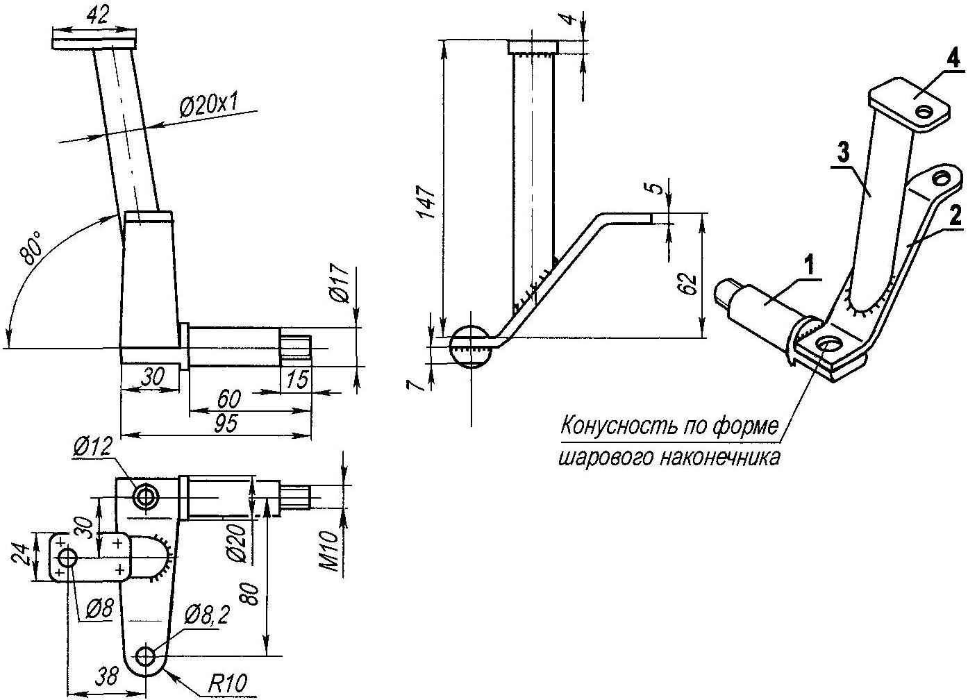
Steering knuckle and axle front wheel:
1—axis (steel, circle 20);
2—lever (steel, sheet s5);
3 — front (steel 30KHGSA, steel 20×1);
4—eyelet upper front control arm (steel, sheet s4).
On the steering wheel (and later on the handle-lever) are all controls-rotor installation.
Now about the main—on-rotor, and more specifically, about the power plant, because the engine works not only on the screw, but on a truck wheel through a hydrostatic transmission.
Engine—МZ34 canadian company Zanzaterra power 27 HP at 6300 rpm, two-stroke, air-cooled that runs on gasoline AI-95 with the addition of 2.5% of the engine oil. It is supplemented with a switch and a PTO. Now the torque with its output shaft is transmitted via a belt transmission or the screw, or a hydraulic pump. Switching is performed while the engine is stopped. The screw rotation is transmitted with the 16-stream of the belt over the appropriate pulleys with a gear ratio i = 2,38. On the input shaft of the hydraulic pump the rotation is transmitted also via V-belt. Only the number of streams at the belt (and pulleys) at 14, and the gear ratio was 1.74.
Radial-piston hydraulic pump manufacturing American company Jaton creates pressure 137 bar (about the same ATM) and pumps the oil through the hoses to the hydraulic motors (the company Chan Lynn with a volume of 20 cm3 each), which are mounted on shafts hubs rear wheels. To ensure that the hydraulic fluid below power plant, near 15-litre fuel tank mounted oil tank, capacity 8 l, Both are attached to the rear lower cross member with steel tapes.
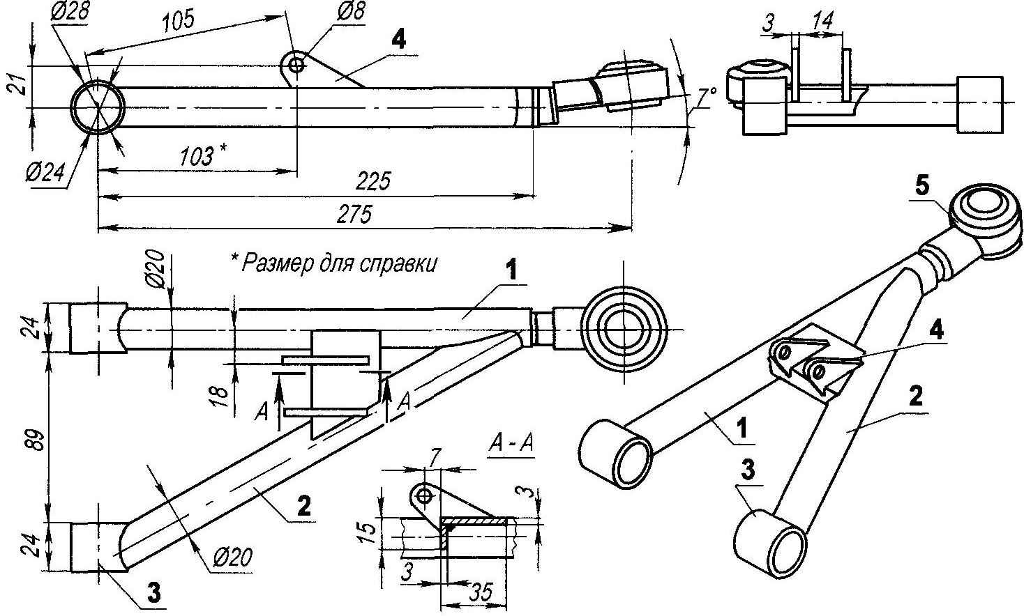
Lower left front control arm (right—mirrored; the material of the upper wishbone tube 16×1):
1 —main core (steel 30KHGSA, steel 20x 1);
2—brace (pipe 20×1);
3—bushing;
4 — the eye (steel, sheet s4);
5—tip (VAZ-2108).
Consider the use of a hydraulic drive wheels of the truck more rational and justified than a massive mechanical transmission, although the efficiency of the “hydraulics” is much lower transmitted its power to the rear wheels is about 15 HP, the Use of hydraulic motors to drive the wheels when moving on the ground is justified by the fact that the screw raises a lot of dust.
 First flight tests (takeoffs and landings) confirmed assumptions about robust stability of the truck made according to the four-wheeled arrangement, even in case of unsuccessful UPS and oblique touch land with “pendulum”. Long travel suspension with gas-filled shock absorbers provide a soft landing and smooth ride when you run. In many ways, this contributed to the wheels from the mini-buggy external tyre diameter of 350 mm and a width of 200 mm (boarding tyre size KB the tyre pressure is 1 ATM. or 0.1 MPa).
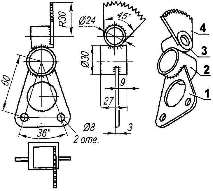
Rocking lever steering:
1 —bracket (steel, sheet s3);
2—bushing bracket (tube Ø30×2);
3 — bushing ratchet (tube Ø24×2);
4—ratchet (from the flywheel kick-starter scooter).
Air paramotor propeller with a diameter of 1450 mm increments of 500 mm (first was a wooden, now—GRP) provides paragliding at speeds up to 100 km/h. Enclosure of the screw— staff acquired together with the rotor installation.
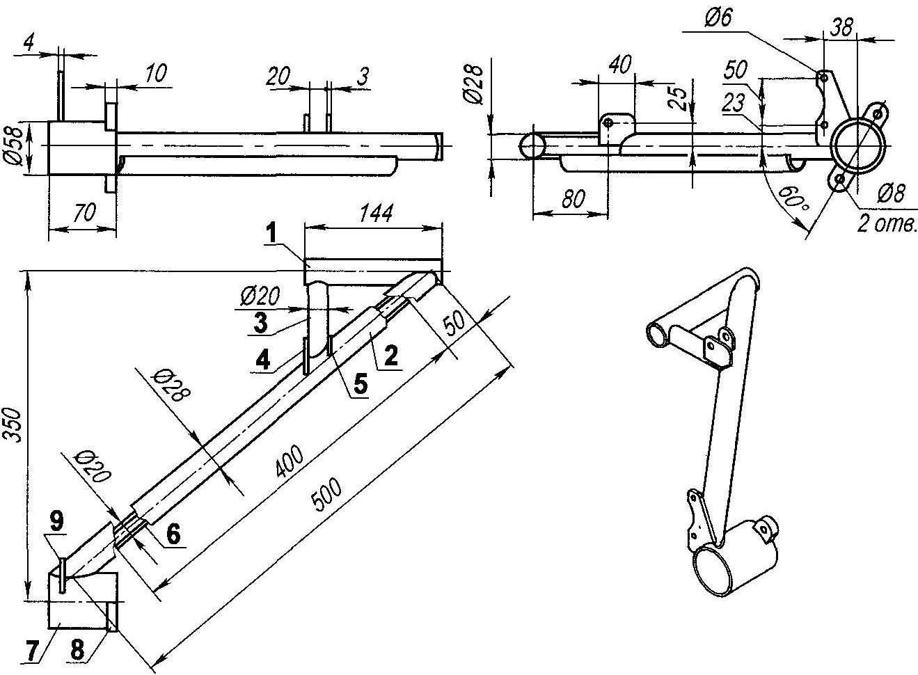
The left lever of the rear suspension (RH—mirror; material—steel 30KHGSA):
1 — bushing roller lever (pipe 28×2);
2 — the lever (tube 28×2);
3 — brace (pipe 20×2);
4 — a large eyelet thrust attenuator (sheet s);
5 — a small eyelet attachment of shock absorber (steel sheet s);
6 — booster in the arm (longitudinal half pipe 20×2);
7 — Bush of the hydraulic motor (pipe 58×2);
8 — eyelet hydraulic motor (sheet s10, 2 PCs.);
9 — the mounting bracket of the brake caliper (sheet s4).
The organs of the system starting the engine: battery and relays it is charging; a relay and a push button starter, ignition key (vykluchateli the “masses”) are located in the small box to the left of the pilot’s seat. By the way, the seat is anatomical, with shoulder pristezhnye belts.
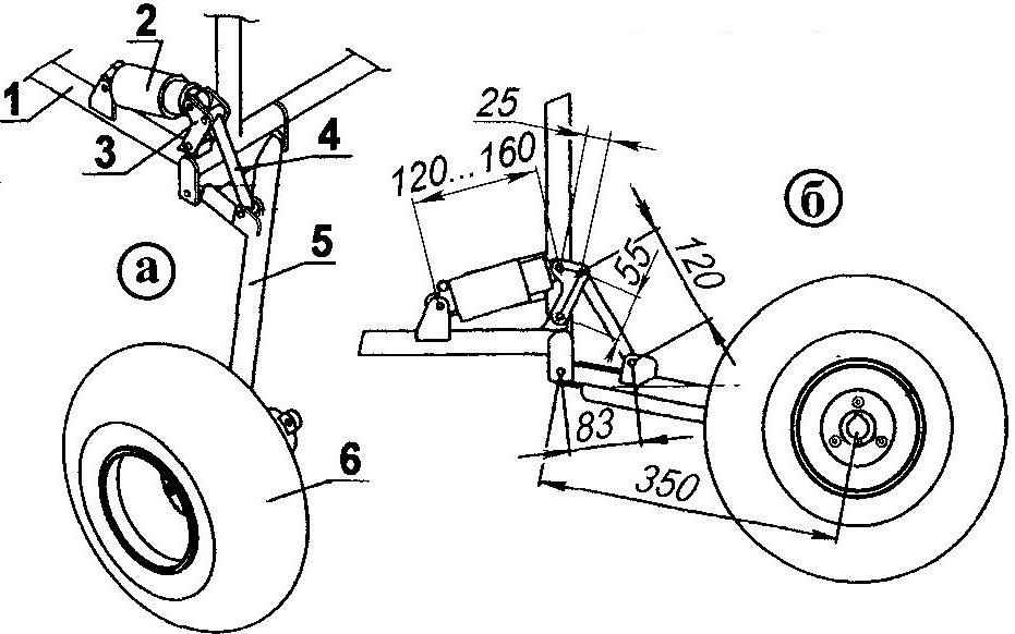
Suspension rear left wheel with a progressive scheme of depreciation (a—isometric; b—side view):
1 — frame;
2 — attenuator;
3 — rocking chair;
4 — thrust;
5 — arm;
6 — wheel.
As mentioned previously, the controls of the truck except brake and system of engine start-up, focused on the arm-control lever. It is mounted on the right side of the pilot’s seat removable handle motor control. Moving the lever left and right is turn of the front wheels, and forward and backward from the neutral position — turn on respectively the front or the back of the truck. Further movement of the lever increases the oil flow to the hydraulic motors and thereby the speed of movement of the trolley.
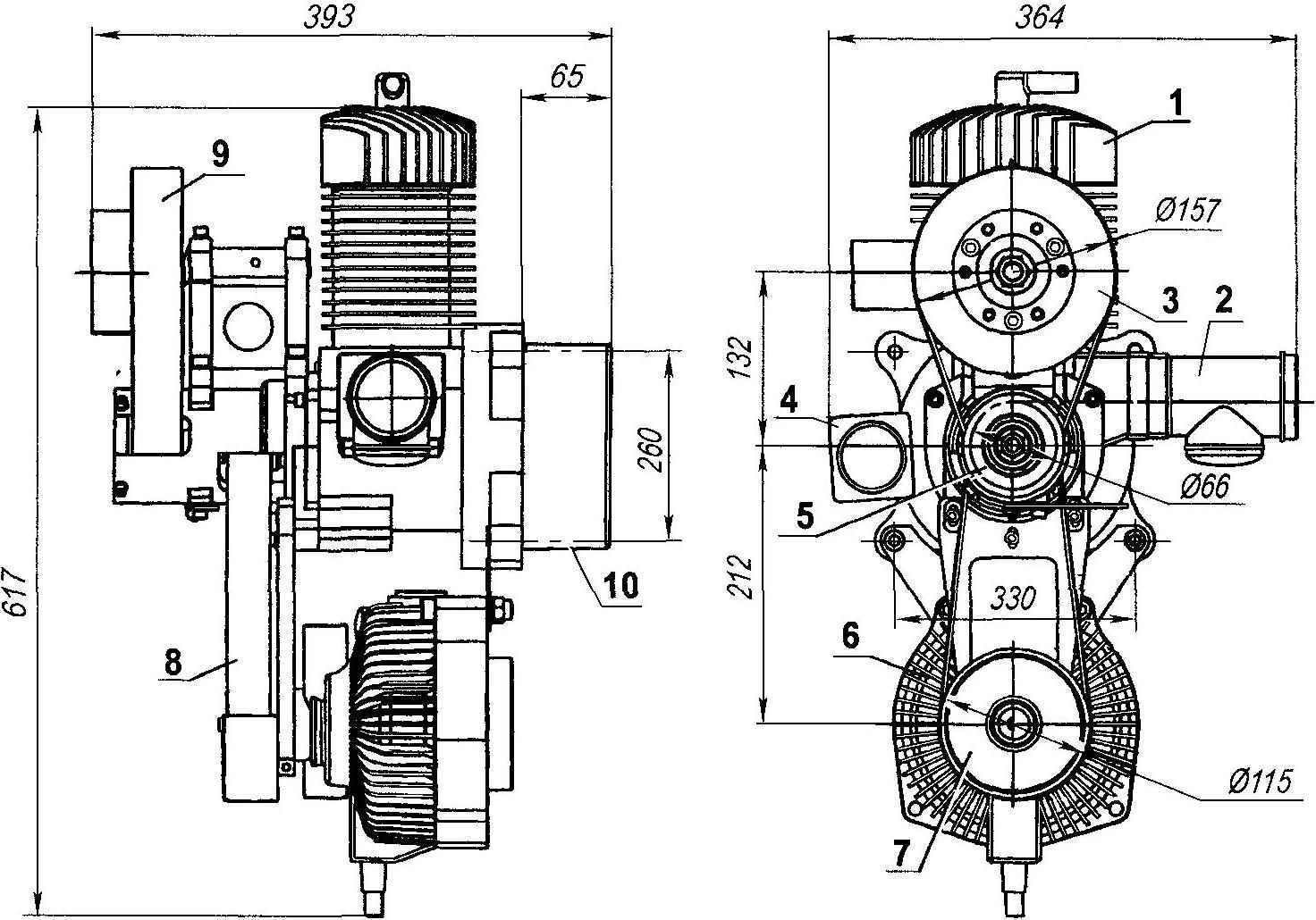
Powerplant:
1 —the cylinder of the engine;
2—silencer;
3—the slave (drive) pulley shaft screw;
4—switch: screw—cylinder (wheel);
5 — drive pulley shaft of the engine;
6—the hydraulic pump;
7—slave (drive) pulley shaft of the pump;
8—the drive belt of the pump;
9—belt drive shaft of the propeller;
10—the crankcase.
Removable handle is a lever “gas” and the stop button of the engine. In flight, the curved lever trolley is fixed in the neutral position, and the handle is the pilot holds in one hand in a comfortable position.
The original version of the truck did not have control of the devices—they were added later along with a fairing (instead of flap) on the front panel. Control devices three. The first right is the fuel gauge in the tank, mid — altitude, and extreme left—the device monitoring engine: the cylinder head temperature, exhaust gas temperature.
Atideo:
Recommend to read
 BRUSH FOR POLISHING
It will be a good helper in all cases where any surface is necessary to impart roughness. For example, to glue ceramic tiles on painted with oil paint the wall. You take a plate,... Play structures in the yard
How can you equip a children's playground in the yard? You can simply install a sandbox, a slide, or carve figures of fairy-tale and cartoon characters from logs. But that is not the best...
