On the output shaft of the reverse gear set sprocket (z =13) drives the front axle and the fork of the propeller shaft. The second fork of the propeller shaft through intermediate shaft is connected with a flexible coupling, which is the compensator axial movement of the gimbal in the “fracture” of the frame on turns and damping shock oscillations induced in the transmission the Second the coupling end is mounted on the splines of the shaft along with the sprocket (z =13) drive the rear axle.
Kinematic scheme of transmission Rover L. Antonova:
1—front axle;
2—differential (from the car “Moskvich”);
3—star differential (z = 40);
4—chain drive of the front axle;
5—supporting roller;
6—sprocket of the output shaft (z = 16);
7 primary sprocket gearbox; (z = 31);
8—asterisk PTO shaft reverse gear (z = 13);
9—brake drum, transmission brake;
10—gear drive range (m = 3, z = 23);
11 —gear forward (m=3, z= 18);
12—drive chain rear axle;
13—the rear axle;
14—rear axle shaft;
15—sprocket of the propeller shaft (z=13);
16—intermediate gear of the reverse gear (m = 3, z = 18);
17 — sprocket output shaft reverse gear (z=13).
The driveshaft is inside the hole sizes 100×100 mm hinge rotation. The axis of rotation of the propeller shaft must strictly coincide with the point formed by the intersection of the vertical axis of hinge rotation, and the horizontal axis “swing” bridges relative to each other. This operation is rather complicated, but it can be slightly simplified by replacing in the Assembly of the cardan shaft with clutch for a mandrel diameter of 50 mm, with two lateral holes with a diameter of 20+0.1 mm (vertical axis of hinge rotation) and a diameter of 15 mm (the axis of swing bridges) that are located at an angle of 90° relative to each other, strictly on the axis of rotation of the mandrel at the point of fracture of the propeller shaft. On this mandrel and is going reverse gear and shaft bearing housing and bracket. Installing in the rear fork of the cardan shaft round rod with a diameter of 15 mm along the axis of the swing bridges, and collecting the hinge rotation on the rod 20 mm in diameter, passing in the hole of the mandrel, necessary to secure the welding reverse gear on the front fork hinge rotation, and the bracket welded to the pipe frame of the rear axle via an intermediate pad adapter.
The reverse gear of the vehicle:
1 —sprocket (z =31);
2—a flange of fastening of brake pads;
3—bolt M8 with nut and washer;
4—gear input shaft (m=3,z=18);
5—shift fork reverse gear;
6—washer;
7—the primary splined shaft;
8—intermediate gear (m=13,z=18);
9—bushing intermediate gear;
10—shaft intermediate gear;
11 —output shaft reverse gear;
12—gear (m=3, z=18);
13—gear (m=3, z=23);
14—sprocket (z=13);
15—bearing 1203;
16—sprocket (z=13);
17 shift shaft reverse;
18—bearing 203;
19—body;
20 bearing 205;
21 —oil seal 46x32x10 mm;
22—brake lever;
23 —brake Cam;
24—mounting the gearbox.
Now it is necessary to replace the mandrel propeller shaft with clutch, and the rod diameter 20 mm — two axle and check the smoothness of the propeller shaft at various angles of rotation and angles of the swing bridges. Reverse gear created by L. Antonovym yourself. His body is made of two parts. For a mutual docking and alignment on the gear cover is undercut, and in its own housing — ledge.
The work begins with grinding on a lathe the cover and the housing with a fine outer dimensions. Inside is first, a preliminary hole, so that the thickness of the end walls was 12… 15 mm. This thickness is necessary in order to make the case less “led” by welding. Further, the lid and body are connected by bolts with thread M8, then on the front surface of the housing and mark the axis of the shafts and drill the holes for the bearing of the shift shaft and the reverse shaft intermediate the reverse gear. This operation is best done on a milling machine with the reconciliation center-to-center distances on the limbs of the machine.
Bearing, retainer shift shaft reverse, flange brake pad mounting parts gearbox to the frame are welded to the case and the gear cover. After welding the bolts M8 securing the cover to the body turning away and processed to predetermined sizes of the internal part of the body. The final thickness of the end walls should be 4… 5 mm — that is enough. In convenient parts of the body cut threaded holes and are provided with threaded tubes the same — they needed to change the oil in the gearbox.
The gears and shafts of the gearbox are made of steel grade 40X, with subsequent heat treatment.
The frame of the vehicle consists of two hinge-connected but semi-frames, each assembled from steel pipe of diameter 60×3,5 mm, welded with the corresponding bridge. On the frame there are four split nodes: two of them provide the tension of the chain transmission, the third is the hinge rotation and the fourth joint of the swing bridges.
The front axle of the vehicle (the main view of the planned projection):
1 —star;
2—bushing (pipe d20x1,5 mm);
3—stud M10;
4—the rib;
5—frame;
6—bearing housing;
7—bolts bearing housing M8;
8—the bearing 207;
9—the differential case;
10—bushing coupling rod (mounted on plug lap joint);
11—struts;
12—stocking the half-axis (tube d60x1,5 mm);
13—bushing;
14—oil seal;
15—bearing housing;
16—axis;
17—bolt М10х 1.
Hinge turn is collected using the welding of parts cut from steel sheet in the thickness 6…8 mm. Plugs of the hinge are assembled with axles with a diameter of 20 mm, passed through the bearings n 204.
To provide enhanced rigidity of the rear half frames, the rear axle is additionally fixed relative to the longitudinal pipe articulated two struts of tubes diameter 20×1,5 mm. On the front frame is fixed by welding closed circuit, assembled from pipes with a diameter 40×1. 5 mm and repeating the shape of the cab floor
The front and rear axles of the vehicle is homemade. Bearing housing, differential and shortened axle from the car “Moskvich”. The differential housing closed metal housing. The driveshaft fit with the bushing (hot landing), fixed on the elements of the axle plug lap joint.
Rover engine — motorized FDD. The location is on reverse gear and turn hinge on the front frame, and is the engine on the machine with the cylinder ago. The tension of the chain connecting the output sprocket of the engine sprocket with reverse-reducer, — by means of linings. In any case, among the package of pads used a couple of rubber with a thickness of 6 mm, designed to isolate the frame from vibrations of the motor.
The engine is started using the kick-starter from the cockpit. To improve starting during winter, the carburetor is equipped with an additional choke.
To prevent winter icing of the carburetor and the cabin Windows to Vozduhoflotsky carb and to the windshield via the corrugated hose with a diameter of 44 mm is fed warm air from the engine cooling system.
Ignition system and electrical power is supplied from the generator, borrowed from the motor scooter “Electron”. Provided and installation of magneto — in case of emergency failure of the primary ignition system.
In the right engine cover coaxially to the axle of the crankshaft is made of undercut, in which the four M6 bolts fixed adapter flange. The latter has three threaded holes M5 for fixing the base of the generator. Right axle crankshaft machined under the seat of the flywheel motor scooter “Electron”. Magneto is installed on the left side of the engine.
Hinge rotation:
1—bracing of the rear axle (tube diameter 20×1. 5 mm);
2—bolt M10;
3—bushing;
4—clamp;
5 — chain drive reverse gear;
6—chain drive of the front axle;
7—mechanism for adjusting the tension of the chain;
8—rubber gasket;
9—a pipe of rectangular section for fastening of the engine;
10—cover;
12—bushing chain tension;
13—the axis of hinge rotation;
14—spacer washer;
15 — plug rear axle;
16—bearing housing;
17—tube frames;
20—Bush;
21—sprocket (z=13);
22—bracket steering rod;
23— Kardan;
24 — shaft;
25 — fork gimbal;
26—coupling half;
27—finger;
28—bolt M6;
29—bearing No. 204;
30—bearing housing;
31—bearing No. 205;
32—oil seal;
33—cover;
34 spline shaft;
35—sprocket (z=13);
36 — coupling half;
37—brace sleeves;
38—fork of the front axle;
39—bolt M8;
40—the elastic coupling;
41—limiter tilting axle;
42—bracket (rectangular tube 60×30 mm);
43 platform;
44 chain drive rear axle.
Motor closed casing of duralumin sheet thickness of 1 mm.
The machine showed that the engine power is enough for driving on the roads, crust and ice with speeds up to 60 km/h, and in deep loose snow up to 35 km/h.
The steering mechanism of the machine — rack and pinion, motorized FDD. Move the rack through the articulated joint is transferred to the traction of a steel pipe with diameter of 25×2 mm and the fork and the bracket, mounted on the rear frame in the plane of the axis of rotation. Stops the rotation to allow for the deflection angle of the articulated one relative to the other at 30° to the right and to the left. Control system and machine design
provide a turning radius of 3 meters, the car when driving is well controlled and stable enough for the course.
Control system — automotive type. The throttle of the carburetor is combined: with rope and rod diameter of 4 mm, the other organs are controlled by rigid rods through hinge joints. All thrust conducted along the main frame tube in close proximity with chain transmission. Such grouping makes it possible to close the drivetrain and traction removable covers.
As already mentioned, the base of the cab is steel pipe with a diameter 40×1,2 mm, welded to the front axle and the Central tube of the front articulated. This tube is attached by welding vertical posts of steel “area” size 15x25x1,2 mm, welded to the front axle and the Central tube of the front articulated. This tube is attached by welding vertical posts of steel “area” size 15x25x1,2 mm, to which is riveted cockpit panels of waterproof plywood with a thickness of 3 mm and mud flaps made from sheet aluminium with a thickness of 1 mm. glazing of the cabin combo: windshield — “Stalin” from a decommissioned bus, side and rear plexiglass 3 mm thick. the Roof is covered with tarpaulin, on top of it fixed aluminum panel thickness 0.5 mm. Door and hatch represent frames of duralumin tubes, covered with tarpaulin.
The back of the seats and the entire rear seat — folding: this is done for ease of embarkation and disembarkation.
Winch self-recovery winch is located under a hinged seat. To bring it into effect reverse gear set to the neutral position after the sprocket (z=13) the PTO shaft of the gearbox connects the stub-roller chain with a sprocket (z=29) on the winch. Then stretched and secured the winch cable off the clutch, turn on the first (or any other) gear box motor speed and turns on the clutch. The winch drum starts to rotate. If necessary, the winch can be stopped transmission brake.
Recommend to read DUTIL "It is easier to pull than push" — the ancients said. Indeed, what if leading and control functions to combine in one wheel and make it no pushing and pulling! In the classical scheme of... SUPERIOR QUALITY — RELIABILITY Good modelers know how important it is to provide reliable stop screw rezinomotornaya model in the transition planning. Offer readers the design of the front boss with the stopper (Fig....

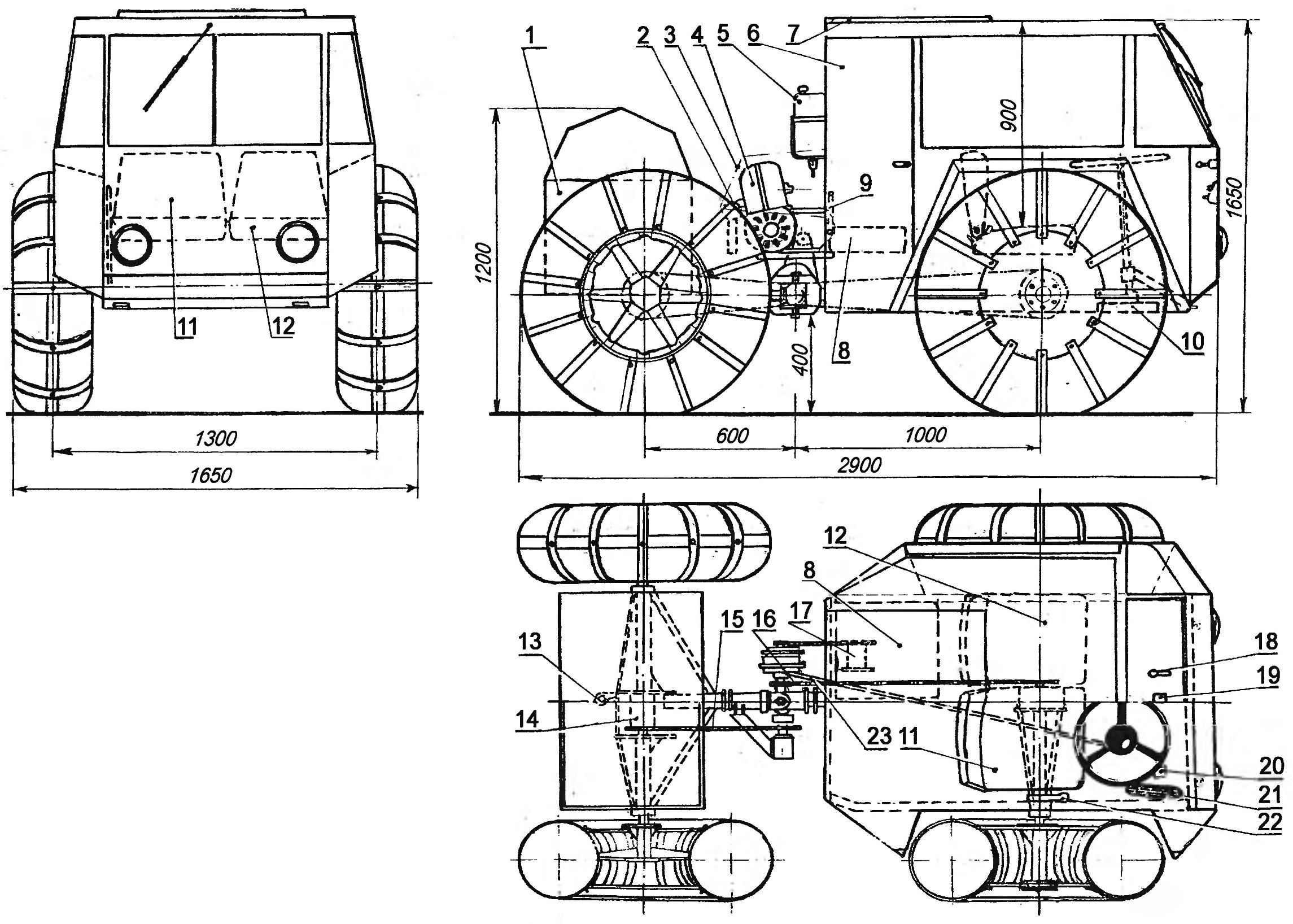
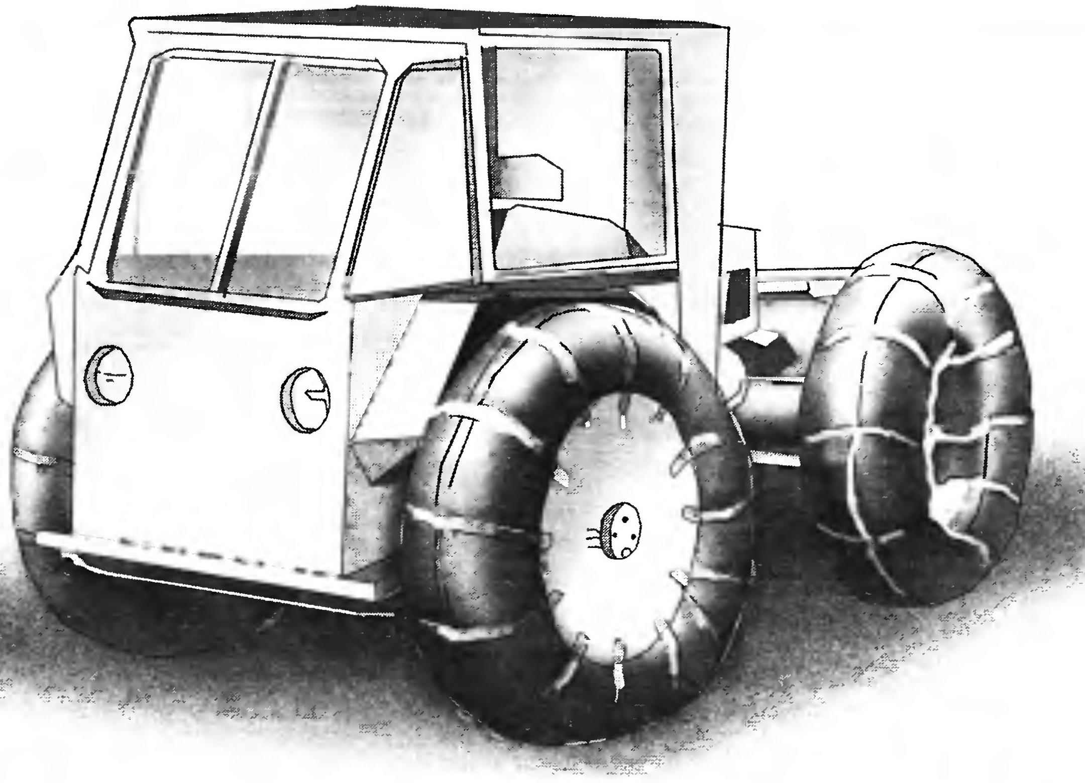 In the design of this Rover, the designer-a lover of L. Antonov of Kirishi of the Ryazan region have sought to make year-round and reliable off-road machine with small dimensions and weight, equipped with enclosed cab for three people — the driver and two passengers. The result was an all-terrain vehicle on the tires low pressure with the wheel formula 4×4, constructed according to the scheme of the vehicle with “broken” frame and with the original transmission.