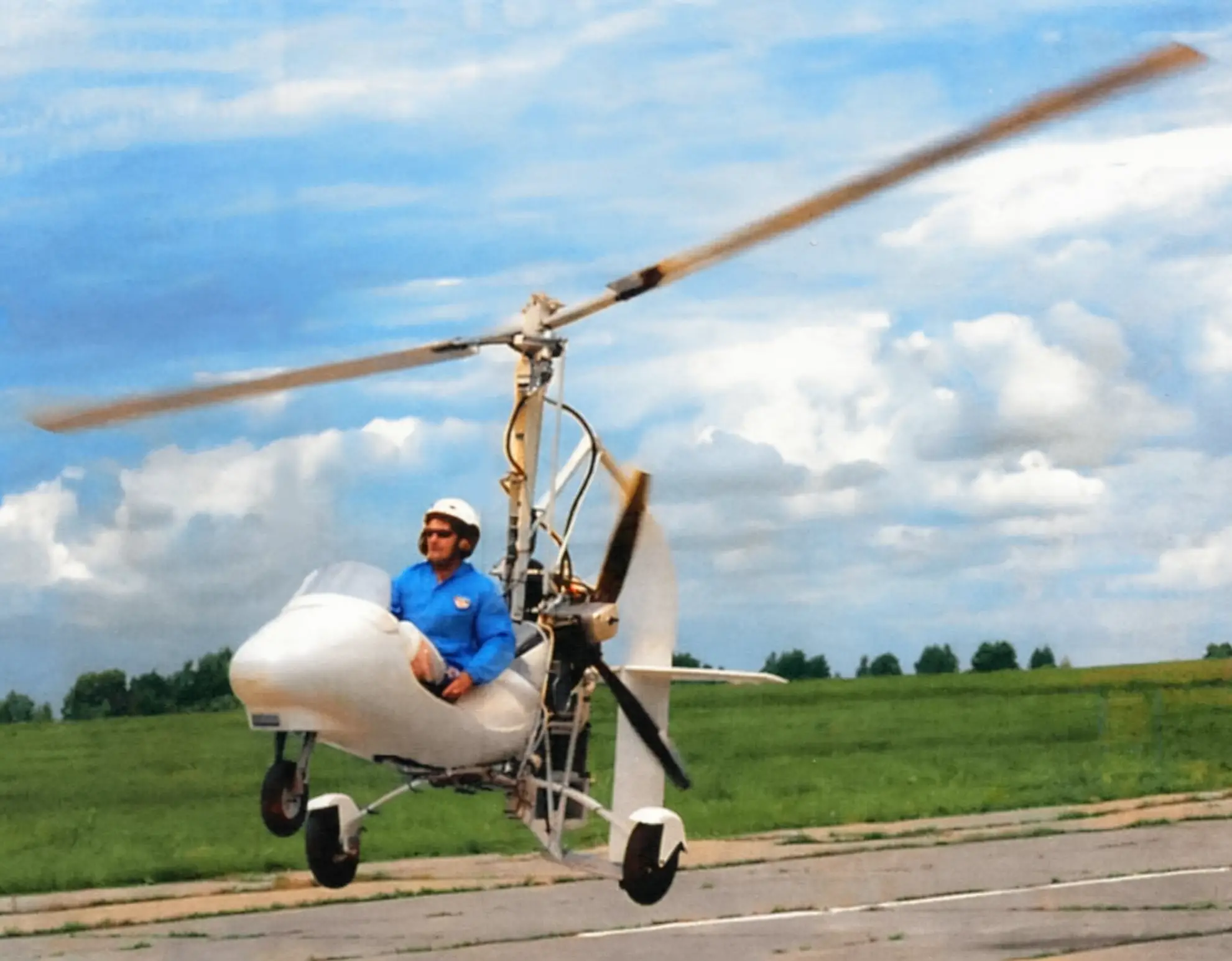
It is no exaggeration to say that the most important part of a glider-autogyro is the rotor. The autogyro’s flight qualities depend on the correctness of its airfoil, on mass, centering accuracy, and strength. True, the unpowered craft on a car tow rises only to 20–30 m. But even flight at such a height requires strict observance of all the conditions stated earlier.
The blade (Fig. 1) consists of the main load-bearing element — the spar; ribs (Fig. 2), with the gaps between them filled with foam plates; and a trailing edge made from a straight-grained pine strip. All these blade parts are glued with synthetic resin and, after proper profiling, are covered with glass cloth to add strength and airtightness.
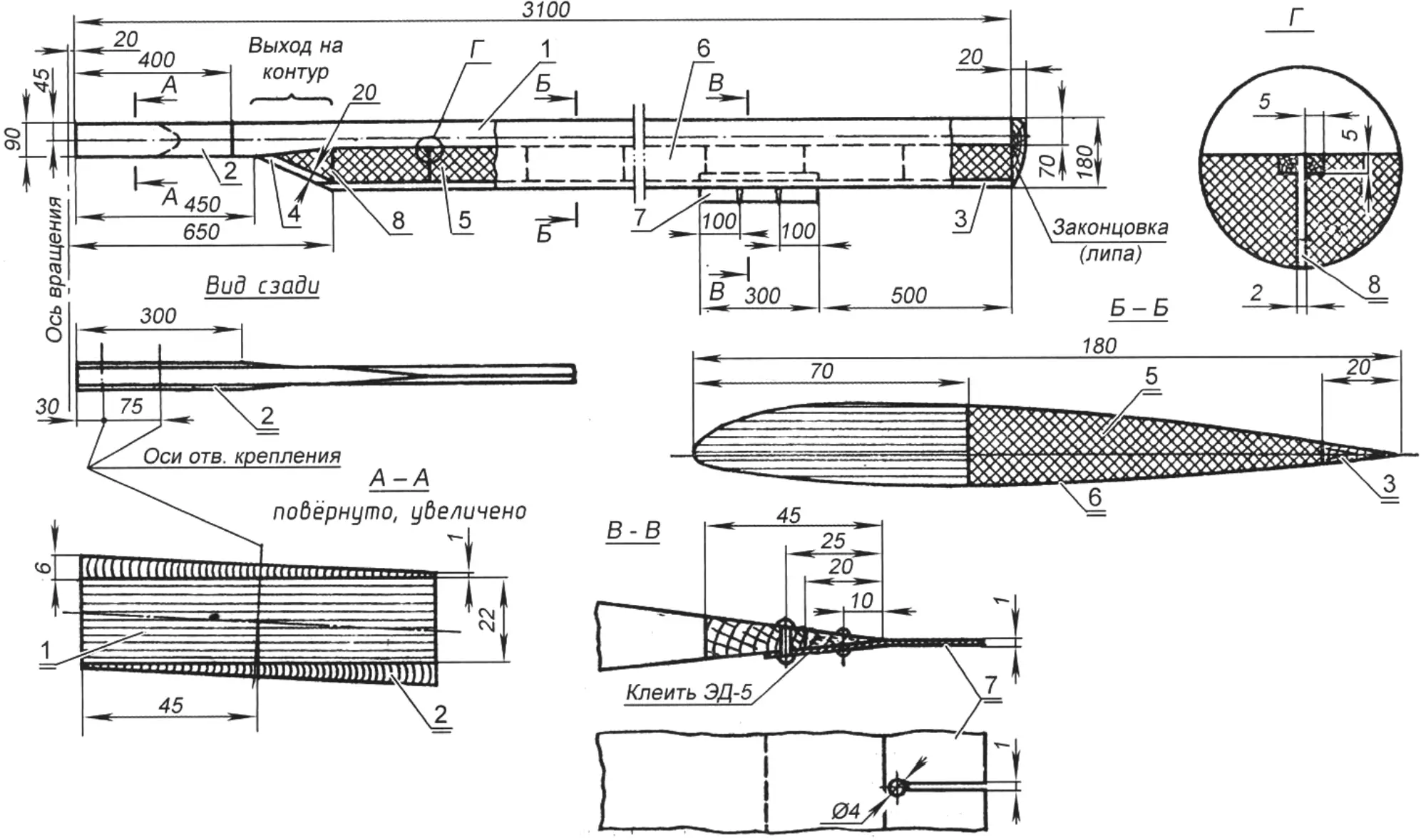
1 — spar (plywood bonded with glass cloth); 2 — doubler (oak or ash); 3 — trailing edge (pine or lime); 4 — strip (pine or lime); 5 — filler (foam); 6 — skin (2 layers of glass cloth s0.1); 7 — trim tab (D16M duralumin, s, 2 pcs.); 8 — rib (plywood s2, grain along)
Materials for the blade: aircraft plywood 1 mm thick, glass cloth 0.3 and 0.1 mm thick, ED-5 epoxy resin, and PS-1 foam. The resin is plasticized with dibutyl phthalate at 10–15%. The hardener is polyethylene polyamine (10%).
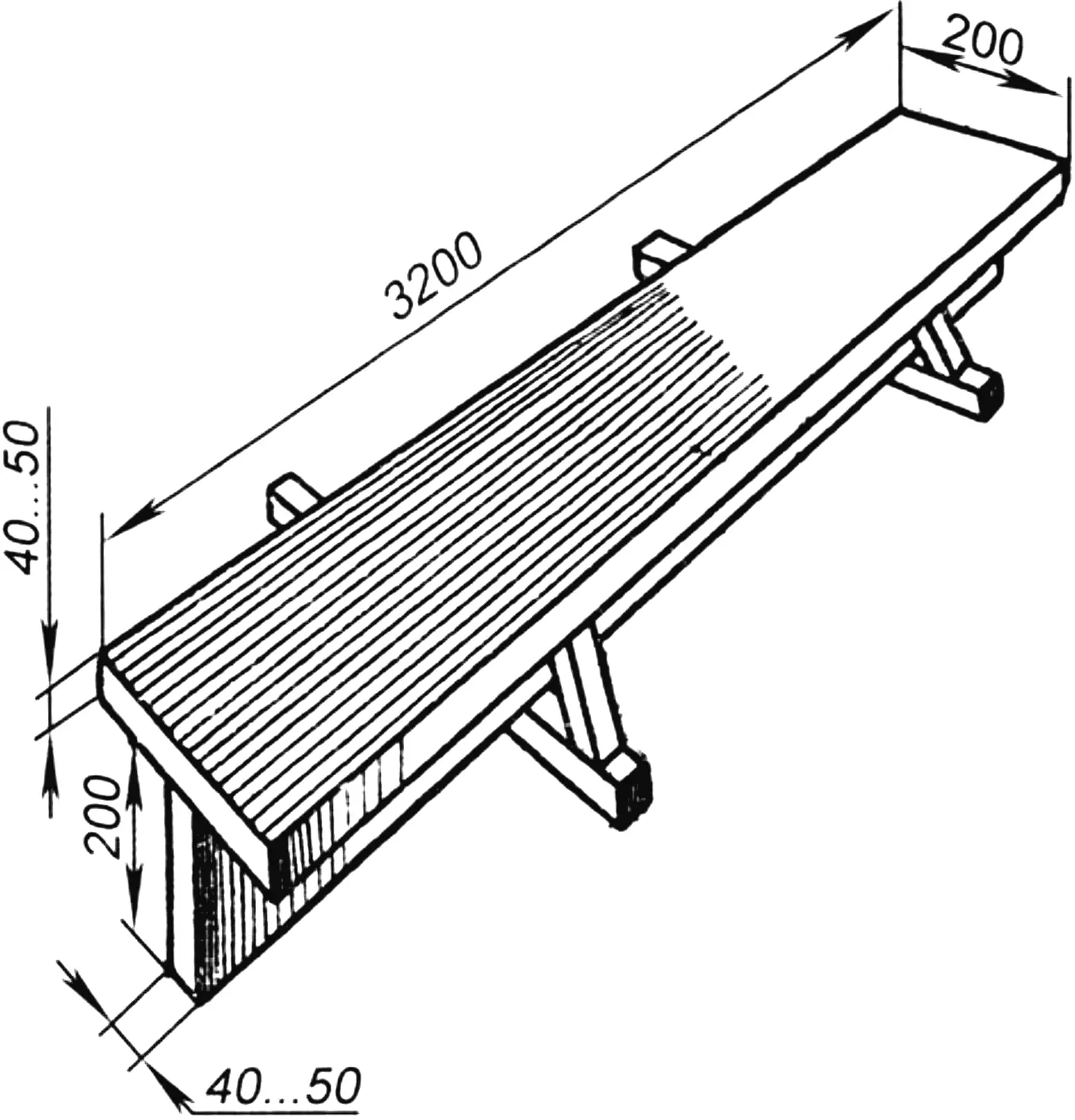
Spar manufacture, blade assembly, and subsequent machining are done on a jig that must be sufficiently rigid and have a straight horizontal surface as well as one vertical edge (straightness is ensured by planing against a fairing-type straightedge at least 1 m long).
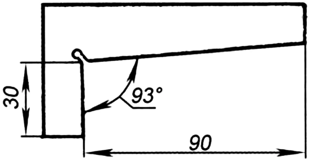
The jig (Fig. 3) is made from dry boards. To the vertical longitudinal edge (whose straightness has been ensured), metal setting plates are temporarily screwed during spar assembly and bonding, spaced 400–500 mm apart. Their top edges must rise 22–22.5 mm above the horizontal surface.
For each blade, prepare 17 plywood strips cut to the spar drawing with the outer ply along the length, with machining allowances of 2–4 mm per side. Since the plywood sheet size is 1500 mm, scarf joints of at least 1:10 are inevitable in each ply, and joints in one ply must be offset 100 mm from joints in the next. The plywood pieces are arranged so that the first joints of the lower and upper plies are 1500 mm from the root end of the spar; those of the second and next-to-last plies are 1400 mm, and so on; the mid-ply joint is 700 mm from the root end of the blade. Second and third joints of the prepared strips are distributed along the spar accordingly.
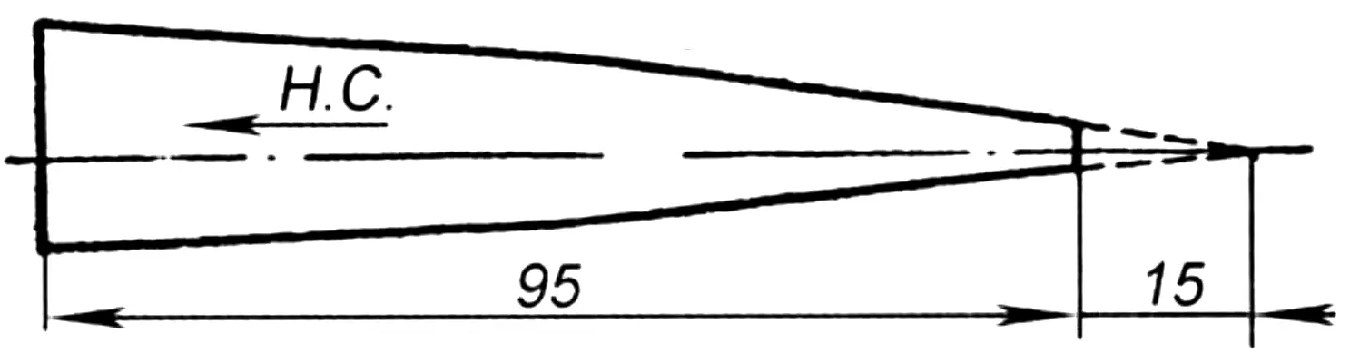
In addition, you need 16 strips of 0.3 mm glass cloth, each 95×3120 mm. They must first be treated to remove the size.
Bond the blades in a dry room at 18–20°C.
SPAR MANUFACTURE
Before assembling the blanks, cover the jig with tracing paper so they will not stick to it. Then lay and align the first plywood ply relative to the setting plates. Fasten it to the jig with thin short nails (4–5 mm), driven at the root and tip and one on each side of the joints to keep the plywood pieces from shifting on the resin and glass cloth during assembly. Since the nails remain in the plies, drive them staggered. Drive nails in the same order to secure every subsequent ply. They should be of sufficiently soft metal so as not to damage the cutting edges of tools used later on the spar.
Wet the plywood plies generously with ED-5 resin using a roller or brush. Then lay a glass-cloth strip on the plywood and smooth it by hand and with a wooden squeegee until resin appears on the surface. Next place a plywood ply on the cloth, first coating with resin the face that will lie on the glass cloth. Cover the built-up spar with tracing paper and place on it a batten 3100×90×40 mm. Clamp the pack between the batten and the jig with clamps spaced 250 mm apart along the full length of the batten until the pack thickness matches the top edges of the setting plates. Remove excess resin before it hardens.
Remove the spar blank from the jig after 2–3 days and machine it to 70 mm width in the airfoil section, 90 mm at the root, and 3100 mm between ends. At this stage the essential requirement is straightness of the spar face that will become the blade leading edge during later profiling. The face to which the ribs and foam filler will be glued must also be sufficiently straight. Machine it with a plane fitted with a hard-alloy knife, or as a last resort with bastard files. All four longitudinal faces of the spar blank must be mutually perpendicular.
PRELIMINARY PROFILING
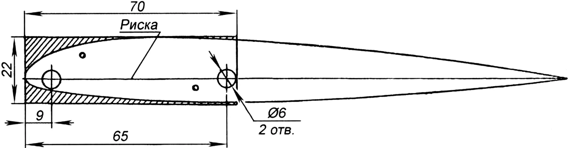
Mark the spar blank as follows. Place it on the jig and, on the tip end and on the front and rear faces, draw lines 8 mm above the jig surface (~Yl max). On the tip end also draw the full blade airfoil at 1:1 with the template (Fig. 4). High accuracy is not required for this auxiliary template. On the outer side of the template draw the chord line and drill two 6 mm holes on it — at the airfoil nose and at a point 65 mm from it. Looking through the holes, align the template chord line with the line drawn on the spar tip end to mark the profiling limit. To prevent shifting, fasten the template to the end with thin nails through arbitrarily placed holes of matching diameter.
Profile the spars with a simple plane (rough) and a flat bastard file. Check longitudinally with a straightedge. After machining, glue the ribs to the rear face of the spar. Installation accuracy is ensured by a chord line marked on the ribs during manufacture, aligned with the chord line on the rear face of the spar blank, plus a visual check of their straightness relative to the auxiliary template, which is again fastened to the tip end for this purpose. Space the ribs 250 mm apart; set the first at the start of the spar airfoil or 650 mm from the root end.
BLADE ASSEMBLY AND MACHINING
After the resin has cured, glue foam plates matching the aft blade airfoil between the ribs; cut slots in the trailing-edge strip at the projecting rib ends. Glue that strip to the ribs and foam plates with resin.
Next, rough-machine the foam plates, fitting their curvature to the ribs, and remove excess wood from the strip to form the trailing edge with some allowance for later precise finishing to the main template (Fig. 5).
Make the main template first with a 0.2–0.25 mm allowance on the template values Yu and Yl to obtain a slightly undersize airfoil for glass-cloth covering.
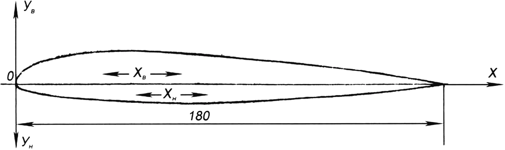
When machining the blade with the main template, take the lower surface as the datum. Check with a fairing straightedge the straightness of its generator at Xl=71.8 mm, where Yl=8.1 mm. Straightness is adequate if a 1 m straightedge shows a midspan gap of no more than 0.2 mm.
| Xu, mm | 1.0 | 2.7 | 5.1 | 9.8 | 13.6 | 17.5 | 27.0 | 36.2 | 54.2 | 72.2 | 90.2 | 108.2 | 126.1 | 144.1 | 162.0 | 171.0 | 180.0 |
| Yu, mm | 3.5 | 5.1 | 7.5 | 9.2 | 10.5 | 11.5 | 12.9 | 13.5 | 13.6 | 12.8 | 11.5 | 9.8 | 7.8 | 5.5 | 3.0 | 1.6 | 0.2 |
| Xl, mm | 2.6 | 4.5 | 8.3 | 11.8 | 15.2 | 18.5 | 27.0 | 35.8 | 53.8 | 71.8 | 89.8 | 107.8 | 125.8 | 143.9 | 161.9 | 171.0 | 180.0 |
| Yl, mm | 2.4 | 3.2 | 3.9 | 4.5 | 4.9 | 5.3 | 6.3 | 7.2 | 8.0 | 8.1 | 7.6 | 6.6 | 5.4 | 3.9 | 2.2 | 1.2 | 0.2 |
Then fasten guide rails of hardwood or duralumin, 8.1 mm high, to the long sides of a well-trued duralumin plate 500×226×6 mm. For the upper half of the main template the distance between them must equal the blade width, or 180 mm. Place the blade on the jig on 3–4 pads equal in thickness to the fixture plate and clamp it. The trued plate can then travel between the jig and the lower blade surface along the full length in a straight plane, keeping blade thickness constant and the surface true to the desired airfoil.
The upper surface may be considered finished when the upper template half travels the full length with no gap on the airfoil or where the template meets the guides. Check the lower surface with the fully assembled template, both halves rigidly joined. Profile the upper and lower surfaces with bastard files of coarse and medium cut; fill hollows and irregularities to the template with putty of ED-5 resin mixed with wood flour, then file again to the template.
BLADE COVERING
The next operation is covering the airfoil and root sections of the blades with 0.1 mm glass cloth in two layers on ED-5 resin. Each layer is a continuous glass-cloth tape centered on the leading edge. The main requirement is that after the cloth is well impregnated, excess resin must be thoroughly squeezed out with a wooden squeegee transversely from leading to trailing edge so that no air bubbles remain under the cloth. The cloth must not fold or wrinkle anywhere, to avoid unwanted thickenings.
After covering, sand the blades and bring the trailing edge close to final thickness. Also check the spar-nose airfoil. For now do this with the main template and the allowances noted above, to confirm the quality of the upper and lower surfaces.
Bring the main template to the required size and use it for final airfoil fairing with putty, again taking the lower blade surface as the datum; recheck with a fairing straightedge the straightness of its generator at Xl=71.8 mm from the nose. When satisfied, place the blade lower-face down on the jig on 42 mm pads (the rounded difference between the height of the lower template half and Yl=8.1 mm). One pad goes under the root, which is clamped to the jig there; the others are spaced arbitrarily along the blade. Then wash the upper surface with acetone or solvent and coat its full length with a thin layer of putty from ED-5 resin and tooth powder, thick enough to spread easily without running on the airfoil curve (consistency of thick sour cream). Advance the firmly assembled main template slowly and evenly along the blade, bevel leading, so that its edge always rests on the horizontal jig surface. By removing excess putty on convex areas and leaving what is needed in hollows, the template fairs the airfoil. If some hollows remain unfilled, repeat after applying a thicker putty coat. Periodically remove excess putty when it begins to hang from the leading and trailing edges. Keep the template square, without skew, and perpendicular to the blade axis, moving continuously to avoid surface irregularities. After the putty is fully hard and lightly sanded, repeat final puttying on the lower surface using 37 mm pads.
BLADE FINISHING
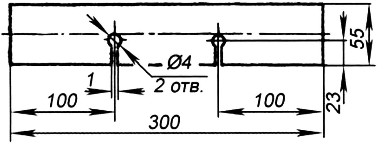
After making the blades, sand them with medium-grit paper, paying special attention to forming the airfoil nose; wash with acetone or solvent and apply Primer No. 138 everywhere except the trim-tab attach area (Fig. 6). Then fill all irregularities with nitro putty, avoiding excess thickenings on the profiled surfaces.
Final finishing — carefully removing excess putty with waterproof sandpaper of various grits — is done while advancing the closed template along the blade surfaces without excess rocking or gaps (no more than 0.1 mm).
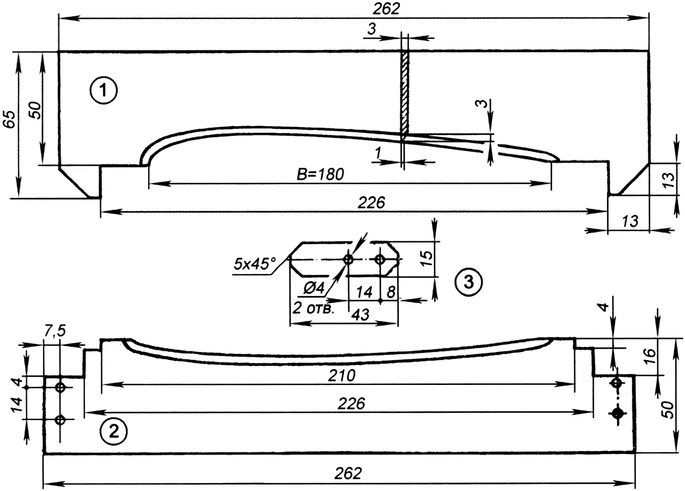
After covering the blades with 0.1 mm glass cloth and before priming, glue oak or ash plates 400×90×6 mm to the root top and bottom with ED-5 resin; plane them so the blades acquire an incidence angle of 3° between the chord and the horizontal plane. Check it with a simple template (Fig. 7) relative to the forward root face, and also check parallelism of the resulting top and bottom root surfaces.
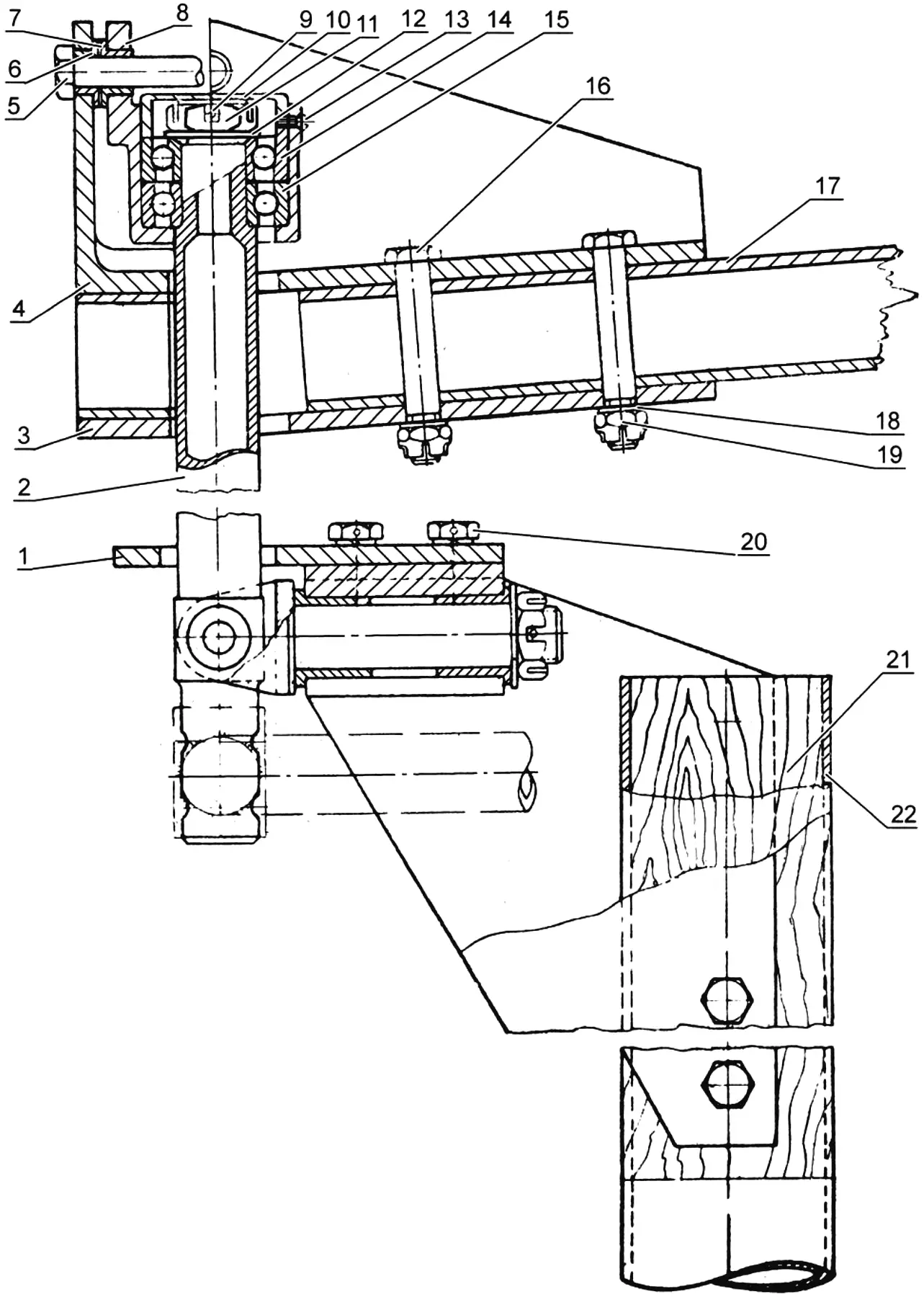
1 — angle limiter (D16T); 2 — rotor shaft (30KhGSA); 3 — lower hub plate (D16T, s6); 4 — hub yoke (D16T); 5 — main hinge pin (30KhGSA); 6 — bushing (tin bronze); 7 — washer Ø20–10, 5–0.2 (steel 45); 8 — bearing housing (D16T); 9 — cotter-pin hole; 10 — bearing-housing cover (D16T); 11 — castle nut M18; 12 — washer Ø26–18, 5–2 (steel 20); 13 — cover screw M4; 14 — angular-contact bearing; 15 — self-aligning radial bearing No. 61204; 16 — blade attach bolt (30KhGSA); 17 — blade doubler (s3, 30KhGSA); 18 — washer Ø14-10-1.5 (steel 20); 19 — self-locking nut M10; 20 — screw M8; 21 — sleeve (Ø61, L = 200, D16T); 22 — pylon (tube Ø65×2, L=1375, lime)
This completes root forming; cover the root with 0.3 mm glass cloth on ED-5 resin for airtightness. The finished blade, except the root, is painted with nitro enamel and polished.
Advice on finding the actual center-of-gravity position of the blades, balancing them, and mating them to the hub will appear in later issues of the magazine.
ASSEMBLY AND ADJUSTMENT
The previous issue described in detail the technology of making autogyro rotor blades.
The next stage is chordwise blade balancing, then assembly and radial balancing of the rotor. Smooth rotor operation depends on accurate blade installation; otherwise excessive unwanted vibration will appear. Therefore take assembly very seriously — do not rush, and do not start until all tools and fixtures are on hand and the workplace is prepared. During balancing and assembly constantly check your actions — better measure seven times than fall even from a small height once.
Chordwise balancing here means finding the center of gravity of a blade element.
The main reason for chordwise balancing is to reduce the tendency toward flutter-type oscillations. Although such oscillations are unlikely on the machine described, keep them in mind and, when adjusting, do everything possible so that the blade CG lies within 20–24% of chord from the airfoil nose. The NACA-23012 blade airfoil has very little movement of the center of pressure (CP — the point of application of all aerodynamic forces on the blade in flight), which lies in the same range as the CG. That lets the CG and CP lines coincide, meaning practically no force couple twisting the rotor blade.
The proposed blade design gives the required CG and CP positions if built strictly to drawing. But even with careful material selection and process control, weight mismatch can occur, which is why balancing is done.
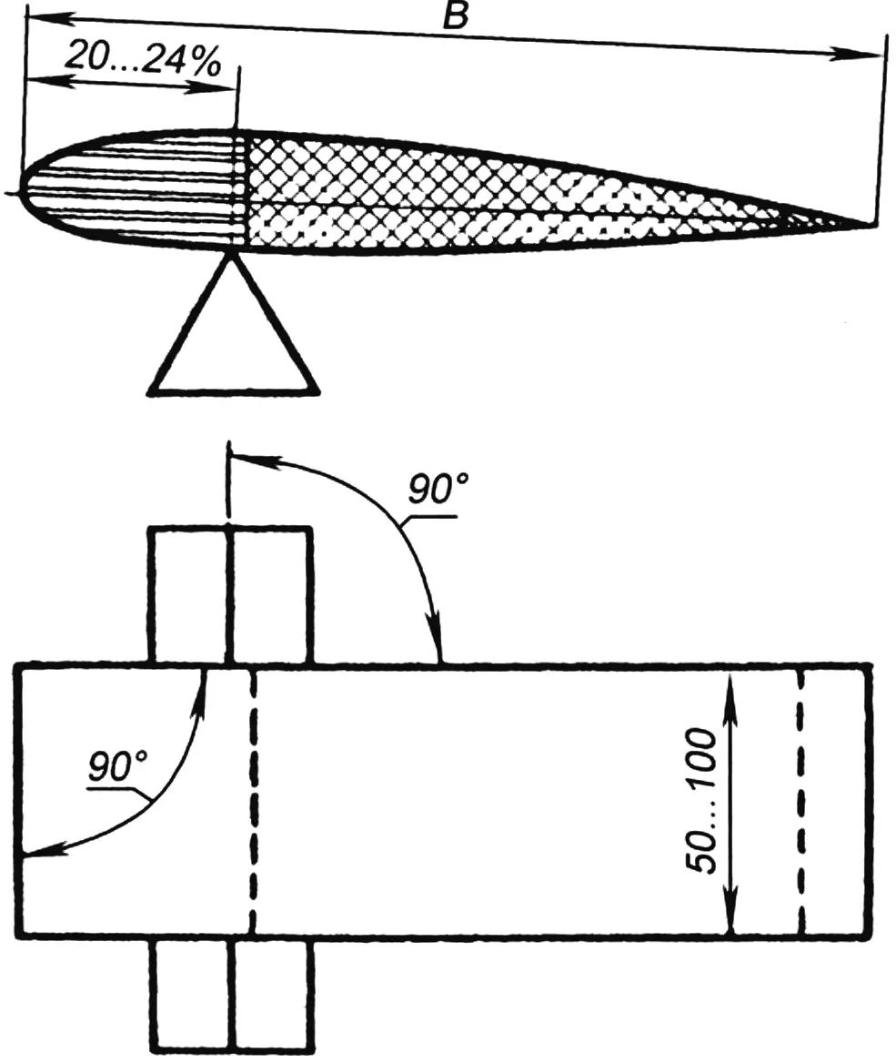
You can determine (within acceptable error) the CG of a finished blade by making blades with 50–100 mm tip allowances. After final filing, cut off the allowance, fit a tip cap to the blade, and balance the cut-off element.
Place the blade element lower face down on a triangular horizontal prism (Fig. 1). Its chordwise section plane must be strictly perpendicular to the prism edge. By shifting the element along the chord, bring it to balance and measure the distance from the airfoil nose to the prism edge. That distance should be 20–24% of chord length. If the CG exceeds this maximum limit, hang an anti-flutter weight on the airfoil nose near the tip so the CG moves forward as required.
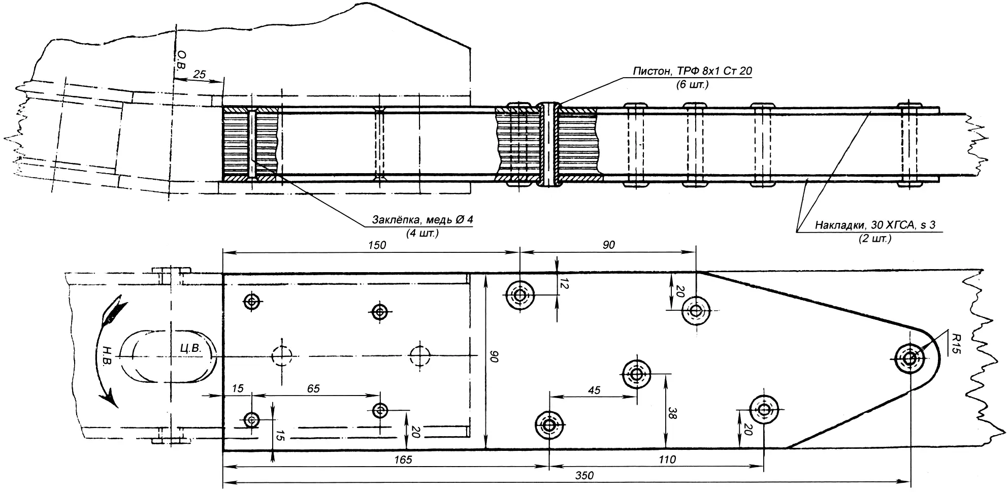
The blade root is reinforced with doublers — 3 mm steel plates (Fig. 2). They are fastened to the root with 8 mm tubular rivets and flush solid rivets using adhesive BF-2, PU-2, ED-5, or ED-6. Before installing the doublers, rough-sand the root and grit-blast the doubler. Degrease and thoroughly coat with adhesive the bonding surfaces — root, doublers, rivet holes, and rivets. Then expand the tubular rivets and set the solid rivets (4 per doubler). After that the blades are ready for layout for hub installation.
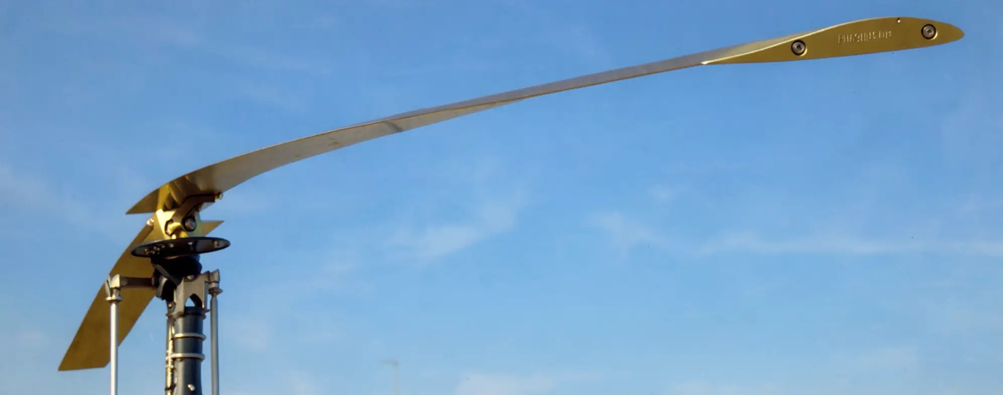
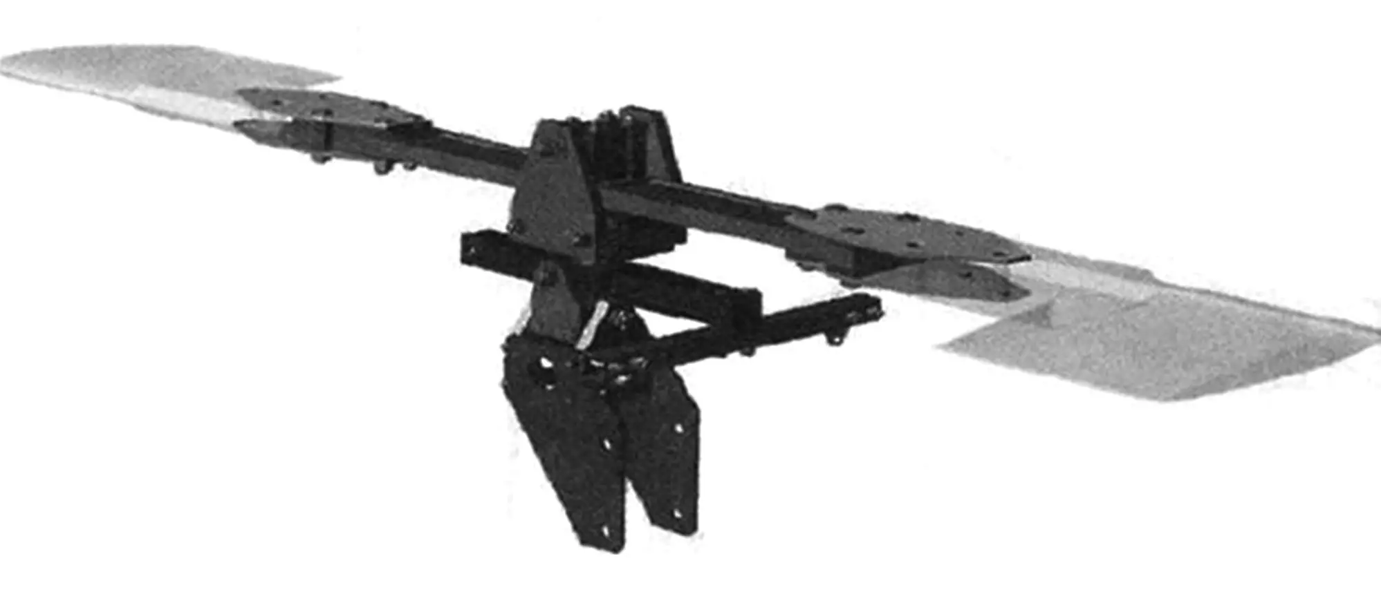
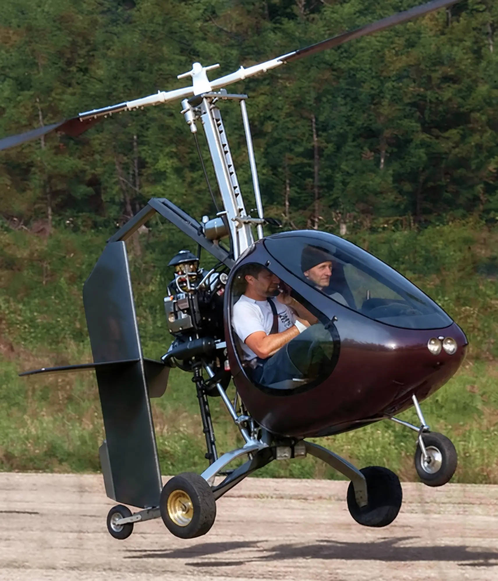
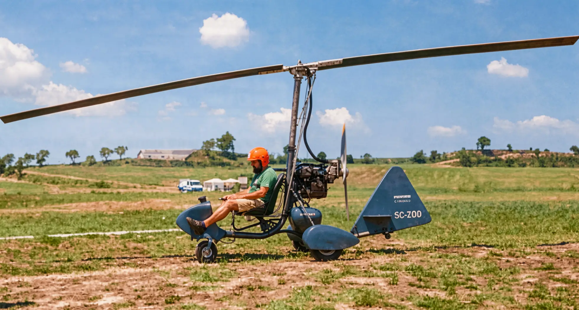
The autogyro rotor (Fig. 3) consists of two blades, a hub, a rotor shaft with rolling bearings, a teeter-hinge bearing housing, and a rotor-axis tilt limiter.
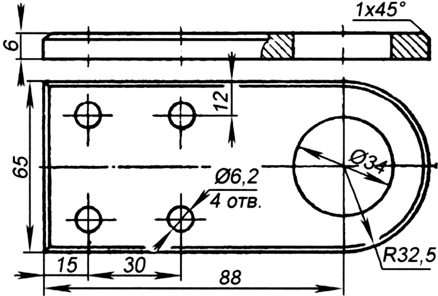
The hub has two parts: a U-shaped yoke and a lower plate (Fig. 4). Preferably make the yoke from a forging. If made from bar stock, the grain direction must be parallel to the yoke longitudinal axis. The same grain direction is required for the lower plate, cut from 6 mm D16T duralumin sheet.
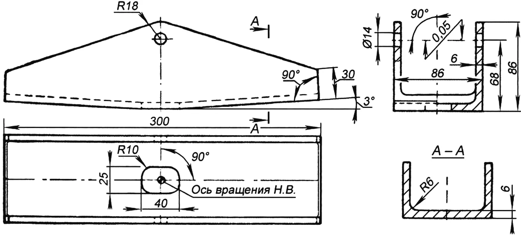
Machine the yoke in this order: first mill the blank leaving 1.5 mm per side, then heat-treat (harden and age), then finish-mill to the drawing (see Fig. 4). Next remove all transverse tool marks with a scraper and sandpaper and apply a longitudinal polish stroke.
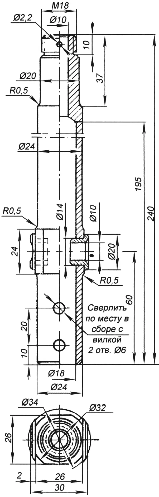
The shaft (Fig. 5) is mounted on the pylon on two mutually perpendicular axes that let it tilt from the vertical by the prescribed angles.
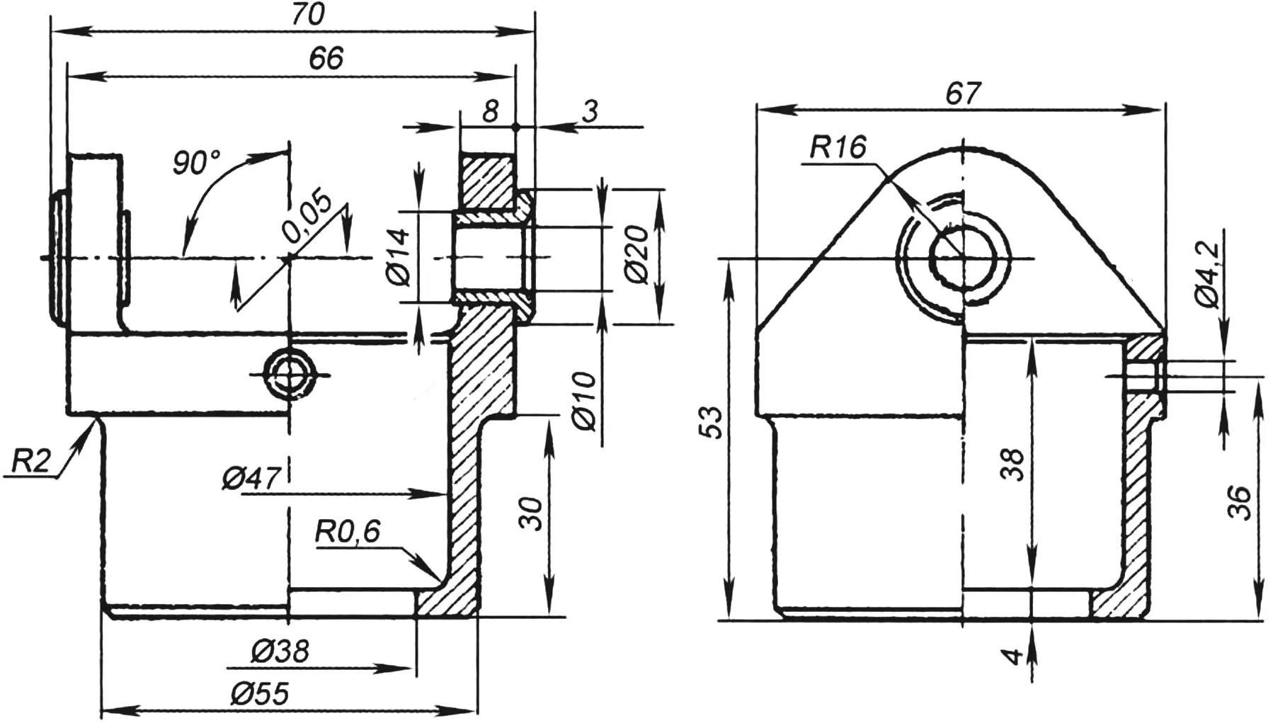
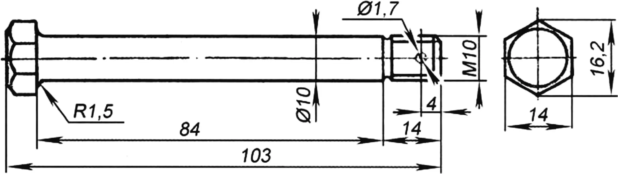
Two rolling bearings are fitted on the upper shaft: lower — radial No. 61204; upper — angular-contact No. 36204. The bearings sit in a housing (Fig. 6) whose lower inner flange takes the full autogyro weight load in flight. When making the housing, pay special attention to the junction of the flange and the cylindrical part; undercuts and tool marks there are unacceptable. At the top the housing has two ears with pressed-in bronze bushings. Ream the bushing bores after pressing. The bushing axis must pass through the housing rotation axis strictly perpendicular to it. Through the housing ears and the bushings pressed into the yoke cheeks passes a bolt (Fig. 7) that forms the autogyro rotor teeter hinge, about which the blades flap.
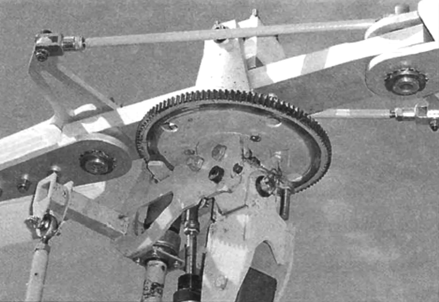
Shaft tilt, and thus disk plane attitude, is limited by a plate fixed on the pylon (Fig. 8). That plate keeps the rotor within angles that preserve autogyro pitch and roll control.
“Modelist-Konstruktor” No. 2’2014, B. BARKOVSKY, Yu. RYSYUK
Recommend to read
 HILLER-ARMREST
Do not consider it shameful to use a good development designers and lovers they share the magazine. But, armed with their interesting ideas and technical solutions, and the very creative... WITH A KNIFE AS A LEVER
The longest of the kitchen knives the mistress used primarily for cutting large vegetables, meat fish, that is, for the most time-consuming operations for the preparation of food. To...
