
 The idea was truly grandiozny is to design and build a versatile vehicle, able to move confidently off-road (land version) and be speedy and reliable afloat (boats). After a few years the boat amphibian was ready and passed first tests. Started normal stage of refinement, enhancements, improvements, ride quality and handling. In between working in the garage was the shows long passages, test runs in road conditions and water crossings.
Even today we cannot say that the work on the boat completed. Changes in the steering, improving the design of suspensions. The version which is published in this number, is one of the most complete. The wheels and the propeller of this machine is “wrapped around” has more than one thousand kilometres of roads and miles of waters.
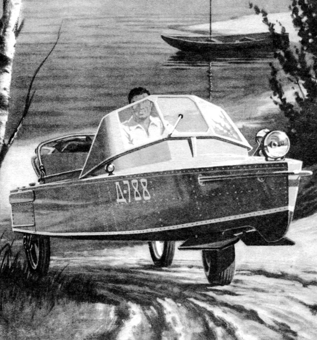
Boat-amphibian “Swallow” performed at the tricycle scheme, thereby simplifying it to improve the flow and hence increase the speed of movement in the water. And rear (drive) wheels, and the propeller shaft rotated by the engine of the scooter “Tula 200” with forced air cooling. When traveling short distances thruster on permanently when far off – this operation takes a few seconds.
Duralumin hull-amphibian consists of transverse and longitudinal framing. It is divided into five airtight compartments with a total capacity of 240 liters, which prevents the machine from flooding. To protect the driver and passengers used lightweight folding awning and a wind deflector mounted in front of the cabin (Kok-Pete).
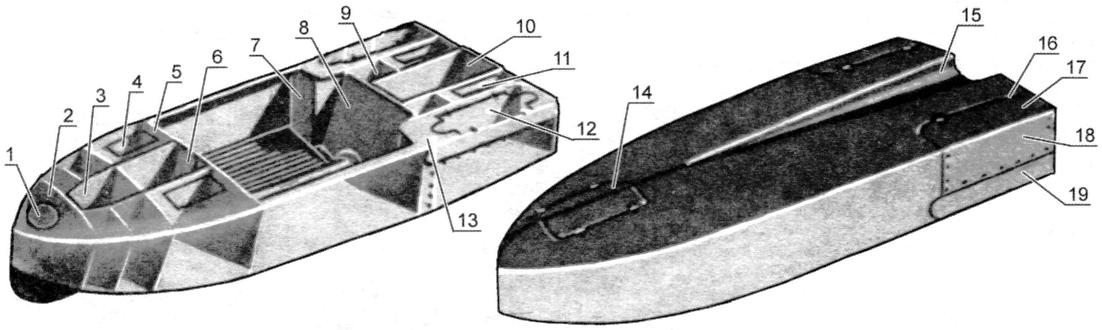
The hull-amphibian:
1 – Luke nose compartment; 2 – front compartment; 3 – the hatch to the nose wheel; 4 – hatch 4th sections; 5 – deck; 6 – the hatch of a steering; 7 – strengthen the body; 8 – rear wall sections; 9 – an access hatch to the engine compartment; 10-engine compartment; 11-strengthening of the casing; 12-the hatches of the rear wheels; 13 – cover; 14 – fold hatch nose-wheel; 15 – groove; 16 – loop hatches rear wheels; 17, 18 – fold for mounting the rear wheels; 19 – removable part of the hull plating
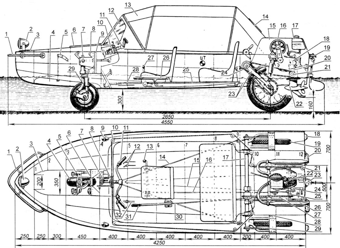
Boat-amphibian “Swallow”. Layout (side view):
1 – safety-arc; 2 – headlamp; 3 – deck the bow; 4 – fold hatch front wheel; 5 – the lever of the hatch closing the sash; 6 – cover the nose hatch; 7 – suspension components front fork with wheel 400х150; 8 – the plug retainer in the retracted and released positions; 9 – frame of the suspension unit of the front fork; 10 – steering gear; 11 – the steering wheel; 12 – windshield; 13 – folding awning; 14 – rear window; 15 – cover of the engine compartment; 16 – fan 17 – fuel tank; 18 – motor; 19 – steering device; 20 – mount sub-frame; 21 – shaft propeller; 22 – deadwood propeller; 23 – pendulum suspension fork rear wheel; 24 – rope braking device; 25 – soles; 26 – the lever starting the engine; 27 – shift lever; 28 – brake light switch; 29 – fork front suspension
Layout (top view):
1 – safety-arc; 2 – headlamp; 3 – the hatch to the nose wheel; 4 – nose wheel; 5 – tie-rod; 6 – power frame suspension front wheel; 7 – pinion steering gear; 8 – drum designated place; 9 – navigation light (right – green, left – red); 10 – a pulley of a designated place; 11 – control handle gas; 12 – fittings control cable clutch and gas; 13 – gear lever; 14 – brake; 15 – bottom tunnel; 16 – thrust of the gear selector; 17 – rear axle with suspension forks; 18 – tail lights; 19 – driving wheel; 20 – handle; 21 – roller designated place; 22 – gearbox drive propeller; 23 – pulley steering; 24 – kick-starter; 25 – clutch enable the transmission to the wheels; 26 – muffler; 27 – intermediate chain; 28 – mounting bracket of the suspension; 29 – leading circuit; 30 – rope start engine; 31 – starting lever; 32, a flexible cushion speedometer
All three wheels of the boat-amphibians have independent suspension with spring-hydraulic shock absorbers of telescopic type. In the described embodiment shows a motorcycle wheel, but in accordance with the requirements of a self-made cars desired vehicle steering wheel.
For the movement in the water the wheels retract and the hatches of the hull. This surgery takes about 10 minutes and made it so. Amphibious vehicle enters the water to the position of “afloat”, the transmission is put in neutral position, and the wheels manually with levers retracted in the hatches. Then removed the bolt on the steering shaft, turn on one of the gears on the propeller (matched to load) – now you can go sailing.
Exit the water in reverse order.
Amphibious-equipped rearview mirror, instrument panel, speedometer, audible signal, lamp, light turn signal.
Wishing to build a similar boat-amphibian can recommend to install a more powerful and modern engine and transmission on the water the engine to perform according to the scheme: the output shaft of the power unit – gearbox – propeller. It is necessary also to provide for adjustment of the depth of immersion of the screw, that will eliminate the cavitation at planing.
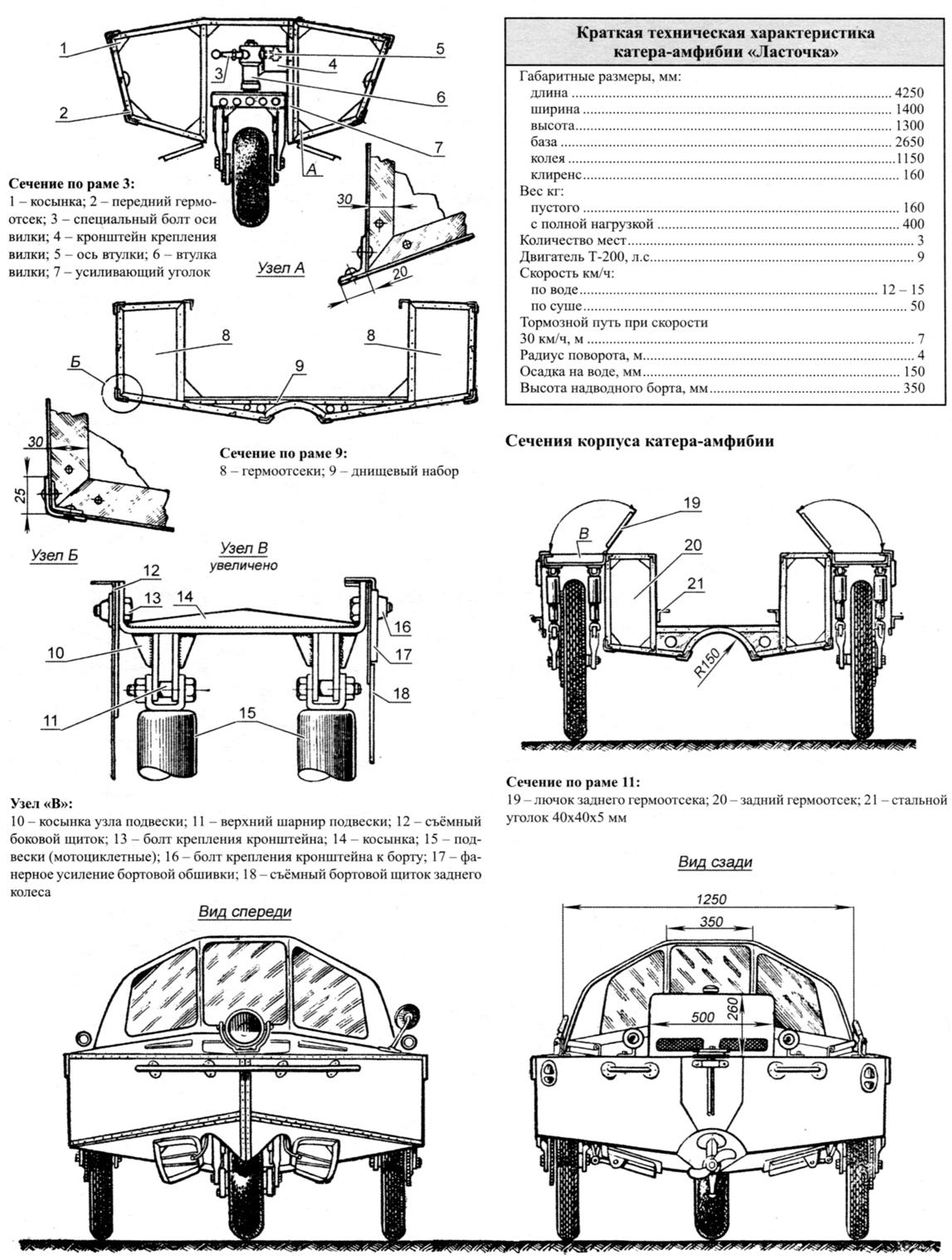
Corps amphibious dural, riveted bearing. Cross pack includes twelve frames (frames) collected from the corners of the cross section of 30x30x2 mm, bonded dural gussets thickness of 2 mm. Skin (1.2 mm thick) frames 1, 4, 10 and 12 serves as a bulkhead of a pressurized compartment. There is a cutout in the casing for the differential and chain. Longitudinal set consists of pairs of keel profiles, going from the 4th to the 12th frame and forming the edge of the trough, the Malar, the two on-Board profiles, four bottom, two side and two stringers of the bulwark the size of 20x20x2 mm. Zygomatic profiles are from the bow to the frame 9. On the hull along the keel, bilge and side angles riveted profiles (25x25x1,5 mm). Trim and profiles, between which there is a hermetic, have a greater stiffness and better tightness of joints. The cracks formed for the passage of stringers and profiles using pressurized compartment, sealed from the inner side with epoxy putty. At a distance of 100 mm ahead of the frame 4 vclean power frame consisting of two vertical, two horizontal angles (20x30x2 mm), sheathing (2 mm), four scarves (2 mm) and two high strength steel parts (30x30x2 mm), which are attached to the bracket and the fixing lugs of front fork. Riveted to the frame 4 of the Luggage box is divided into three sections. In the centre of the box outside the fortified instrument panel on which are mounted speedometer, lights, and switches.
Behind the frames 9 and 12 of the side plating reinforced by plywood strip with the longitudinal side profiles creates additional rigidity.
For the supply of water to the propeller screw from the frame 4 to 12 in Kiel made the groove gradually increasing in depth and width. Between the frames 11 and 12, the covering of the trough inner side is reinforced with additional aluminum plate (2.5 mm) and two longitudinal bearing parts (20x20x3 mm) for attaching gearbox and deadwood propeller. On the inner side in the area of the engine compartment paneling transom is reinforced with a sheet of aluminum (2 mm) and two vertical parts (20x30x2 mm) to stiffen this part, as the vibration from the engine is transmitted to the motor bracket frame, mounted on the transom. All frames and trim painted first nitrogenatom, and then aluminum with enamel inside, blue nitro enamel – sides and deck, and the red nitro enamel – the bottom and sash on the outside of the hatches.
Front wheel (ø 400 mm and width 150 mm) is rotated on an axis fixed in dural levers which are backed with steel plates on the motorcycle prinovozemelsky dampers. Arm, swivel seat with fork, sealed bearings No. 202. Fork welded from steel tubes (Ø30 mm with a wall thickness of 1.5 mm) and 2.5 mm plates welded in the middle of a light axis of the fork (Ø30 mm with wall thickness 5 mm). In the upper part of the axis there is a through hole with thread М14х1 for mounting starbolt tie rod. Bushing fork steel, with a wall thickness of the edges of 7 mm, and in the middle a 4 mm In the upper part is made a slot on polumetra sleeve for the passage of specbatal when turning the wheel. Opposite the welded axle bushings (Ø18 mm) with a shoulder for rotation of the plug when cleaning the wheels. Axis starbolt and sleeve coincide, so as in the retracted and released position, the bolt only rotates the rod tip, maintaining a constant position relative to the sleeve. To the bottom of the sleeve is welded on the lug of the striker, which is included in the steel lugs on the power frame. It is fixed on long journeys with a bolt and a nut and cotter pin, and at near – lock. Internal diameter of the lower part of the sleeve is made a groove in the form of a bronze ring serving as a bearing. At the top of the pipe sleeve is welded with the eyelet for fixing the plug in the retracted position. Mounting bracket plug welded from a sheet of 2.5 mm steel, is attached to the power corner (20x20x3 mm) on the vertical wall of the hatch and corners on the power frame bolts M6.
Rear axle is a split design (for easy mounting), consisting of three parts: the left and right forks (with housing and half shafts) and differential chain sprocket.
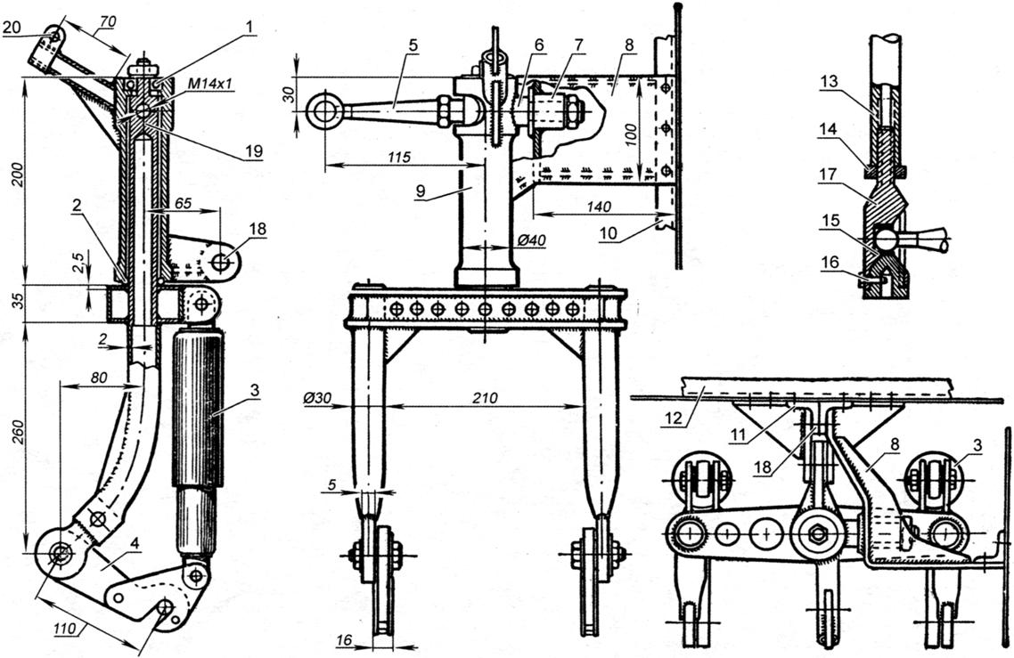
Front fork:
1 – ball bearing No. 201; 2 – bronze ring; 3 – prinovozemelsky shock absorber; 4 – lever; 5 – special bolt with ball bearing; 6 – axle fork sleeve; 7 – bushing holder; 8 – bracket; 9 – bushing fork; 10 – power angle; 11 – power squares; 12 – power frame; 13 – tie-rod; 14 – nut; 15 – bronze liners; 16 – bolt; 17 – a tip of pull-rod; 18 – locking pin or bolt M12; 19 – axle fork; 20 – the latch or bolt M8
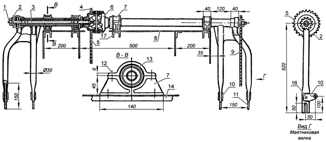
Rear axle with forks:
1 – roller; 2 – an asterisk of chain; 3 – a pipe Ø20×24; 4 – chain transmission to the intermediate roller; 5 – chain sprocket of differential gear; 6 – differential; 7 – Shoe mount of rear axle; 8 – frame № 10; 9 – chain drive wheel; 10 – plate for mounting the suspension; 11 – plates for the attachment of the wheel axles; 12 – bolts M6; 13 – bronze liners; 14 – corners-accelerator to the bracket on the frame No. 10; 15 – the bearing № 304; 16 – the hole; 17 – power profiles on the frame No. 10
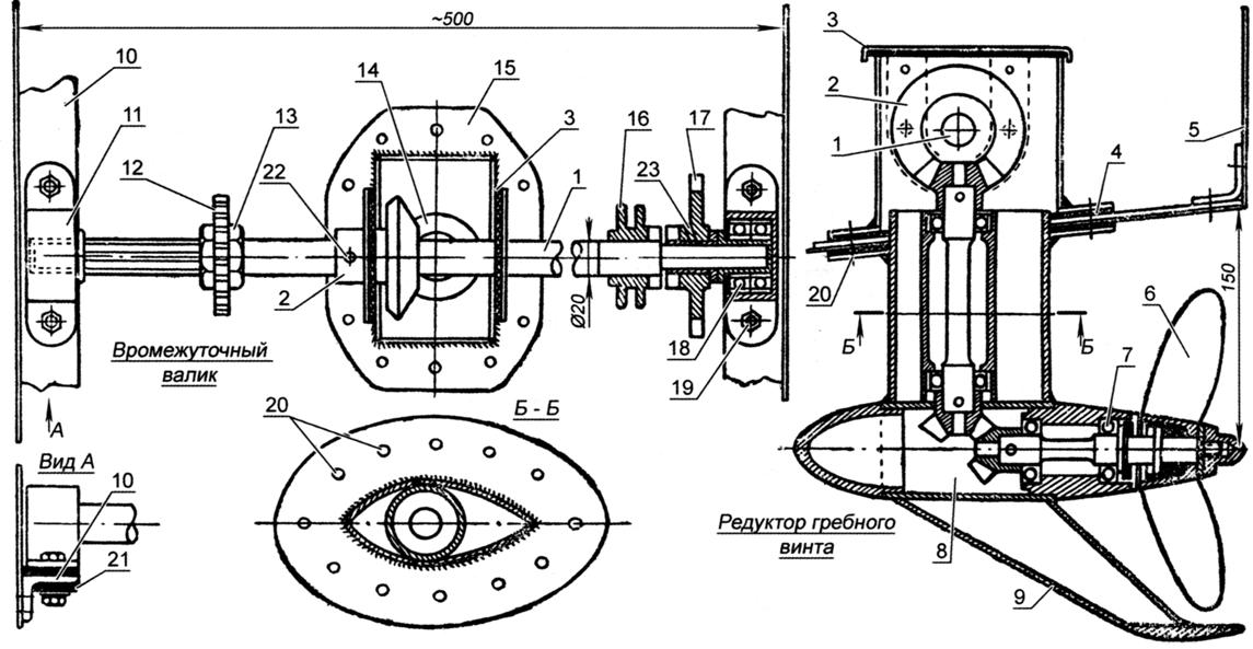
Intermediate the roller and the gear of the propeller:
1 – the intermediate roller; 2 – gear transfer roll; 3 – rubber gasket; 4 – strengthening plating gutters (aluminum, sheet s2,5); 5 – the covering of transom; 6 – propeller; 7 – angular contact bearing 203; 8 – housing; 9 – safety crutch; 10 – area-amplifier 40x40x5; 11 – bracket intermediate roller; 12 – sprocket (motorcycle); 13 – nut; 14 – gear; 15 – gearbox; 16 – coupling; 17 – the chain gear from the IZH-49; 18 – ball bearing No. 204; 19 – a bolt 8; 20 bolt M6; 21 – paranicheva strip; 22 – pin or bolt MB; 23 – hole for lubrication
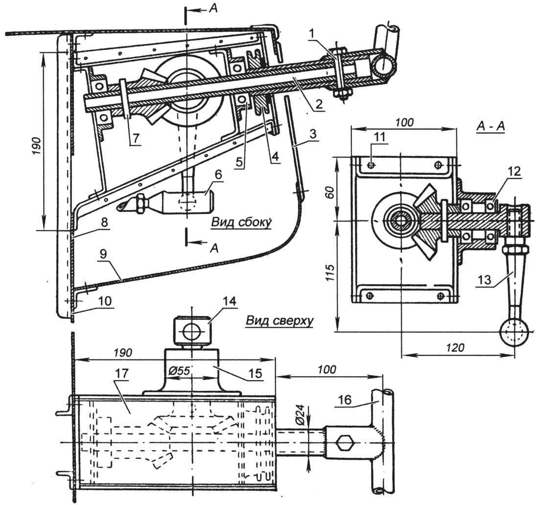
Steering gear:
1 – locking bolt; 2 – roller; 3 – instrument cluster; 4 – pulley; 5 – a bearing No. 204; 6 – dashboard; 7 – tie rod; 8 – frame No. 4; 9 – trunk lining; 10 – power angle; 11 – bolt M6; 12 – bearing No. 204; 13 – a special bolt; 14 spindle; 15 – bearing housing; 16 – steering wheel; 17 – the case of mechanism
The plug housing is a welded construction of pipes with wall thickness of 2.5 mm, with welded gussets for added strength in the transverse direction. Worn on the body and welded steel bushings for mounting the body in the Shoe and insertion of the bearings for the rollers of the axles. The drive axle consists of two rollers at the ends, connected by a steel pipe Ø24×20 mm with four M6 studs. Single roller ends with a square cross-section for coupling with the gear differential and the other with slots for mounting the chain gears. The differential is of conventional type. Spargalki axis satellites with square head, counter the special plates with square holes. Plate with seal is attached to the differential housing with three bolts with M6 thread. The differential from the passenger cabin is closed by a casing mounted on the frame with ten threaded bolts M5. Shoes axle bracket cast aluminum. The method of fastening them to the frame visible in the drawing. To the ends of the forks are welded steel plate with thickness 3 mm for mounting motorcycle suspensions. The top suspension lug is fixed to the steel bracket. When cleaning the wheels turn eight M8 bolts securing the brackets to the body, and together with pendants, forks and wheel brackets are raised to the neckline of the top plating hatches; plug locked into position, and the bottom hatch is closed by a flap. Wheel of the motorcycle M1-M with spokes with a diameter of 4 mm.
The engine compartment is located between frames 10, 12 and vertical walls of the pressurized compartment. It is a motor, an intermediate roller with a box of gears, chain transmission from the motor to the roller and from the roller to the differential, idler circuit of the differential rollers of the gear, start the engine and the battery. On top of the engine compartment is closed by a cover, in rear of which is mounted a tank capacity of 10 l. the Frame of motor is welded from steel tubes (Ø30×27) and is attached at three points to the brackets with rubber gaskets. The tension of going to the roller chain is adjusted by changing the number of washers mounted on the bolt attaching the frame to the rear bracket. The intermediate roller rotates in the brackets. Bearings are double: in the inner holes of the brackets are pressed steel transition sleeve for joining the roller bearing No. 204. Brackets with gaskets from paronite (to reduce noise) are attached with M8 bolts to the corners, mounted on the vertical walls of the engine room from 10-th to 12-th body frame.
Steering consists of dural steering box with two pressed and mounted on the vertical walls of the bearings, in which rotates a lightweight steel steering roller and a wall thickness of 5 mm. the Gear ratio of the gears is 1:1,5. On the projecting end of the roller is free to rotate the drum (with welded hub and wheel) for fixing the rope, going through a series of rollers to the rudder pulley. When the land steering roller with bolt or latch connected with bushing of the drum, and hence with the steering wheel. When moving through the water bolt is removed, and the force on the lever tie rod is not transmitted. Tie rod made of steel pipe with a diameter 12×8 with thread M10x1,5 for fastening steel tips.
V. BOVYKIN
Recommend to read
 ROAD NOT WORSE THAN SPORTS
The disadvantages road bike in the first place I take them is small compared with the sports speed. But it would be nice to have a universal machine that could confidently move around...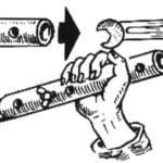 LONGER MEANS STRONGER
To give greater force wrench, it is often put on the pipe, thereby lengthening the lever. However, you have to work with an eye to the fact that the key may fall out of the pipe. But is...
