BRO-11M – STEP INTO THE SKY

BRO-11M - STEP INTO THE SKYDid you know that a lot of aircraft Amateur-built are based on BRO-11M – glider initial training famous Lithuanian aircraft designer B. I. Oscines. Very easy to manufacture and reliable in operation, designed on the basis of classical schools of design of aircraft of the 1930-ies, the glider won the sympathy not only of beginners glider, but Amateur aviators, who saw in the design of the BRO-11 M, and its elements useful for the creation of Amateur gliders and airplanes. While some used the scheme of the airframe as a whole, others copied the design of the wing, a third of its original control system… Word, BRO-11M was a kind of tutorial of novice aviators.

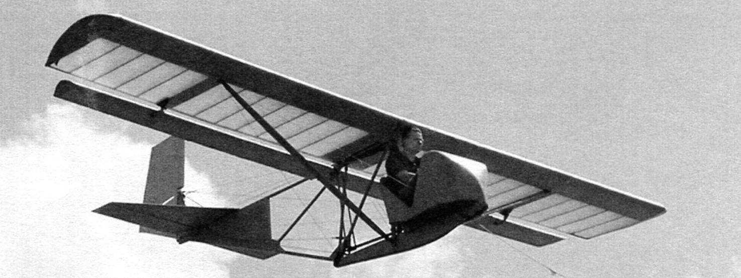
Under “aircraft Schools” and according to numerous requests from readers, the editors have prepared an extensive material about the structure of BRO-11M and technology of its manufacture.
 
So, Bro-11M is a strut-braced high-wing monoplane with all-wood construction with truss fuselage.
 
THE WING AND AILERONS
 
Wing glider has a very simple and typical for gliders 1930-ies the design, which can be used as a basis for independent design and construction similar in purpose aircraft. This is confirmed not only by the work of B. I. Oscines author of several gliders initial training with this wing, but also the development of many aviation enthusiasts, built on the model and likeness of BRO-11M gliders, motor gliders and airplanes.
 
Of course, each case should take account of the rules strength – wing, which explains designed only to operate it on BRO-11M; in case it is installed on, say, a light aircraft wing must be converted to strength and, if necessary, to strengthen its main elements.
Wing BRO-11M consists of two symmetrical polycrylic solid wood construction, which are attached to the farm of the fuselage for the root of the rear spar and stringer. Each half-wing that is fixed by the strut, the upper end fixed on the middle part of the spar and the lower farm of the fuselage.
 
The set of each wing includes a box-spar, 17 ribs, front and rear stringers end of the arc, plywood paneling, knize and lugs. Some metal units are mounted on the wing frame to its Assembly (spar and ribs) and the rest to install on an already assembled frame.
 
Geometric pattern glider BRO-11M design B. I. Oscines
 
Geometric pattern glider BRO-11M design B. I. Oscines
 
The overall design of glider BRO-11M
 
The overall design of glider BRO-11M:
 
A – tow hook and the front rubber stop mounted on the farm of the fuselage with bolts M8; B – upper attachment point of strut-to-wing attachment lugs and stretch marks; – the airlock of the wing spars and the vertical posts of the farm (M8 bolts, pads of 4 mm sheet of aluminum; G – pendant ailerons and the mounting clips for the wiring cables of the Elevator control; D – lower-ear brace stabilizer linkage and rudder; E – rocker roller for the transaction control cable elevators and the rudder linkage; Rail safety emphasis on wing of duplicated rubber with a thickness of 15 mm; And – the mechanism for controlling the ailerons (using two vertical tubular rods) and elevators (with duplica rocking and cables)

 
Half-wing design of glider BRO-11M (right hand shown, left - reflected view)
 
The wing design of glider BRO-11M (right hand shown, left – reflected view)
 
The design of the Aileron (right hand shown, left - reflected view)
 
The design of the Aileron (right hand shown, left – reflected view)
 
Rib of the wing and Aileron, vzaimoponimanie wing and Aileron
 
Rib of the wing and Aileron, vzaimoponimanie wing and Aileron
 
The ribs of the wing and Aileron, vzaimoponimanie wing and Aileron
 
The coordinates of the profile of the wing P-II-14%
 
The coordinates of the profile of the Aileron P-III-16%
 
BRO-11M before takeoff
 
BRO-11M before takeoff
 
Lock shank braces and rear wall of the wing mounted on the rear stringer after the Assembly of the wing with two bolts and nuts М6х32. Mounting area reinforced with plywood plates and ash strap section 34×8 mm.
 
Castle braces reinforced with three steel pistons with a diameter of 4 -6 mm. Hinged hook lock hinge bolt fixed M6 that has been cut and installed between the two washers. Castle secondrun roller in the lower end of which is mounted a locking pin, bent wire, allied with a diameter of 1 mm.
 
The wing spar consists of two solid pine shelves with a cross section of 20×10 mm, reinforced Podlasie strips of a cross section of 10×10 mm and three bosses, fourteen pillars and two end rails. Spar after Assembly, carefully processed jointer and glued with two sides of 1 mm plywood. The root part of the spar in place of the attachment to the fuselage is reinforced with labels from 1 mm plywood size 65×24 mm. the unit consists of two 1.5 mm plates D16T, remove the caps from the pipe marks 20A with a diameter of 8 -10 mm. In the middle part of the spar is reinforced with slats section 12×5 mm and a length of 135 mm, pasted on both shelves, and with plates of 1-mm plywood size 135×54 mm. In the same place between the ribs # 9 and # 10 is the attachment of the wing strut that is welded from a steel plate, two necks and sleeves.
 
And a strut connecting the nodes are fixed by bolts M5 x 21 with washers and castellated nuts. The roller is intended for joining the wing to the fuselage.
 
Profiles of the wing and the Aileron shown in the table control sections (both have a positive twist of about 2 degrees, increasing the wing efficiency at high angles of attack (stall occurs first in the middle of the wing). The necessary twist to get a slight bend of the spar in the stocks in front of the paneling and the frontal part of the wing with plywood after this operation, the wing will retain the desired twist.
 
All ribs have the same profile and chord, but different in design. So, ribs No. 2 to No. 9 and No. 11 – No. 14 I-beam section, is assembled on the glue and the nails of the four strips cross-section of 5×5 mm, two bosses and walls made of 1 mm plywood with holes for their relief.
 
The root rib has a reinforced box section design. Her shelves are glued rails 12×5 mm. cross-section of the Strut adjacent to the holes for the spars are the cross-section 12×10 mm, the remaining struts and bracing – 12×5 mm. In walls the front of the rib holes cut for ventilation. Reinforced rib No. 10 and No. 15 are similar in construction with rib # 1 and have the same cross-section reek.
To the shank rib No. 10 bottom glued boss size 185x52x14 mm. Shank and boss pasted over with two parties a 1.5 mm plywood size 210×94 mm, over which are glued two strips cross-section of 10×8 mm and length 185 mm. lug To the three M5 bolts attached to the bracket of the Aileron, cut from 3 mm sheet D16T with a thickness of 3 mm. Into the eyelet of the bracket is inserted and over-rolled steel sleeve with a diameter 8×1 mm. Shank rib No. 16 has a similar structure, only the boss is designed to protect the wing tips from hitting the ground.
 
The ailerons are suspended under the wings on two hinges, one located on the farm of the fuselage and the other on the bracket rib No. 10. An unusually large wingspan outboard of the ailerons, almost equal to the wing span, ensures their high efficiency.
 
The frame of the Aileron consists of a spar, the same sixteen ribs, the front and rear stringers and panels and brackets. The ribs in the set are located at the same distances from the plane of symmetry of the glider, and ribs of the wing.
 
Each of the side members consists of a pine plank section 55×8 mm with three bilateral enhancing stickers. Reinforced the Aileron rib # 1 is from pine slats with a cross-section 55×6 mm, length 315 mm, covered with 1 mm plywood: exterior – along the entire length, inside – 122 mm, measured from the toe of the sock rib.
 
Reinforced rib number 10 is assembled from two shelves section 7×5 mm, two brackets in the toe with a boss between them, plywood walls, small knize at the end, but also bosses and knize in the middle of the ribs for mounting hinge of the Aileron. Design normal rib the same as rib No. 10, except that the average boss with cnica do not exist.
 
The horn of the Aileron with the ear of the root hinge is made from sheet 2 mm of aluminum. At the bottom of the hole diameter of 8.1 mm seamed sleeves from steel pipe with a diameter 8×1 mm. Hog is attached to the outside of rib No. 1 three M6 bolts with a length of 20 mm. the Two same bolts mounted on the rib No. 10 bracket of the Aileron.
 
THE WING STRUTS
 
The wing struts are made of pine blanks, each of which is to prevent warping glued with epoxy two strips of cross-section 85×20 mm. Planks should be smooth, without knots, rot, and ROE. After the gluing of the workpiece treated using contraband in accordance with the sections of the brace depicted in his drawing.
 
The terminal parts of the struts of the pyramidal shape. After pasting these sections fiberglass with epoxy resin on them nasazhivajut upper and lower ferrules, welded from sheet steel St. 20, and attach them to the strut bolts with M6 thread. The upper end of the strut is fixed by M8 bolts and castellated nuts on the lug mounted on the wing spar near rib No. 10, and the lower node to the front of the farm of the fuselage. After installation of castellated nuts be sure spletayutsya.
 
From the top of the tip cable brace run brace to the front of the farm of the fuselage and tail feathers.
 
The ends of the cables are braided in shackles or sealed copper tube. The necessary tension of the braces is carried out by the turnbuckles with a length of 100 – 150 mm with thread not less than M5.
 
The turnbuckles counter the mild steel wire with a diameter of 1 mm.
 
TAIL
 
The tail Assembly consists of fixed elements (stabilizer and fin) and movable (rudder and elevators). Kiel, docked with the stabilizer of a pair of tubular struts, the ends of which are sealed, U-shaped staples.
 
The stabilizer is of a triangular shape. Frame it is made up of spar, seven ribs and front ribs, four bosses and 32 brackets. The spar is made from pine slats with a cross section of 35×5 mm plywood sticker (amplifier) in the middle part. To the rear of the spar glued four strips cross-section 10×7 mm. Reinforcing the spar, they also serve to reduce the width of the gap between the stabilizer and elevators. Rib No. 1 (middle) and 5 (oblique) made of pine slats. Node, used to mount the strut and hinge the elevators, made of sheet 2 mm duralumin D16T .
 
The rudder (in the same way as the blades of the Elevator) has a wooden frame with fabric cording. Gather these elements of the airframe is almost the same as the wing and ailerons. When coating surfaces with dope is recommended to fix them with clamps on a thick Board to prevent warping.
 
COVER THE WING AND AILERONS
 
Cording to the frame of the wing and Aileron fabric -a very important operation, the quality of which depends on the aerodynamics of the airframe as a whole. Preparations for this operation is a thorough cleanup with a file and sandpaper surfaces all parts of the frame that will be joined to the fabric.
 
The best material for stitched – aviation percale, but find it now difficult. However, it is possible to fit the glider sateen or chintz. Close-fitting, it is desirable to produce a single piece of fabric or make the workpiece with a minimum number of seams.
 
The thus prepared fabric is superimposed on the pre-coated glue frame-it is desirable to use nitrokey AK-20 or dope the first coating. You must make sure that the fabric has been pressed well to all elements of the frame and uniformly stretched.
 
Flash stitched wing (Aileron) on the ribs
 
Firmware stitched wing (Aileron) on the ribs
 
It is particularly important to achieve a proper fit to the plywood leading edge of the wing.
 
After drying, glue the cording is stitched through the ribs thread type “mokey” (and fit more modern Mylar thread) using a special long needle, after which the joints by means of Amalita pasted herringbone tape – strips of fabric with scalloped edges; this operation is necessary in order to prevent peeling of the fabric from the frame while operating the glider.
 
Further surface treatment is coating dope for uniform and strong tensioning of the fabric and make it waterproof. The wing is covered with Amalita in two or three layers with midplains drying and processing of small skin to destroy small bumps and specks. To apply varnish, use a spray bottle (or at least a wide soft brush, without pressure on the fabric). Final painting of the wing runs nitro with high coverage in two or three layers. The last coating is a colourless nitrocellulose lacquer to further Polish automotive “Polish”.
 
The FUSELAGE
 
With regard to BRO-11M name is purely conventional, because of the fuselage as such, this aircraft no. Instead, the glider has a flat power farm of pine sticks, to which bottom is attached to the nacelle with landing fixtures (wheel chassis 250×125 mm and damping of the ski), the pilot seat with poluobechaek, right and left of the farm wing with ailerons, and the rear empennage. The joining of all these elements is well thought out and allows you to quickly assemble and disassemble the glider.
 
The layout of the fuselage of glider BRO-11M
 
The layout of the fuselage of glider BRO-11M:
 
And – belts: 1 – shoulder straps; 2 waist straps; 3 – lock; B – longitudinal beam farm (gluing of pine bars with section 20×30); – the docking station with the use of reinforcing plywood brackets; G is the top node of the hinge of the rudder; D, the lower node of the hinge of the rudder (steel, sheet s1,5); E – the main strut; W – cross section rear braces of the farm; And – the section of the front brace of the farm; – the docking station: 1 – cheek mount tail farm of a fuselage; 2 – the landing shock absorbing ski; L – mount wheel chassis: 1 – top panel gondola (plywood s3); 2 – side wall gondola variable thickness (plywood under s20 wheel brackets to aft thickness gradually decreases to s15); 3 – rail gondolas (pine, rail 20 X20); 4 – bracket (steel, sheet s5); 5 – wheel chassis 250×25; M – node pumping units manual control: 1 – control rod ailerons and elevators; 2 rocking control the ailerons; 3 – rocking the Elevator control; N – lower handle Assembly control: 1 – pipe 20×2,5; 2 – plug; 3 – dry u-joint

 
The design of the gondola fuselage of glider BRO-11M
 
The design of the gondola fuselage of glider BRO-11M
A gondola of the fuselage of glider BRO-11M:
 
1 – towing hook; 2 – shock absorbing landing ski; 3 – duct nacelle; 4 – pedals control rudder; 5 – paleobotanical; 6 – handle the ailerons and elevators; 7 – cockpit; 8 – the pilot seat; 9 – main rack of the farm of the fuselage; 10 – drive cables of the rudder; 11 – control rod ailerons and elevators; 12 – rocking control the ailerons; 13-control rod Aileron; 14-block rocking of the Elevator control; 15-the turnbuckles ropes of the Elevator control; 16-control cables, elevators; 17 – the lower tail stretching; 18 – the outline of the farm of the fuselage; 19 – a connecting node of the farm and gondola
 
B – pedals control rudder:
 
1 – pedal (ash, Board s25); 2 – earring (steel, sheet s1,5); 3 – control cables, rudder; 4 – clamp the pedals to the boss base
 
In the control stick the ailerons and elevators:
 
1 – head handle; 2 – handle (steel pipe 20×2,5); 3 – axis plug tie rod (bolt with M6 thread); 4 – axis rusk (bolt with M6 thread); 5 – holder; 6 – tie-rod; 7 – control rod Aileron; 8 – bellcrank Aileron control; 9 – threaded shank of the tie rod that attaches it to the block rocking the Elevator control; 10 – rocking; 11 – bracket units; 12 – stand; 13 – brace (steel pipe with a diameter of 12×1)
 
P – node mounts in the center column and brace to the side wall of the gondola:
 
1 – dry; 2 – clip (steel, sheet s5); 3 — plate and nuts mounted in the box of the gondola
 
P – node mounts to the gondola roller wiring control cable the rudder

 
Gondola is a box is a streamlined shape having a frame made of pine sticks with working plywood covering of variable thickness. In the middle of the gondola -a niche for gear wheels. At the front tow hook and shock absorbing device consisting of a metal skis, suspension ring made of dense rubber. The same ski mounted and at the rear of the gondola.
 
THE CENTRAL STRUT OF THE FARM OF THE FUSELAGE
 
The Central strut of the farm of the fuselage is welded from steel (grade St.20) of tubes with a diameter of 25 mm. of the Upper jumper strut – of 5-mm steel strips, welded tight continuous weld to the pipe stand and Shoe mount farm.
 
TAIL FARM
 
Tail farm is glued together with epoxy glue from pine slats with a cross-section 30×15 mm and 30×20 mm. Rear (triangular) part of a farm lined both sides with 1 mm plywood, thus forming a large keel surface, which significantly reduce the size of the actual keel, which is BRO-11M is practically used only for attachment of the rudder. In the upper and lower intermediate nodes in the farm are installed a reinforcing boss, covered on two sides by gussets of 5-mm plywood.
 
Front farm node is docked with the Shoe upright using M8 screws, the bottom is the same bolt with cheeks on the rear tip of the nacelle. Upper intermediate node carries the bracket and rollers Aileron wiring cables of the rudder. The top node of the keel serves to attach the upper hinge of the rudder, tail braces and the fork ends of the struts of the stabilizer. The last bent of the 1.5-mm sheet steel (dimensions of the workpiece – 114×70 mm). In the holes for the hinge Ushkov rudder and struts seamed sleeves from steel pipe with a diameter 8×1 mm. the Lower hinge of the rudder is bent from steel plate with dimensions mm 84×45; his ear also zavalova bushing pipe diameter 8×1 mm.
The seat installed in the front part of the nacelle; at the front it is closed with a light poluobechaek of the 1.5 mm plywood, the frame is mounted on two temples. Himself a semi-fairing mounted on the base of the gondola with glue and screws; on the rear edge of it also fixed a couple dural corners with a flange thickness of 3 mm.
 
The seat and backrest are made integral from 4 mm plywood; the base of the gondolas, the seat is attached with glue and screws. The seat and headrest are covered with foam rubber and covered with artificial leather.
 
Seat belts – type lightweight, with cone lock, contrawise spring pin (wire OVS with a diameter of 2 mm). Straps fixed on the middle crosspiece of the Central rack.
 
Pedal foot control is made of ash blanks; control cables, fasten them using the flat of earrings from a 1.5 mm sheet steel.
 
THE CONTROL SYSTEM OF THE AIRFRAME
 
Glider BRO-11M can make maneuvers on the course, roll and pitch using the hand-held control unit. The first is the handle of the pilot associated with the ailerons and elevators, a second pedal connected with the rudder.
 
Scheme manual (left) and foot (right) control
 
Diagram manual (left) and foot (right) control

 
The strut of the wing and its parts
 
The strut of the wing and its details:
 
A – basic dimensions of the strut; B – cross section of the strut; The strut parts (material – St.20)

 
All these items are exceptionally simple in design, easy for Assembly and disassembly and for adjustment. All nodes of the system controls are grouped on the farm of the fuselage, which is very convenient in the operation and repair of the apparatus.
 
THE NODE OF THE ROCKING OF THE ELEVATOR CONTROL
 
The node of the rocking of the Elevator control is a feature of the design of BRO-11 M. During the movement of the control stick to failure “on” simultaneously with the deflection of the elevators up both Aileron deflected down 10 degrees thanks to the original kinematics of the management node, allowing the glider to actively reach the landing angles without clear “tease” of the nose, which allows the landing of the glider is exceptionally simple – usually without the “goats” and usmiani.
 
ASSEMBLY OF THE AIRFRAME
 
The first Assembly of the airframe should be done in bright room size not less than 10×8 m, previously on the floor depicting the basic coordinates of BRO-11 M – axis line (trace of the plane of symmetry of the device), the location of wing and tail. Exactly in the plane of symmetry of the tightened wire, on which the thin filaments are suspended several small weights-weights, designed for accurate installation polycrylic and tail, as well as to eliminate distortions of Assembly parts and units.
 
The gondola must be secured to the floor using temporary bosses and props, and then mounting the rear of the farm and polycrylic. For this operation you will need to do a couple of trestles, with which the Assembly is carried out quickly and accurately.
 
Tail glider
 
The tail of the glider:
A – horizontal tail:
 
1 – stabilizer; 2 – Elevator;
 
B – rudder

 
To achieve the correct geometric shape of the airframe can be uniform tension on the rope stretching.
 
Note that when zaplatka cables may need to define more precisely their length so that the early Assembly of the threaded shanks of the turnbuckles it would be possible to wrap manually, without resorting to the use of the knob.
 
After installing all the stretch marks and uniform tension to the tender can proceed to installation of the cables of the Elevator control and the rudder – they are tensioned not too tight, but without sagging.
 
After covering the cables, the turnbuckles counter the soft steel wire. Correct adjustment of the wires going to the steering wheel the direction of its neutral position should correspond to the neutral position of pedals. The same symptom just and when you adjust the rudder, that is, the neutral position of the elevators the position of the control stick of the glider must also be neutral.
 
The ailerons are correct and accurate in their manufacture adjustment is almost not needed.
 
Flight characteristics of the glider BRO-11M
 
Wingspan, mm………………………………….7800
Length, mm…………………………………………….5470
Height in the Parking lot, mm………………………….2500
Wing chord, mm…………………………………..1450
Wing area, m2……………………………….11,8
Lengthening of a wing…………………………………….6,0
Angle poperechnogo V-wing, hail……………..3
The magnitude of the Aileron, mm……………………………….3650
The area of the Aileron, m2………………………………1,2
The shoulder of the Aileron, mm………………………………..1850
Fuselage length with the beam, mm………………4520
The truss height of the fuselage, mm……………….1240
Maximum width of fuselage mm……510
The scope of the horizontal tail, mm….2200
The area of the horizontal tail, of 1.43 m2.
Area of rudder in m2……………………..0,71
Shoulder horizontal tail, mm…..1820
The height of the vertical stabilizer, mm…….2130
Vertical plane area, m2 …..1,43
The area of the rudder, m2……………..0,71
The shoulder of the vertical stabilizer, mm………2140
The mass of the glider with equipment, kg………….65
Useful load, kg………………………………60
Flight weight, kg………………………………….125
Specific load, kg/ m2………………………..1,8
Maximum quality……………………………12
The minimum rate of descent m/s……….1
Cruising speed, km/h………………………40
Landing speed, km/h……………………….30


G. MALINOWSKI

Recommend to read

  • ON THE WAVES – “MOTH”ON THE WAVES – “MOTH”
    Ultralight Dinghy international class "Moth" "the Moth" (Fig. 1, 2) simple in design, convenient in construction and possesses all the essential qualities of sports ships - fast,...
  • IN FLIGHT — JUST LIKE A REAL…IN FLIGHT — JUST LIKE A REAL…
    Control line model plane-vysokoplan. The first simplest kordovye model. made of pair plates, quickly bored novice modelers — they, of course, want to raise in the air like a real...