 (Continued. Beginning at No. 10 in 1975.)
 TO ENSURE THE SMOOTH PROGRESS AND SUSTAINABILITY
This task is more difficult than a lighter car. There are examples where Amateur designers created the suspension of a small car accidental selection of the finished parts and the result was a hard, Bouncing ia insignificant rough roads, bad listen to steering the car. Meanwhile, considering some of the theories and to use the experience of designing “real” cars, it is possible to achieve good smoothness and stability.
First of all, you select the schema of the suspension. Its kinematics (the movement of individual units and the corresponding movement of the wheels) should contribute to the stability of the vehicle. The kinematics of the front suspension, you also need to coordinate with the steering control scheme (see article fifth), and the kinematics of the rear with the device rear axle. At the same time define the type of element spring suspension — leaf springs, coil springs, twist rods (torsion bars), rubber blocks. Then the stiffness of the suspension. While taking into account the stiffness of the tires, primarily the internal pressure in their cells, the magnitude of friction in the selected suspension system. Finally, set the suspension and, if necessary, stabilizers lateral stability.
The main guarantee of stability (in addition to rational distribution of mass on the wheels and low centre of gravity) that the car had a so-called “understeer”. This means that the centrifugal force of the turn, a gust of side wind or slope of the road cause greater slip of the front wheels than the rear: this prevents excessive sharp turns, and the occurrence of drift. To reduce this factor need (along with a reduction in tyre pressure the front wheels to the allowable conditions of load limit or increase the pressure in the rear) to arrange the suspension so that when it is working, the front wheels are moved in planes approximately parallel to the plane of symmetry of the body, and back bent against the body (Fig. 1). This condition is responsible front independent suspension with trailing arms (“Zaporozhets”), with a transverse oscillating “parallelograms” (“Zhiguli”, “Moskvich”, “Volga”) and the so-called “candlestick” rear suspension with a rigid axle or swinging on a single hinge axis. If each of two axle joint (“Zaporozhets”), shall be provided transverse or angled levers, a swing which provides the desired inclination of the wheels. Such suspension shown in figures 2 and 3 (rear suspension rigid axle on leaf springs or coil springs are well known and therefore not shown). To increase the tilt of the front wheels after the roll body upper wishbone parallelogram suspension” in short, make the bottom (Fig. 4).
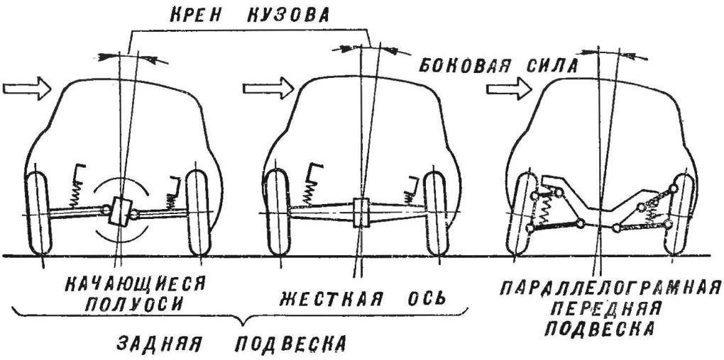
Fig. 1. The recommended scheme suspensions.
Rear suspension cargo scooter (motorized wheelchair)
The rear suspension of the car ZAZ.
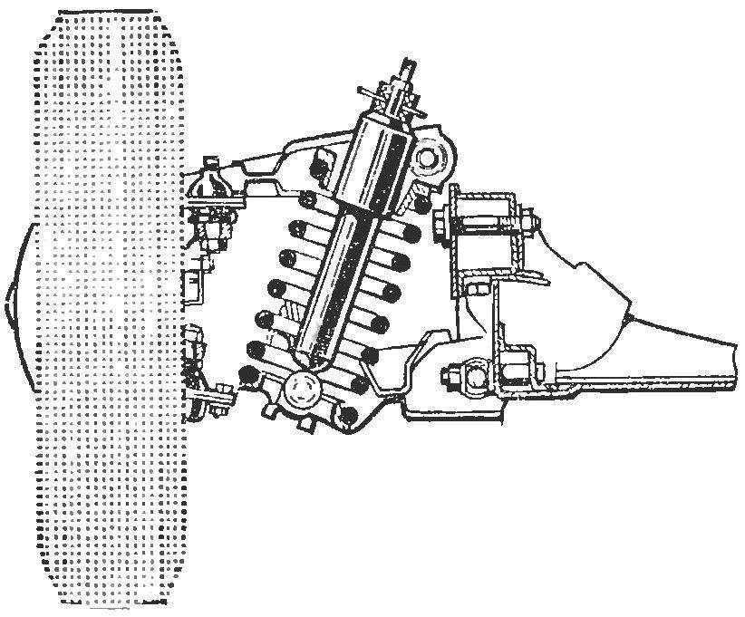
The front suspension of the car VAZ.
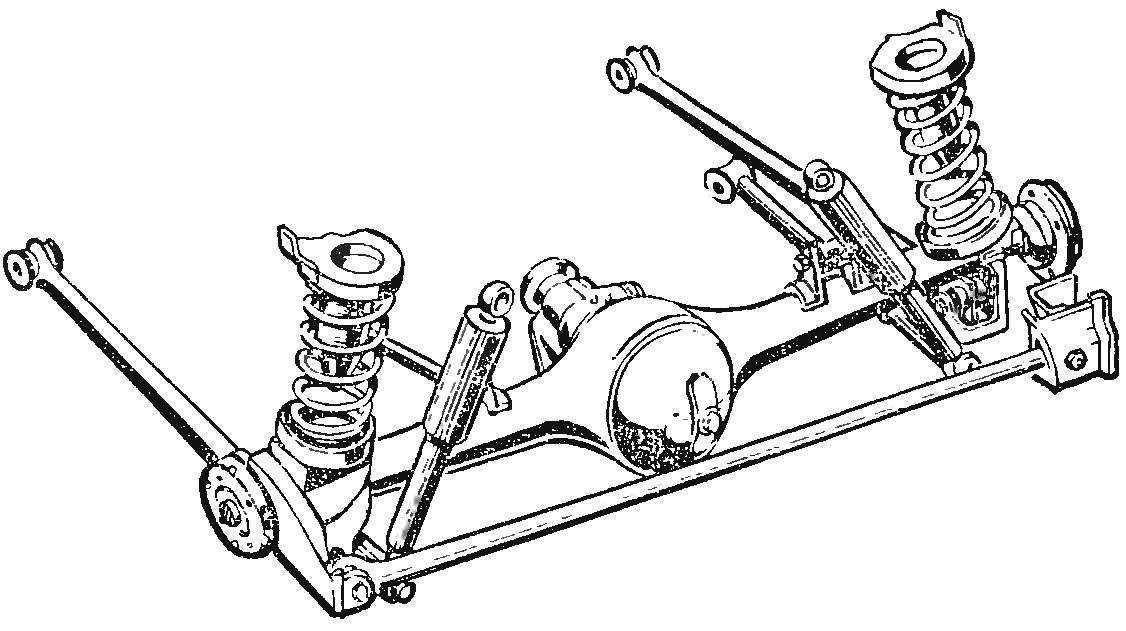
The rear suspension of the car VAZ.
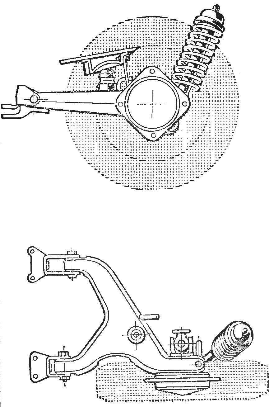
Fig. 2. The most common design of the spring suspensions.
Swinging levers attached in the form of a triangle to pass to the frame or integral body pushing and braking forces acting in the longitudinal direction.
Suspension movement up is selected so that the contact bridge or rocker arm with the sprung parts of the car was possible only under the load of spring (spring) in half to two times greater than normal. Suspension travel down to accept the same or somewhat larger. Limit switches serve to set the frame, body or suspension arms rubber buffer.
The point of attachment of hangers to the beam, frame or body is better positioned as high as possible; this is achieved by reducing the body roll on the turn. High mounts and the installation of telescopic shock absorbers under large inclination allow you to do without a stabilizer bar.
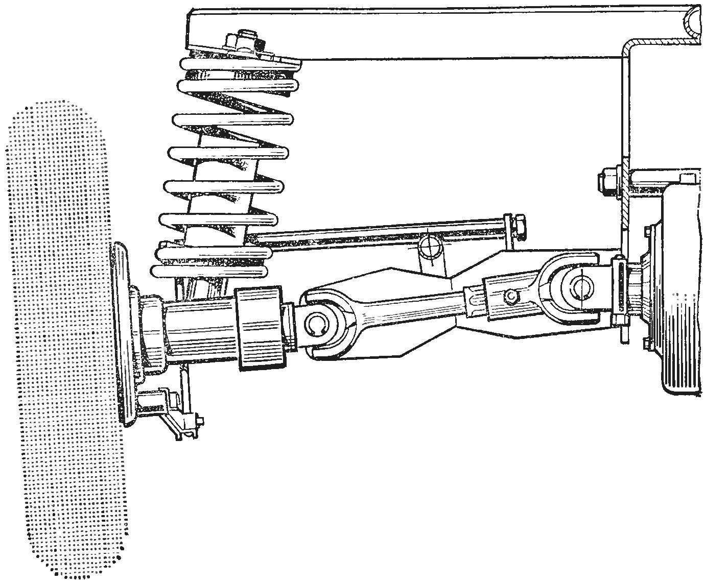
Using longitudinal rocking levers, the designers take into account that when such a front suspension can change the tilt of the king pin. So make either two levers (“parallelogram”), or set a large angle of pivot back (to 22°). In the rear suspension with trailing arms last bet, as already noted, is parallel to the axis of symmetry of the body, and at a certain angle to provide the necessary tilting of the wheels and the perception of pushing, braking and lateral forces. If the axis of the swing arm passes through the center of the joint (cardan) axis, it is possible to install one, not two hinges (Fig. 5).
To reduce tire wear and improve vehicle stability is very important precise setting of the wheels, keeping this setup for a long time and a minimal change in the gauge when working the suspension. Front suspension it is advisable to mount the beam on a special, well-adjusted, and then together with the beam fastened to the frame or body. The adjustment is made with shims at the attachment points of the rocker levers. Developing a drawing of the kinematics of the suspension, you should pay attention to possible smaller deviations of the wheels of the nominal value of the gauge. Usually there is a need to reduce the suspension stroke.
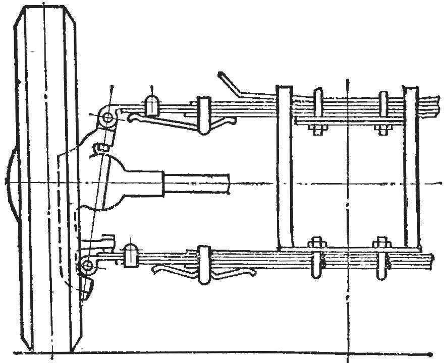
Fig. 3. Suspension with transverse leaf springs.
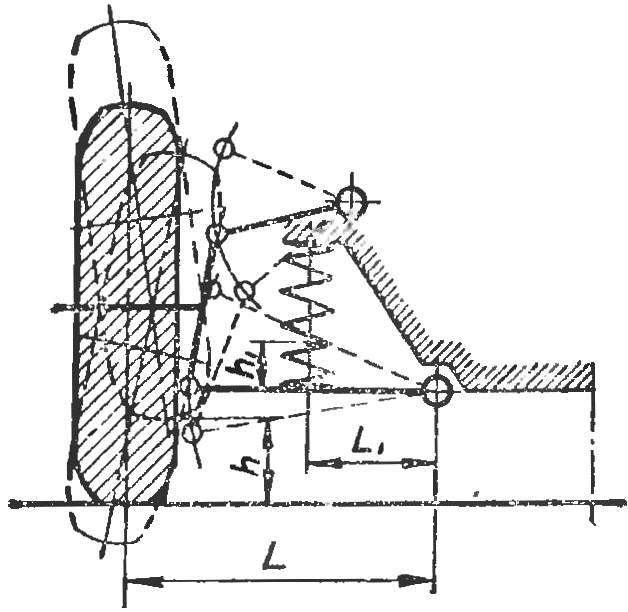
Fig. 4. Diagram of the parallelogram of the suspension.
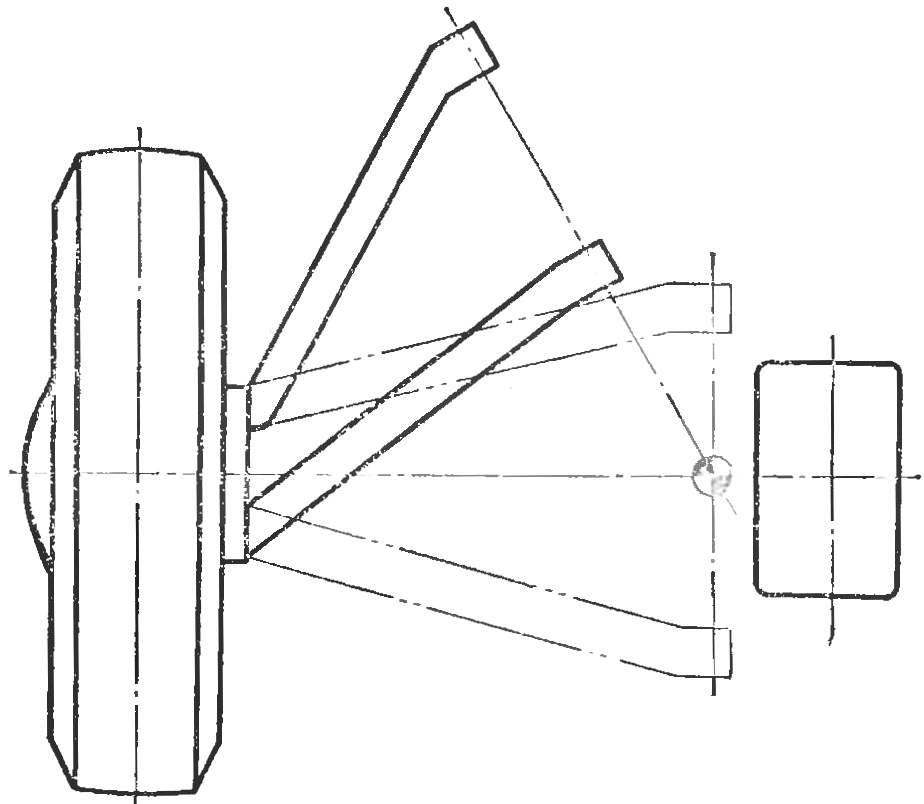
Fig. 5. Suspension with the axis of the swing arm
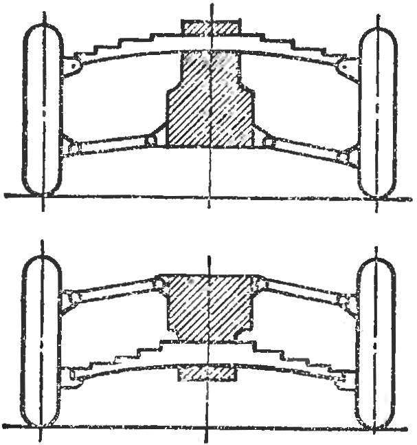
Fig. 6. Suspension with single transverse leaf spring.
It is widely believed that different types of spring elements have different stiffness. This is inaccurate. And the sheet springs, springs, torsion bars, and rubber blocks to give the required stiffness, for example, to decrease the elongation of the spring or torsion bar, etc. So they choose solely on the basis of constructive and technological considerations: what materials are available to the Builder that it is easier to manufacture and easier to place in the car. Most suitable for self-avtostroitel spring elements are coil springs and leaf springs. High quality torsion bars are difficult to manufacture; their use can be justified when using finished parts (front suspension sidecar or “plows”), it’s also Hard to pick up working in compression or torsion rubber blocks to prevent their aging and changing in the process of operation.
Hardly Amateur avtostroitel will produce all the rules of calculation of the suspension. But he should at least experimentally to verify its characteristics, before you put on the car.
The stiffness of the suspension is determined by the number of pounds required to compress 1 cm given the fact that the rear wheel usually Has a higher load than the front, the stiffness of the rear suspension of the micro-car, only choose is 35— 60 kg/SGL and front — 25-35 kg/cm.
With some approximation, the stiffness of the leaf springs themselves can be considered equal to the rigidity of the suspension as a whole. Loading the spring while experience of falling on her part of the estimated mass of the vehicle and measuring its deflection, check the rigidity. If necessary, add or remove leaves.
Cross-spring — usually dwuhpuchkova, longitudinal can be odnoosnovny. The second sheet needs to be extended to the entire length of the spring and may even partially cover the ears. While independent suspension is usually applied two cross-spring or single and swinging the levers at the top or bottom (Fig. 6), and for the rear suspension that Tina required longitudinal or angled torque rods for the transmission of pushing efforts.
The length of the rear longitudinal leaf springs is usually 40-45% of the length of the base, transverse make possible longer and within the wheel track. The width of the leaf springs for a small car of 40-50 mm, the thickness of the main sheet of about 5 mm. Spring from many thin sheets softer than the springs of a few thick.
The stiffness of the coil spring may be equated to stiffness, in General, in the case of “candle” suspension or when the spring rests on the end of the lever. In fact, the spring pulls the lever in its middle part. If the wheel rises to h mm (see Fig. 4), the lower turn of the spring will rise less than, namely, h1 = hl1/l mm. the wheel Lift occurs under the action of a force P, and the spring is compressed by a force P1, which is < R, i.e. (P1 = P1/l1).
Spring must be correspondingly more stringent. If you are unable to make or pick up a desired spring stiffness, it is possible to put the two springs, as was done, for example, in the rear suspension sidecar С3А.
The springs and spring made of steel 65G with a permissible limit of tensile strength of 75 kg/mm2 and a yield point of 40 kg/mm2.
The suspension arms are made of steel pipes, profiles, sheet metal and forgings. These parts must meet the same requirements for material and heat treatment, and parts of the steering gear (see article fifth). Levers mounted on textolite or rubber bushings. The latter is particularly appropriate, as it does not require lubrication and soften horizontal tremors that occur due to the small size of the wheels.
For the rear suspension will fit longitudinal flexible arms in the form of plates (“Volkswagen”), allowing the rod by one hinge.
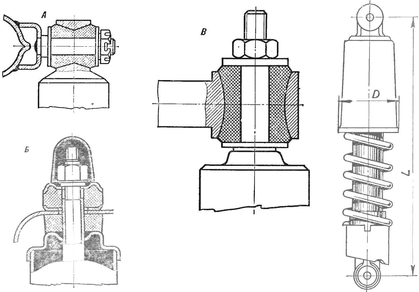
Fig. 7. Types of upper lugs and the size of the dampers and motorcycle suspensions (see table).
From industrial shock absorbers suitable shock absorbers from sidecars, cars “Zaporozhets”, “Zhiguli” and “Muscovite”; sometimes, to relieve excessive rigidity, regulate it. When spring suspension the damping force is within acceptable limits, if their compression is necessary to force 15-20 kg for end — 70-80 kg. If the suspension on the leaf springs or plate-like torsion bar having a large friction, the magnitude of the effort to end should be half-half. The shock absorbers play a very important role in enhancing vehicle stability. Therefore, it is permissible to neglect are too high for some inputs to directly affect the mass of the absorbers are taken from a relatively large machines of mass production.
The simplest solution of suspension design — mounting instead of the coil springs motorcycle suspensions, which combine the shock absorber and coil spring. The principal dimensions of dampers and motorcycle suspensions are given in the table.
THE SIZE OF THE DAMPERS AND MOTORCYCLE SUSPENSIONS

The stiffness of the suspensions may be given less attention if the tire pressure is low. This requires a tire with a relatively large volume chambers. Overall improvement in the characteristics of body vibrations is also achieved with low weight of the unsprung parts. These circumstances should be taken into account when designing the suspension.
Good suspension is needed the car not only for comfort and stability. After shaking the car difficult to control. To avoid a possible loosening of its components and parts on the rough roads to deliver passengers from the shaking, have to drastically reduce speed, expend more fuel. Therefore, the Builder must especially take seriously the designing and manufacturing of the suspension of his future car.
Recommend to read
 GROWERS PITCHER
Ceramic jugs in the village are not uncommon. Apparently because of the cheapness and practicability of vessels of baked clay, in which water almost months remains prohladnenskiy, and... T-MOLDINGS
The gaps between the doors or door leaf and the jamb cover strip, typically of the rack, attaching it with the overlap to the free edge of the door. If the rail is narrow, it is poorly...
