 FROM THE ENGINE TO THE WHEELS
 The transmission from the engine to the wheels can be carried out on a homemade car in different ways. In practice, often such schemes:
a) the power unit of the motorcycle is located in the front, transmission to rear axle (or to the rear wheel when tricycle layout) is the propeller shaft;
b) motor is the same powerplant is located near the rear axle or wheel, transmission chain, motor type (option scheme adopted on Serpukhovskaya the scooter);
C) a motorcycle engine with your transmission or gearbox from the car interlocked through the reduction gear housing, gear; in this case, the “split” rear axle suspension rod (u-joints) and an independent suspension.
In other cases, perhaps the use of different designs of the rear axle. However, the rigid axle at small sizes of the wheels of the little micro-car limit ground clearance and can be recommended only in combination with reduction gears.
The vehicles used usually lightweight open tubular propeller shaft with two joints on needle bearings. To ensure the uniformity of rotation of the driven shaft In (Fig. 1), you need to perform the angle between the leading and the propeller shaft B equal to the angle α1 between the shafts B and C. the Most suitable pipes for cardan shafts — steel, welded, with an internal diameter of 55 mm and a wall thickness of 2-3 mm. For welded to the tube shaft spline lugs take steel with a HRc hardness not less than 35.
To calculate driveline is necessary to determine the maximum moment Mmax in kg·cm, the shaft is passed, according to the formula:
Mmax = M DV ·i0 kg·cm,
M whereDV is the highest motor torque in kg·cm, i0 is the highest gear ratio in the gearbox (or the entire powertrain — axles). Please note that for the axle shaft it is necessary to take the magnitude of this moment, and not its half, as the differential redistribution of effort between the axles.
Getting the value of the torque, it is possible to calculate specific pressure on the splines of the torsion tube. Specific pressure is calculated by the formula:
α = Mmax/((D+D)/4)((D-d)/2)l·n = up to 200 kg/cm2,
where D is the outer diameter of the shaft splines, d — inner diameter of the slots, l is the length of the splines (all dimensions in cm), n is the number of slots.
The torsion pipe is calculated according to the formula:
σ = Mmax/K·S = not more than 1250 kg/cm2,
where S — thickness of wall in mm, and K is a coefficient for pipe with an internal diameter of 25 mm and 1.4; for Ø 35 to 2,3; for Ø 45 to 3.4; for Ø 55 — 5,0.
Splined joint should be protected from dust and dirt covers.
But even very durable, the shaft may collapse if his so-called “critical number” of small RCC. It should exceed the possible highest number of revolutions per minute (when the estimated or actual maximum speed) is not less than 20%.
where D is the tube outer diameter, d — inner diameter, L is the distance between the centers of the universal joints (all dimensions are in cm).
Driveshafts should be ready to take: for a double car — from Kiev and the Irbit motorcycle or its sidecar, to quadruple the car — “Moskvich”, “Zaporozhets” or Vase. Strength welding of pipe-to-fork or slotted end of the torsion is checked with a lever with a load. At the same time (the product of mass of cargo to the length of the lever) needs a half to two times the maximum.
Using motorcycle chain gear, try to put it in terms close to those in which it is designed. If vehicle weight and torque significantly more than the motorcycle, which borrowed the chain, you need to put the two chains.
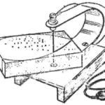
Car with full weight of over 600 kg, according to the requirements of the traffic police, must have reverse gear. As is well known in motorcycle gear boxes (except “Dnepr-MT-10”) it is not, and to incorporate it into the box very difficult. In this case (if you do not use automotive gear box) need to provide a car reversing. One of the reverse chain, used on sidecars. The device of the reverse gear is self-explanatory. The gear ratio of the reverse should be about 1.2 to 1.3, taking into account the movement of the car is included in the transmission first gear.
Of the many possible designs of major bridges will look at five made mostly of finished parts.
Fig. 1. Diagram of driveline.
Fig. 2. Drive axle motorized С3Д.
Fig. 3. Drive axles cargo scooter “Tula-TGA-200” and the car “Zaporozhets”.
Single bridge with double joint suspension rod used on the scooter (Fig. 2). The details of this bridge are designed for the car with the engine IZH and with a full mass (with load) of about 600 kg and under these conditions work quite reliably.
Another option is the bridges of the car “Zaporozhets” (4-seater) and cargo scooter “Tula-TGA-200” (Fig. 3).
In the third embodiment are used: the differential and gearbox of a production car (“Muscovite” or otherwise), the main gear of the same car or a motorcycle (Irbit and Kiev plants); installation of a box of differential of the spur gear requires turning the last fork of universal joints (“Muscovite” and VAZ), brake drum motorcycle (see article fifth). Such a bridge is tested with a loaded weight of about a ton and has proved to be workable. There is only excessive wear of the splines of the half shafts if they are not covered with rubber covers and are not provided with grease. Figure 4 visible welded to the brake shield casing.
Bridge with otnosheniyami axle shafts (the fourth option) require levers or stocking axles, swing axis which passes through the center of the gimbal (see article six). At the same splines on the axle do not need, but you must comply with special accuracy in manufacture and Assembly of parts.
A valid constant angle of the cardan shaft is not more than 7° (preferably fewer), most, in the end position of the shaft — 15-17°. Permitted voltage for parts of semi — 1500-2000 kg/cm2.
The fifth bridge construction is a rigid bridge from the “Moskvich” VAZ or raised above the road with the wheel gears. The use of the latter also allows you to change the overall gear ratio of the transmission, if necessary. Wheel motors need to increase ground clearance and reduce angles of universal joints work with oscillating axles. Examples of wheel gearboxes are available on the car LUAZ-969 and UAZ-469.
Don’t forget to supply the drive wheel hub seals and slingers on that grease falling on the surface of the brake drums and linings.
Reliable front drive axle with swivel wheels is hardly feasible in a small workshop.
The most successful layout of the transmission is obtained when the engine and gearbox in unit with the main gear. Installing between engine, for example, Irbit plant, and the leading axle of the vehicle transmission, it is possible to obtain a suitable length of the power unit behind the rear axle even in the presence of additional gear between the frame and the axle. The reducer may be necessary to raise the engine and box to increase the ground clearance. At the same time a reducer is used if you need to change the overall gear ratio of the transmission, the gear unit serves as a transitional link between the housings of the gearbox and the main gear. Please note the location of spiral bevel gears of the main transmission! When the driving gear is put off, the led must be mounted on the differential box on the right hand side of the car. The correct direction of rotation is located to the left of the driving gear is achieved by two gears in the gearbox. Here it is appropriate to remind that the above-mentioned wheel motors change the direction of rotation of the wheels, which should be accordingly taken into account in the device the entire powertrain.
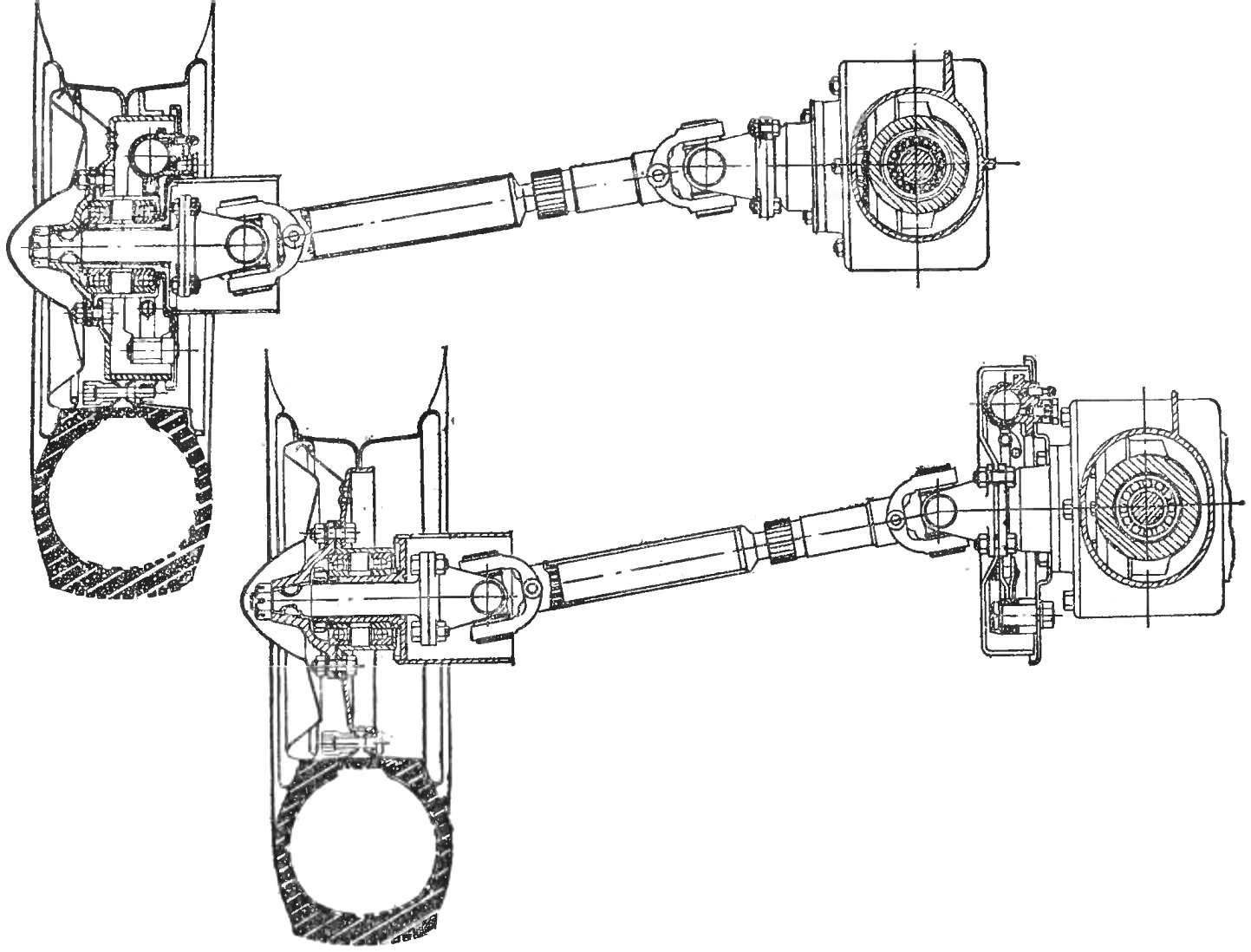
Fig. 4. The drive axle of the nodes is equal to cars and motorcycles; bottom option with the brake drum on the inner end of the axle shaft.
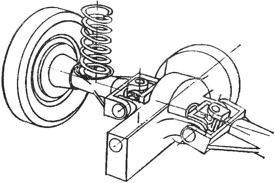
Fig. 5. The swinging axis with one hinge.
Mount the wheel to the brake drum can be performed in different ways: welded to the drum of the so-called “Bonki” on the outer contour on the front surface and screw them to studs, or to surround the drum ring of angular section welded thereto with pins. In the latter case, the size of the disc and the mass of the smallest wheel (see Fig. to article 3).
The drive control change transmission and clutch located at the rear, near the engine, it runs rods, levers or hydraulic drive, the lever gear change mounted on the floor panel. Control carb you can run the cable, with the cable in the shell or without. In the absence of the shell required the rollers with protective brackets.
Amateur designers often attach of all units of the car, not on the host body (as is done on serial cars), and on the frame.
The longitudinal beams of the frame (rails) and cross-beams are made of U-shaped box sections or thin-walled pipes. Material — low carbon steel. Crossmember features in areas of load application — suspension, engine, gearbox, spare wheel and tank. For a small length of micro-car, only enough for four crossbars. The approximate size of the parts of the frame are as follows: for open profiles thickness 4 — 5 mm, wall height is 70-100 mm, flange width 30 to 40 mm; for closed profiles thickness can be reduced to 2-3 mm, height of 50-70 mm; pipe diameter 50-70 mm and a wall thickness of 2-3 mm.
Connect the crossmember (as well as engine mounting brackets, etc.) with the side members by welding or riveting; the rivet diameter is 8 mm. it is Recommended to connect not only the shelf, but also walls of the frame, positioning the holes for the studs are not closer than 20 mm from the edge of the shelves and each other. In the junctions of useful scarves. Their role can play the floor panel, if you fasten it to the corresponding points on the frame. To avoid transverse welds on prodannyh bars of the frame.
We tried to direct the thought of the Builder to the competent and practical solution to the layout and arrangements of a homemade car, in a creative, proactive approach to the design of the machine. We hope that our article will provide construction material to create original and functional cars.
Recommend to read
 THERMOELASTIC FOAM
In our self-similar groups the foam — some of the most popular materials. One day we read in the "M-K" (No. 9, 1977) about the different ways of processing foam. We liked most of the...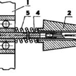 BETTER – COLLET CHUCK
The idea is to expand the capabilities of the lathe for matches, published in the journal "modelist-Konstruktor", arose when it became clear that, first, wood is modern matches...
