
 From the time of this writing I have built five catamarans of various designs. In designing, building and testing these boats took an active part my friend Anatoly Pavlovich Ignatchenko. Not to say that none of them did not satisfy me. A catamaran with inflatable floats performed well on water the Moscow region, and Lower Volga. But Pneumatics poorly kept shape, which significantly reduced the speed. So the idea arose to build a catamaran with rigid floats.
Wooden floats, while simplicity of execution, were rejected. Water and wood, including plywood, are incompatible. And to ensure proper impregnation of wooden parts in a home workshop is not so easy.
Manufacturer of floats made of fiberglass tempting, but difficult. In addition, in the manufacture of fiberglass products require resources respiratory protection, protective clothing and good ventilation.
Hard aluminum alloys, D16, for example, in the manufacture of a covering of the floats hold their shape well, but the leaves are bending without heating to break.
So I opted on the leaves of the more ductile alloys, AMG and AD31, which are well bent. As shown, the choice was made correctly.
The manufacturing process of the catamaran produced in stages: design, preparation of materials, the manufacture of floats, steering and svetovogo devices, masts and sails, standing and running rigging, Assembly and testing.
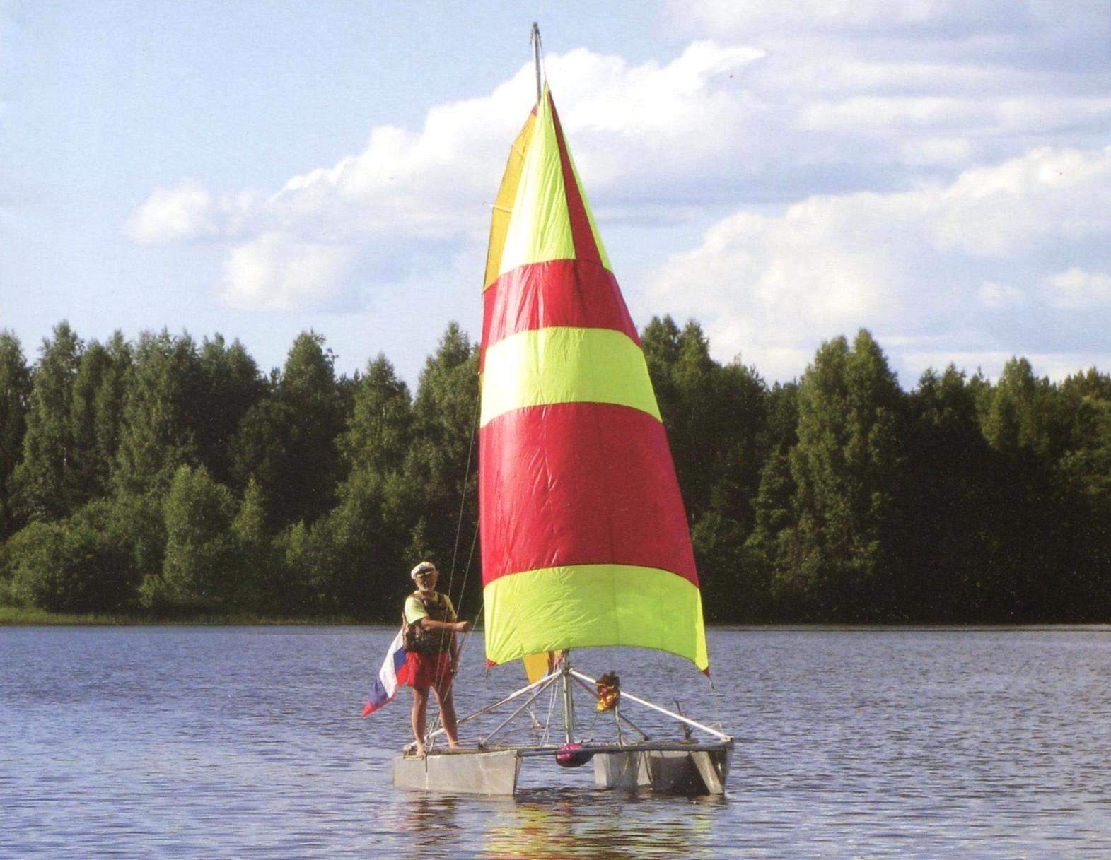
The design began with clarifying the purpose and size of the vessel. Catamaran (subsequently called it “Frisky”) was supposed to use for day trips on the rivers and lakes near the coast with 2 – 3 passengers at low speeds. Note that the catamaran is not recommended for use with wind over 6 m/s and a wave higher than 0,5 m.
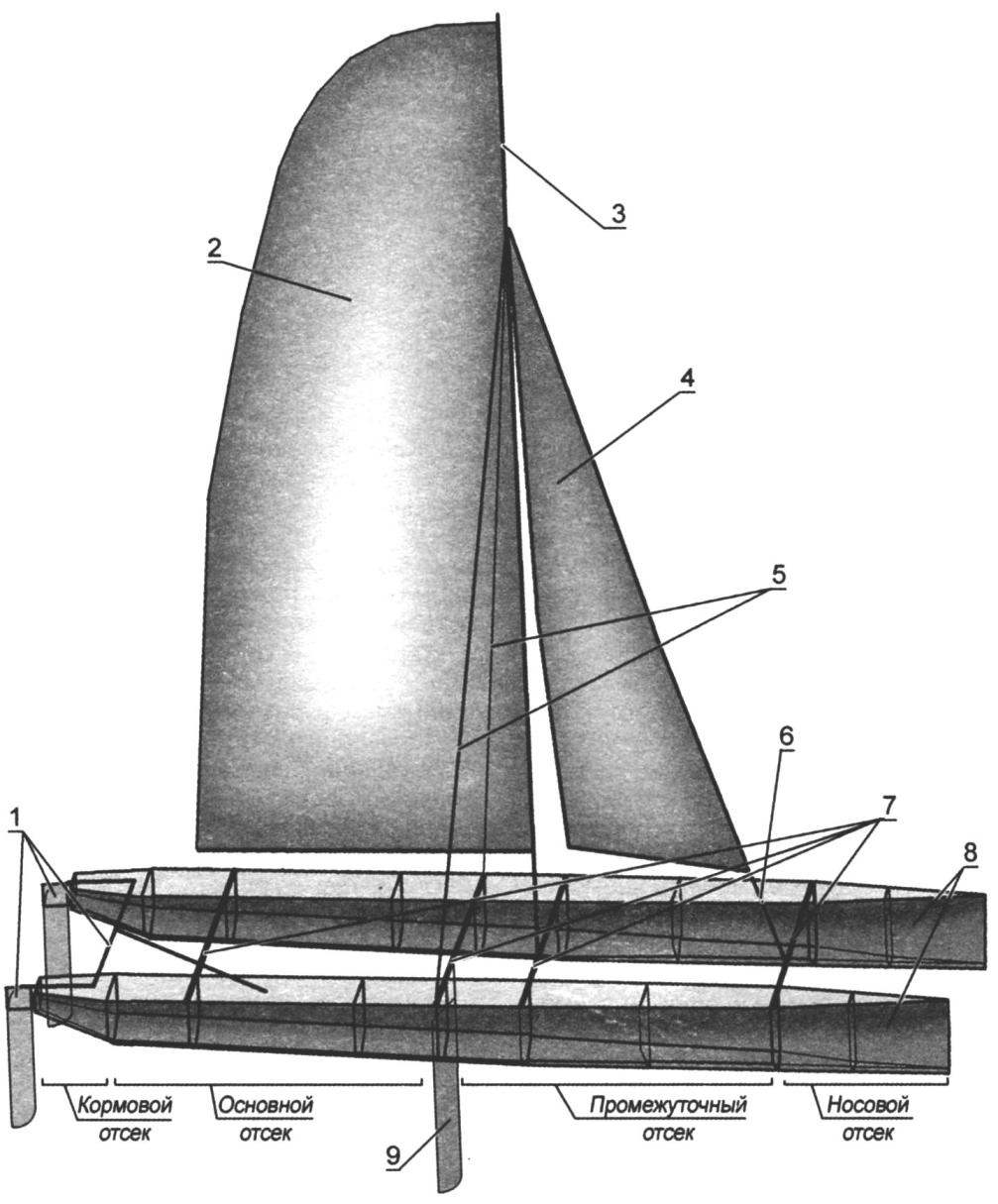
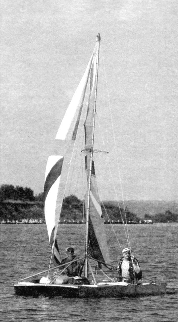
Catamaran “Frisky”:
1 – steering mechanism; 2 – you; 3 – mast; 4 – staysail; 5 – shrouds; 6 – shtag; 7 – beams; 8 – float; 9 – centerboard
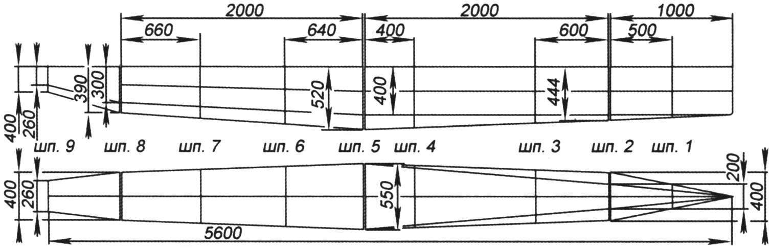
Scheme and main dimensions of the housing of the float
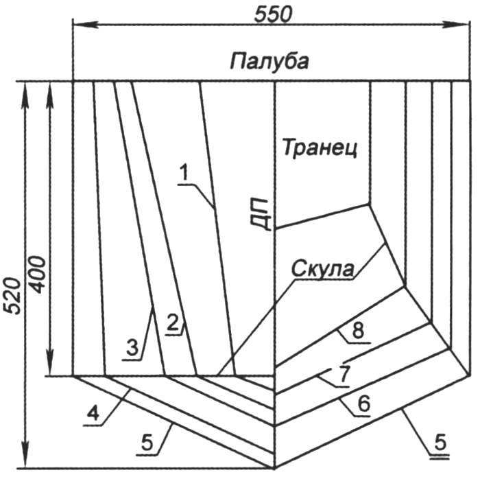
Theoretical projection of “housing”
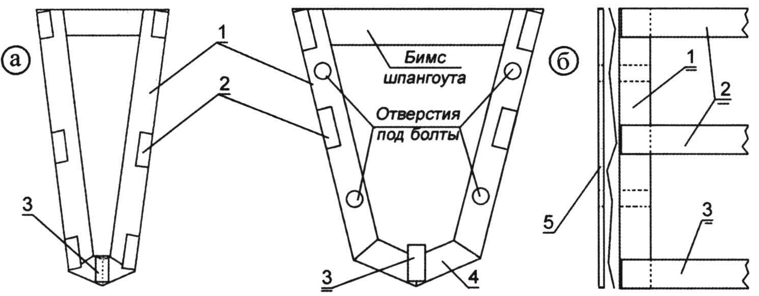
Series (a) and power (b) frames float:
1 – frames; 2 stringers; 3 – keel; 4 – braces-gusset plate; 5 – a lining
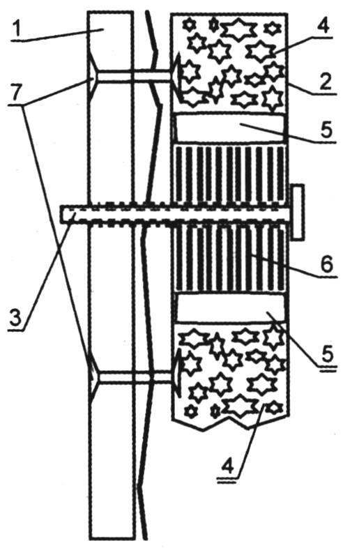
Mount bulkhead of the float stringer:
1 – frame; 2 – stringer; 3 – bolt; 4 – Styrofoam; 5 – a sealant; 6 – amplifier; 7 – exhaust rivet
The tension and the attachment of a covering:
1 – stapel; 2 – gasket; 3 – stud; 4 – frame; 5 – casing; 6 – gon (process detail); 7 – tension screw
Novice shipbuilders, even before you start designing, it is advisable to study existing similar vessels, paying attention to the positive aspects and disadvantages. If possible, ask the advice of experienced builders of sailing ships, to in its design to avoid repeating their mistakes.
Drawings of the catamaran was performed using the computer program AutoCAD. But many elements and even individual assemblies produced sketches. As practice shows, it is better to draw on roll paper every detail in scale 1:1, reducing the digs only the length of the longitudinal members.
To avoid errors in the construction of the catamaran, it would be nice to make a model in scale 1:5 made of cardboard and wood – it will allow us to understand the purpose of each object, to verify the accuracy of the drawings and to determine the order of Assembly. After impregnation, the layout may be launched for testing.
When the project of the catamaran was ready, my friends conducted a study on strength characteristics of basic elements of design that have shown their reliability.
DESIGN
Floats. From the outset it was assumed that catamaran is collapsible, to transport it on a trailer. In addition, to simplify the process of making floats, high vitality and buoyancy of the catamaran, each float designed composite of several, connected by bolts of compartments filled with foam.
The deck of the floats are flat and made of corrugated sheet AMG2 thickness of 2 mm. deck Items (for each compartment) through a rubber strip attached by self-tapping screws to the upper stringers.
The beams. The floats of the catamaran are connected by four cross beams – beams. Podmoscovye BIMS is equipped with a device opposing its deflection from the pressure of the mast when tensioning of cables.
The steering device is coupled consists of two feathers, the tillers from them connected by a transverse rod, the middle of which is attached to the extension arm.
The centerboard located between the floats, installed in working position (lowered into the water vertically) under its own weight. From the longitudinal and transverse displacements recorded by pairs of tie rods (cross – lanyards).
The mast consists of three tribes, the United ambulante. Put on podmoscovye BIMS through the heel and steps and raskreplenija the forestay and three pairs of guys. Standing rigging – stainless steel cable with a diameter of 5 mm. When using a special profile mast rigging can be simplified. But it is better to increase the strength of the rigging (resigned with increasing mass) than to break the mast at the wrong time.
Sailing rig – Bermudian sloop. A grotto with a large hammer is equipped with six through-armor. The jib is twisted on the forestay. Running rigging made of nylon rope used for fixing the Cam retainers.
Awnings-deck. For the accommodation of passengers and crew between drift boats and feed the BIMS is stretched an awning, and the cargo is placed on the awning between the front and podmazova the BIMS. Awnings are made of durable synthetic fabric, or of special awning mesh. The disadvantage of fabric is that in contact with the awning, the water not completely drain, but the spray from the floats do not fall for cargo and crew.
MANUFACTURING OF ELEMENTS OF THE CATAMARAN
If the construction of the catamaran is planned in the cold season, the room needs to be heated. The dimensions of the workshop, at least, should allow to assemble the float at full length. Of course, to install the mast in the operating position (vertically) on the catamaran in any room possible. But to collect it in full, without installation, just need. In addition, collected the mast may be lapping the grotto. Thus, the length of quarters shall be 8 metres and a width of not less than 3 m.
For Assembly of the power set of partitions of the floats of a catamaran and the subsequent plating metal came prepared with a sheet of chipboard size 1830x2440x25 mm cut two boards (covers) with a thickness of 40 mm, a length of 2200 and a minimum width of 100 mm. of these elements made the slipway. Drawings posted on the wall near the slipway. On the surface of the chipboard with markers of different colors caused the layout corresponding to the position of the frames and stringers floats. Boards (covers) are installed on the line of the stringers and fixed to chipboard screws. For fixing frames in a vertical plane from plywood, sheet metal and scraps “corner” made struts.
As a long ruler, you can use sections of the box (so on the factory price list is denoted by a tube made of alloy AD31 rectangular 40x20x2 mm), which are manufactured stringers.
The DSP (the stocks) are first complied with the drawings.
Special attention had to be paid to the process of assembling individual elements of a catamaran. It would be nice to record the order of installation of each part on its place. Here also will help layout. If, after the construction of the Assembly will remain in any detail, one must go back to is not repeated on the actual design. On the layout error is easy to fix, and a real design error will result, at best, additional costs of time, materials and money, and at worst – loss of strength, failure during operation, etc.
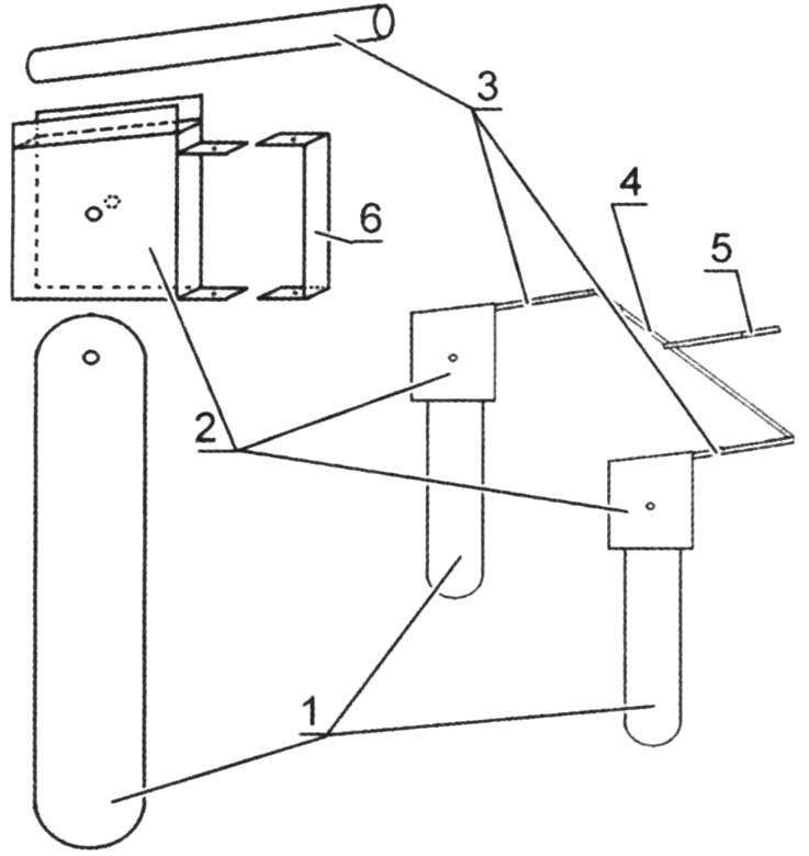
Steering gear:
1 – NIB; 2 – steering box; 3 – a fastening device; 4 – tiller; 5 – stopper of Carlina
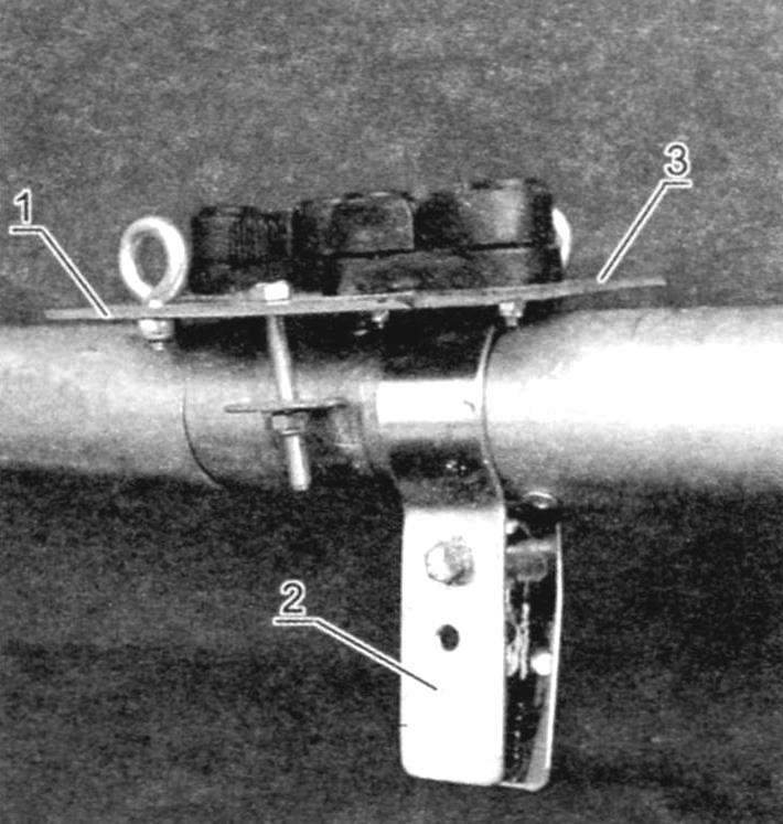
Hose clamp:
1 – the deck of the float; 2 – bolt clamp; 3 – a collar; 4 – a coupling bolt; 5 – BIMS
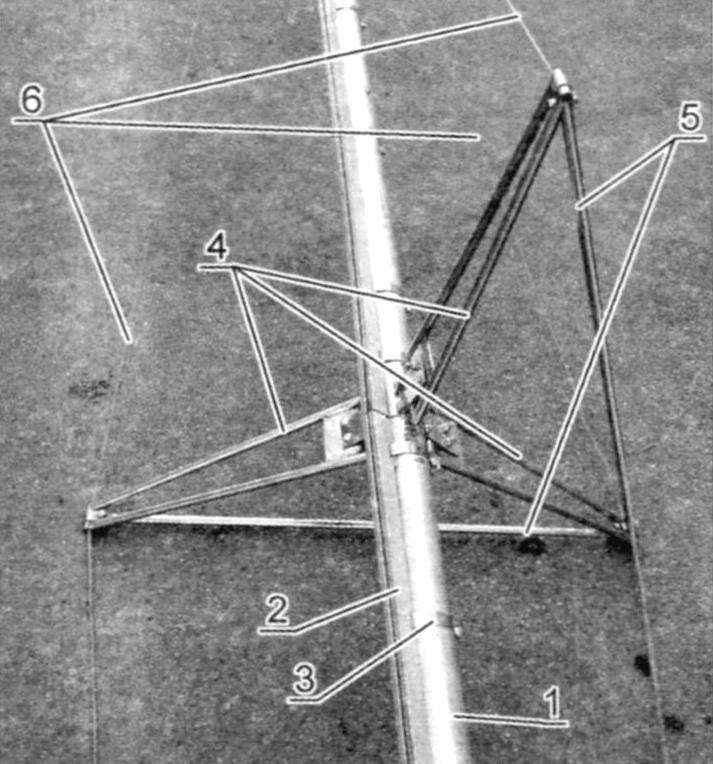
Podmoscovye node, steps (welded options) and the scheme of joining of the mast and beams:
1 – mast; 2 steps; 3 – clamp; 4 – podmoscovye BIMS; 5 – podmoscovye node; 6 – a cable with lanyard; 7 – bolt M10
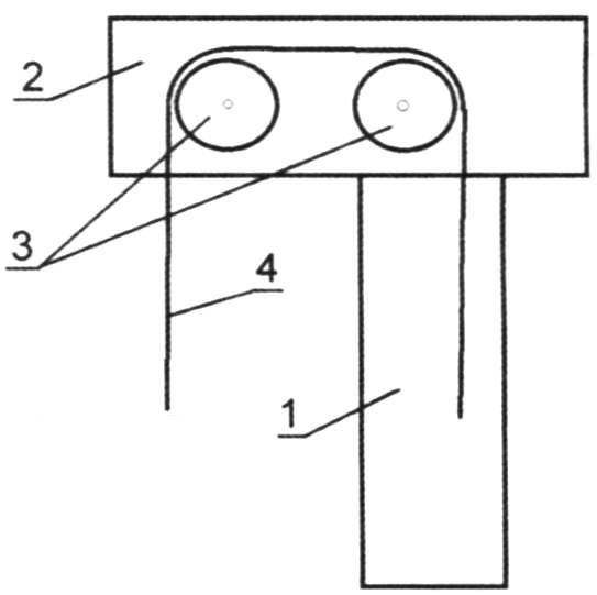
The Central part podrachivala beams (without welding):
1 – podmoscovye BIMS; 2 – thrust; 3 – steps (attaching the bottom of the mast); 4 – blocks running rigging; 5 – lanyard; 6 – cable; 7 – clamp-clip
In the manufacture of structural elements of the catamaran without welding, using the connection details only “exhaust” rivets, screws and bolts with nuts. Some elements are held together by pins. In addition, each section of floats laid the foam blocks to provide buoyancy.
Preferably the hollow parts made from Boxing (stringers, frames amplifiers), fill with foam and reinforce holes in them, which will be connected to other elements of appropriate size with metal plates.
Floats of a catamaran interchangeably. As already mentioned, the float consists of four compartments – nasal, intermediate, basic and feed. The division of the middle compartments of the float on the “intermediate” and “basic” is conventionally, for ease of story construction. Intermediate compartments of the float is fixed podmoscovye BIMS, fixed the shrouds and forestay, between them is stretched a cargo awning. On the main compartments, or rather the awning-deck between them is the crew.
Power set of each compartment of the float, (except for feed), made of two upper, two middle and two lower stringers, keel and frames. The feed element has only the upper and lower stringers. Stringers and keel – longitudinal strength elements are made of “Boxing” (the title comes from the factory price list) – rectangular tube section 40x20x2 mm from alloy AD31. The stringers are fixed with segments of the area to the frames. Stringers are fastened to the sheathing and elements of fixing of the rigging. Frames transverse force elements, serve to make the body shape. To the frames are plastic (it also carries a substantial burden), intrashell the beams and power components of the rigging. The frames are made from sheets АМГ2н 2,0x1200x2500 mm. Conventionally, the frames can be divided into “power” and “internal”. “Power” frames (No. 2, 5, 8) located at the junction of each element and serve for the mounting of the floats during Assembly of the entire float. “Power” frames amplify the segments of the box (alloy AD31 40x20x2 mm).
The “internal” frames (no 1,3,4, 6, 7,) located in the middle of the elements. For fastening sheathing “internal” frames are enhanced by squares (alloy AD31 30x30x2). Frame No. 9 is located in the aft end, it is attached to the steering device.
The procedure for manufacturing the “power” of the frame (Fig.7) the following;
1. Cut from a sheet (АМГ2н 2.0 x 1200×2500 mm) flat part of the frame, to mark and severity recesses (only recess, not a hole completely!) for the installation of exhaust rivets “flush”.
2. Cut out box (alloy AD31 40x20x2 mm) reinforcements and mark the holes for the connection elements of the floats.
3. To procure from scraps of sheet 1 mm thick reinforcements of the holes.
To install (for the markup) to the segments of the box elements enhance, fill both sides with silicone sealant (layer thickness 4-6 mm), to fill the space with foam from a cylinder.
Grease the bottom plane of the amplifier silicone sealant, let dry a few minutes.
To impose on the flat elements of the frame amplifier and fix it (e.g. hand grip).
Drill one hole (preferably with edges) for “pop rivets” and to connect the parts of the rivet, then drill a hole on the other side and secure the second rivet.
Remove the vise, to drill the remaining holes and fully pin element.
Similarly, install the remaining amplifiers and the frame is almost ready.
After making another frame for the neighboring element (for example, # 2 for bow and 2 for intermediate) needs to attach the frames to each other relevant stakeholders, to commit and drill the holes for the bolts which will connect the elements.
To facilitate Assembly, can be mounted on one of the “power” of the frames (e.g., ø2 nasal element, Ш5 main element, sh8 feed element) of the nut (Fig.8). This will simplify the process crackdown, using only one key.
For the production of “internal” frame (Fig.9) need:
1. Cut from a sheet (АМГ2н 2.0 x 1200×2500 mm) flat part of the frame, to mark and severity recesses (only recess, not a hole completely!!!) to install the “exhaust studs” “flush”.
2. To make a square from reinforcements.
3. To consistently pin the squares to the flat element, drill holes and fix the angle brackets “rivet”. The frame is ready.
The stringers are also made of the “box” (an alloy AD31, 40x20x2). For fixing the frames to the stringers harvests of the area (AD31 alloy 30x30x2 mm) lengths of 40 mm to all elements of the catamaran (approximately 80 PCs). Angle brackets to mount bendable to an angle slightly more than the drawing. Thus the stress state of the connecting elements ensure the reliability of the design. Easier to attach the sections of the corners to the frames before Assembly of the power set.
The frame is mounted for Assembly to the nose element.
Mounted on bench frames and fix them to the vertical struts. Mounted on the panel stringers and fix them with screws. Thus the rear ends of the stringers flush fix in place, and the bow end of the stringers should not be connected. Drill a hole in the stringer and also fix the joint with a rivet. Do the same thing on the other side. Fix rivet the stringers to the bulkhead No. 1. Bring the nasal ends of the stringers in place and fix them with a strip of metal and rivets. Sequentially starting from the frame № 2, fix the middle stringers, the nasal tip is also connected. Fasten to frames and keel. Rivets connecting the stringers and keel with amplifier (band alloy AMG 1,0x100x500 mm).
The most difficult is the layout of the sheathing (sheets of dimensions 1,0×1200*3000 mm or 1 mm 0x1500x3000 alloys AMG2, AMGZ or AMG5). If you order a layout, after Assembly of the power set it is necessary to wrap a sheet of drawing paper and mark the boundaries of the cut. If the sheet is put on the table, You will see that the boundary is a polygon. Similarly, we can proceed on the original. Four sheets of drawing paper glue tape. Edge gluing the fingerboard to fix the pile tape, or buttons. The envelope of leaves around the elements of the power set as tightly as possible. Apply the line of contact “plating” and the power set. Get a drawing that is transferred to the metal sheet. It should be borne in mind that to bend metal like paper, home conditions very difficult. Therefore, the fold line is applied to the inner surface of the covering and on the edges you can leave the stock in a few mm Cut from a sheet of a workpiece for plating and bending it. Fix the workpiece to one of the top 3-4 stringers by rivets. To the opposite edge of the sheathing to temporarily fasten multiple parts so that the lower plane was 5 – 7 mm above the edge of the hull. Raise the opposite stringer 10 – 15 mm above the plate. Pull the trim pad of the bench with screws through the corners. Fix the lining to the upper stringers by rivets 30 -35 mm, and average 100 – 120 mm. Fix the cladding to the vertical members of the frame amplifier No. 2 30 – 35 mm, and the lower elements 50 and 55 mm. the Most complicated is fixing the bow plating. There are several options. It is possible to make the outer covering from amplifier stainless steel band with a thickness of 1 mm and fix it with 4-5 bolts and nuts. And head bolts, and the nut must have a spherical surface. However, aluminium and steel make up the galvanic couple and the sheathing will eventually fail. You can make outdoor amplifier strip 500×100*1 mm alloy AMG and fix it with rivets. Excess skin on the edges are removed with a angle grinder or a file.
The nasal element is almost ready, it remains only to seal the joints to make the deck and fill the compartment with foam.
For sealing joints used are of different compositions. At the first Assembly silicone sealant dissolved nitroresorcinol (acetone, solvent 646), the mixture was treated all joints of individual parts, each “exhaust stud” a bolted connection. Processing operation for possible leaks exterior water were repeated up to 4 times. This allowed for 2 seasons about leaks to forget. However, in the third year of sealing it was decided to repeat. Used bitumen sealant that is diluted with gasoline “Galosha” (B-70), the resulting composition also handled all the problem areas. For a complete elimination of leaks separate places (for example, joints of the “power” frames) covers non-woven material that is applied on the sealed surface and the top again put the sealant.
The gaff rig on the mast:
1 – mast; 2 – likes; 3 – fasteners likasa; 4 – stand crispity; 5 – strut crispity; 6 – ambulante
The top of the mast:
1 – mast; 2 – bracket; 3 – block; 4 – mainsail halyard; 5-likes; 6 – bracket likasa to the mast
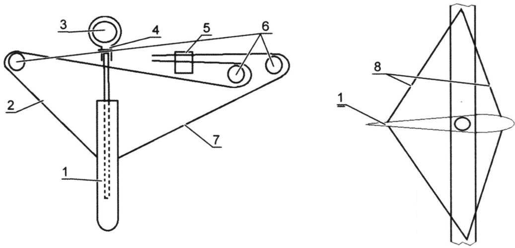
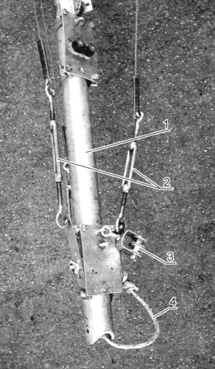
The centerboard:
1 – the centerboard; 2 – rope lifting centerboard; 3 – podmoscovye BIMS; 4 – clamp; 5 – stopper; 6 blocks; 7 – the rope installation of the centerboard in its working position; 8 – the ropes, the restraint from lateral movement
Chertovy BIMS
1 – svetovy BIMS; 2 – mounting bracket centerboard; 3 – area of attachment of the retainers fixing the centerboard in the operating or raised position
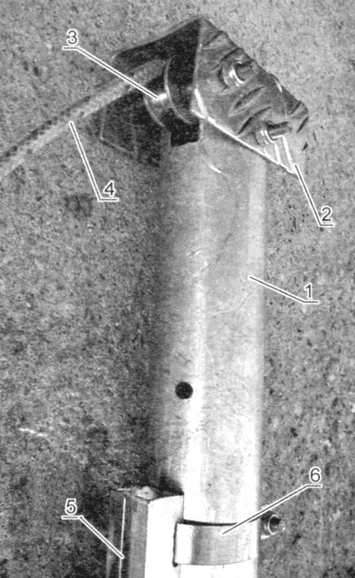
Spurs of the mast (lower mast):
1 – mast; 2 – lanyard ambulant; 3 – block lines boom; 4 – grateful
Steering gear:
1 – rudder, 2 – the stock (steering box); 3 – tiller; 4 – connecting rod; 5 – the extension tiller; 6 – bracket on the frame No. 9
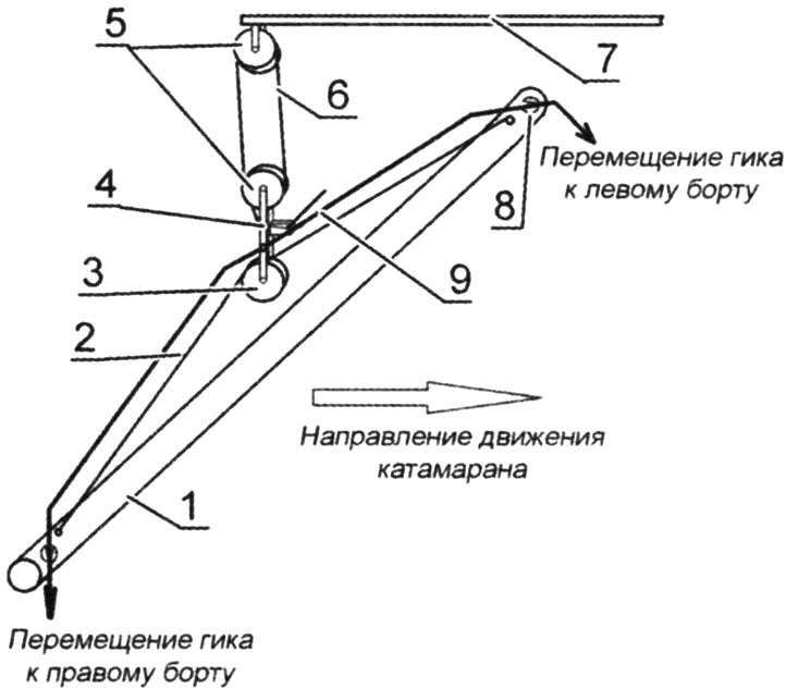
Epaulet ghica-sheet:
1 – aft beams; 2 – rope shoulder strap; 3 – block overhead; 4 – a stopper of boom mainsheet; 5 – sets of boom-mainsheet; 6 – gigasat; 7 – boom; 8 – stopper; 9 – rope of the ring of gigaslot
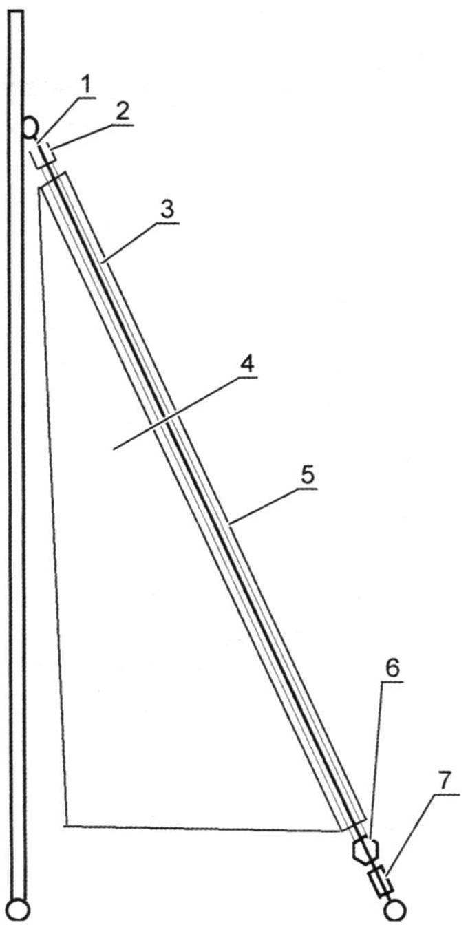
Mount the sail on the forestay:
1 – forestay; 2 – upper bearing; 3 – cowling; 4 – staysail; 5 – pocket headsail; 6 – coil twist; 7 – lanyard
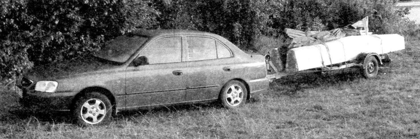
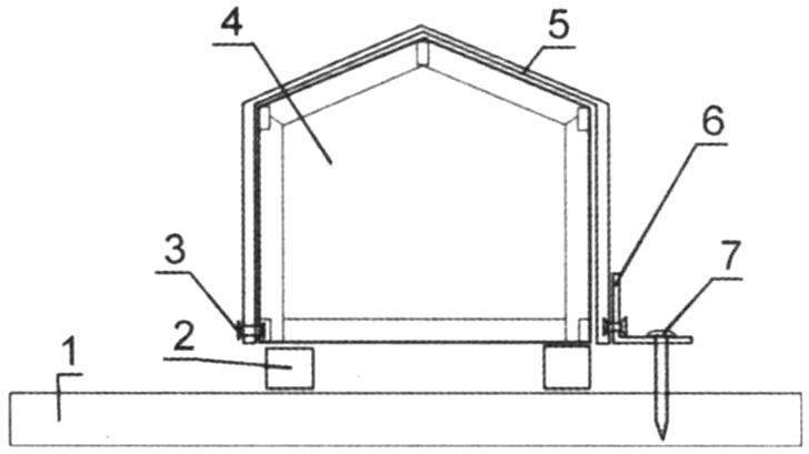
Transportation of the catamaran on the trailer car
Each compartment of the float is filled with foam (you can use any soft foam sheet with a thickness of 50 – 100 mm). Leave empty compartments for storage of cargo is impractical for him enough space in the front awning. During a hike at the Gorky reservoir in 2009, the remaining cavity is exposed to water, the floats sank into the water completely, but not drowning, helped foam. It must be remembered that nitrobacteria corrode the foam.
Manufacture of other elements of the float is similar to the bow, the difference in the size of components does not matter.
Bimson for fastening, uniting the floats into a single structure, are used the clamps made from strips of stainless steel of thickness 1.5-2 mm and a width of 25 – 30 mm. the Clamps are fastened to the stringers with bolts and nuts. It is advisable to strengthen the attachment of the clamp plate of stainless steel. This will distribute the load on a larger surface. To fix the BIMS is used in the clamp bolt M8 self-locking nut.
Fore and aft beams – chimney (AD31 alloy) with a diameter of 60×2 mm. For mounting the mast on podmazova the BIMS is made of the steel steps. To neutralize the load on the beams is podmoscovye node, which by means of a cable 8 mm thick (minimum) and lanyard creates a force opposite to the pressure of the mast. Steps and podmoscovye node are fixed on the beams by two clamps. On podmazova the BIMS sets the block through which the rope to control the centerboard.
On svetovom the BIMS is installed the centerboard, cables cross fixing, stopper ropes that control the position of the centerboard.
In the initial option for making masts used pipe 40×1,5 mm from alloy AD31. However, the strength of the design was insufficient. Subsequently, for the manufacture of the mast was used pipe 50×2,5 mm. the Mast consists of three sections. Lower and middle – long 3 m, the top is 1,5 m.
Lik-groove made of “Boxing” 15x 15×1,5 (alloy AD1). One wall with a hammer bend inward so that the face-groove good contact with the mast. On the opposite side was performed kerf width of 2.5 – 4 mm. cutting Edges are carefully sanded, so not to damage the front leech of the sail. Lik-groove mounted on the mast clamps with screw tightening. The distance between the clamps 200 mm in the lower part to 400 mm in the upper part of the mast. The top of the mast, equipped with blocks for the transaction files. The halyard of the mainsail is passed inside the mast. After setting the mainsail the lower end of the tether lays a duck at the bottom of the mast.
The forestay is fixed at 3/4 mast height. Over the upper attachment point of the forestay you can solidify a block for a Spinnaker or gennaker.
The gaff rig made from pipes with a diameter of 12×1 mm, material – stainless steel. The gaff rig is installed at the junction of the lower and middle knee of the mast. Is fixed on the mast clamp.
The greatest difficulty, in my opinion, causes the production of sails. I sewed them myself, seven times for measuring and then cutting and sewing every detail on its place. Briefly and clearly describe this process quite difficult. And the details is better to study the literature. In addition, for the calculation of the sails are computer programs. Who have the opportunity, sail making it is better to order in special workshops.
Guys and ambulanti made of stainless steel wire rope with a thickness of 5 mm. due To the fact that the mast made of pipe 50×2,5 mm, on a catamaran have three pair of guys. The top is attached at the junction of the upper and middle of the knee of the mast (about 4/5 of the steps). The other two pairs, the average increase (above krispity) and lower (below krispity) of the mast. Front guys appeared on streamline design. Their purpose is to reduce such fluctuations of the floats, when the nose of one of the float rises, and the nose of another is lowered.
The ends of the cables of the rigging is fixed by the binding posts from copper pipe 8×1 mm. For protection of the wire strands from chafing, it is desirable to make shackles. For the final adjustment of the length of the cables used lanyards with thread M8.
Venturini are made from strips of stainless steel of thickness 1.5 – 2 mm width 20 – 25 mm. to Strengthen Venturini appropriate to the upper longitudinal stringers in the area svetovogo of BIMS. To hook the lanyard from falling out of the holes of venturanza, after the cable tension necessary to wrap the hook tape, duct tape or band-aid.
The centerboard profiled, made of steel sheet of 1 mm thickness (alloy AMG). Its power element – stainless steel tube 15 mm in diameter. Rear cut riveted “rivet” sizes 3,2×8 mm, of which the core is removed. Pipe pre-installed in the middle part of the centerboard and after the connection of the rear slice is fixed to the casing of the “rivet”. At the top of the pipe drilled hole for installation of the centerboard in a turning bracket fixed to the beams. It means the leading and trailing edges of the centerboard rope attached, by which it is installed in operating position or removed from the water to the stern. For fixing the centerboard in the diametrical plane of the catamaran are the cables, the length of which is adjustable lanyards. Good the centerboard can be made of wood, and even better to utformat of fiberglass with epoxy. But it’s more complicated than to manufacture it, as the rudder blades, sheet metal.
The steering device is coupled, consists of balaraw (steering boxes) with a rudder, tillers,connecting rods and arms. Steering boxes are made of sheet metal (you can use scraps from pieces for the deck) and scraps of angles 30x30x2. Connect the elements using nuts and bolts or rivets. The rudder is made similarly to a centerboard, tube aluminum alloy, the internal cavity can be filled with foam. In the upper part of the rudder has a hole to attach the pen in the steering box. For fixing the rudder in the operating and raised position sorlini fixed tiller fixed to the Cam retainers. The tubular tiller attached to the steering box bolts. Coupling rod (pipe, alloy AD31 30×2,5) is attached to the tillers with bolts and nuts. The tiller extension is fastened to the middle part of the connecting rod with a special clamp. The extremity of the extension for ease of use wrapped fabric roll plaster (in any case not plastic duct tape). Can be done at the end of the extender handle. Extension cable (or a pen) it is advisable to perform rotating around its axis.
For fixing steering boxes on the aft bulkhead (Ш9) is attached to the bracket from a strip of stainless steel 2 mm thick and 20 mm wide. Boxes are fixed with a long hairpin.
For feeding the BIMS system is equipped with wiring and stoppers geek of the sheet. Stoppers headsail Scots and other elements of the running rigging is located in the area svetovogo of BIMS.
For the manufacture of the sail to twist the workpiece with the forestay has a top fire, put on the upper bearing, the tube-fairing. On the luff of the headsail is equipped with pocket to put the staysail on the fairing. Then put the bottom coil-twist. In this case, the pocket to equip a 1-2 gap in those places where there are loose joints in the elements of the fairing. For subsequent fixation of the joints of the fairing is necessary to provide sections of pipe of smaller diameter mounted on the cable stays. Then equip the lower fire. Instead of the tubular gripping, infinitely adjustable and you can secure the rope in multiple screw stoppers. Before installing the headsail all the elements of the fixed fairing, the fairing is fixed to the upper bearing and the coil twist. You can then fix the upper part of the forestay to the mast. Pocket headsail manually sheathed so that the sail is sitting firmly on the cone.
Of course, mistakes in the construction of the catamaran has happened, to correct them, at times, it was difficult, but the vessel has been built and successfully operated for many years.
ASSEMBLY AND TESTING
And then came the moment when all the components of the vessel are ready. But do not rush to the water. First Assembly recommend to hold on the land, in a place where there is access to electricity; not fit some sort of hole, it is necessary to cut off the excess metal, but you never know what to do. And when there’s a power drill, jig saw, electric saw, it is easier to eliminate defects.
The Assembly of the catamaran begins with the connection elements of the floats. It is advisable to loosen the fasteners in joints of compartments to put sealant on the bolts, let dry 15-20 minutes and retighten the bolts. If the test leakage is not found, you can leave the Assembly until the end of the season.
On podmoscovye BIMS is installed and fastened steps, podmoscovye node, and svartby – stoppers shvertovyh ropes and svetovoy bracket. In this “curb” as these beams can be permanent.
Be sure to raise the sails, check the free there is a grotto in the face of-the groove, good work blocks and stoppers. Check the operation of the overhead of wakasato, stoppers mainsail is the mainsheet. Several times expandable / collapsible jib. Check the correct wiring of the Scots, the work stops. Check the position of the mast: the deviation from the vertical in the transverse plane is not allowed. Tilt the mast back can be no more than 6°. Pull the backstay of the mast. With the power shaking the mast, check whether you hold the stoppers and a tubular binding posts guys and the forestay. Install the centerboard, check adjustment of cables, wiring ropes. Collect the steering device. Tensioned awnings passenger and cargo decks.
After checking and adjusting all elements of the parse catamaran for transport to the water.
Preparation of the catamaran for the trip is held in the horizontal section a few metres from the water. It is desirable that the process involved three people, this will facilitate and speed up Assembly.
My trailer allows you to carry front compartment Assembly with the intermediate and aft with the main. So from beginning to end, collect the floats, not forgetting the sealing of joints. Then one of the floats (for example, to the left) fasten the fore and aft beams. The right float is placed under the right ends bimson, align and tighten the bolts. Set chertovy and podmoscovye the beams. Collect sections of the mast and pull ambulanti. Recorded the lower end of the mast (spurs) from the nose, set it in steps, and measure the stud or bolt with nut. Spreading along the sides of the shrouds, fastened to the mast the forestay. For lifting the mast it is advisable to use the winch, such as that which is available on trailers for transportation of boats. In addition, you need to pull the middle a couple of guys at podmazova beam. This will prevent the mast from the side zavalivanija. Using winches and measures for the protection zavalivanija allow you to install the mast alone. It is necessary to exclude the presence of outsiders in the area of the lifting mast. After you install the mast vertically fix the shrouds and forestay to avoid the falling mast. Check and adjust the position of the mast.
Install the centerboard and steering device. Attached to the bow and stern beams the tents and pulled them with ropes. We launch a catamaran into the water and to depths of up to 1 m allow to stand for 15-20 minutes, check the tightness oscow floats through the open deck. If no leaks, decks battened down. Svetovoe cranks and steering device.
Near the water’s edge set sail: mainsail, staysail.
ATTENTION! The water should be JUST in the rescue vest. Hands must be wearing gloves. Check whether we have forgotten the oar, let it lie on the forward canopy is fixed rubber strap.
I’m not an ascetic, but I will state categorically: water and alcohol don’t mix. When we are with friends in 1990 gathered the first catamaran, was born a tradition that is observed at the beginning of each season.
Catamaran hull (and nothing else) sprinkled with cognac.
Select the first output when on the water, no boats and people, the breeze, the waves there. Let next to You will be the boat with friends, ready to help… and give help is needed! Please be patient. There will be more wind and waves, the whistling of rigging, and the spray in the face…
V. TEREKHOV
Recommend to read
 OUT, BUT NOT IMMEDIATELY
One of the inconveniences in the design of many cars is that the interior light goes out immediately when closing the doors. There are, however, a special device to delay the power light... WAY IN THE SKY
A circle of aircraft modeling at the station of young technicians of the Novocherkassk Polytechnic Institute, the air force, where he became a Navigator of a military aircraft, was the...
