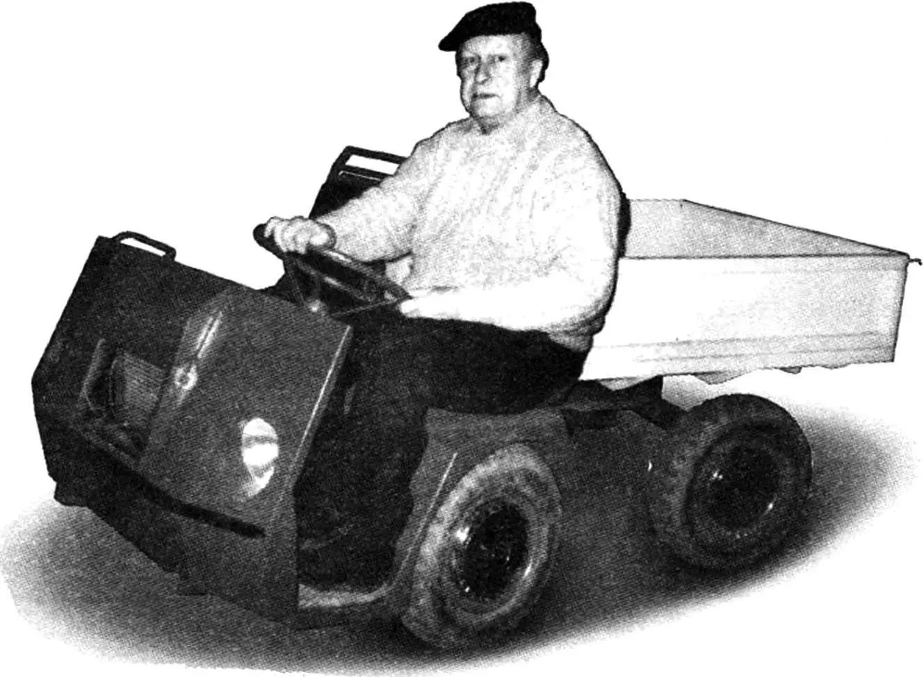
The designer of this small truck — Yevgeny Nikitovich Yevsikov is already known to our readers from the publication «Plows, carries and even saws» (see «Modelist-Konstruktor» No. 5, 2002). The article was about a small tractor he built. Now we present another of his machines — a mini-truck.
Yevgeny Nikitovich is a leading designer with 40 years of experience at the famous Mil helicopter plant. The truck he designed and built — worthy of rotary-wing machines — is reliable and practical. Moreover, it shows that simplicity and neatness which are ensured by thoughtfulness and quality execution of each unit. The first photo of the mini-truck was published in «Modelist-Konstruktor» No. 6, 2002 under the heading «Photo panorama from readers’ letters».
What passenger and cargo cars have not been created by domestic designers: from luxurious «parade-exit» limousines to «ascetic» sports buggies, from multi-ton heavy haulers to swift «Gazelles».
However, machines for household use, so to speak, service vehicles — small and simple, reliable and inexpensive — are somehow not to be seen. Designers adapt «Izh», «Moskvich», «Zhiguli» for these purposes, converting them into pickups. But the price of the machines remains the same as passenger cars — not everyone can afford it, and not everyone will dare to carry sand, bricks, soil and other similar cargoes in bulk on them. And they are not adapted for driving on country roads at low speeds. In this situation, perhaps only the cargo scooter «Muravey» can help, but it also has its drawbacks: air cooling of the engine, low power, steering wheel location in the middle of the track, open chain drive.
Industry cannot or does not want to organize production of such a machine for household use, apparently considering this niche unpromising. But from my own experience I know that such a truck would be useful not only to summer residents, but also to rural residents who have a farmstead.
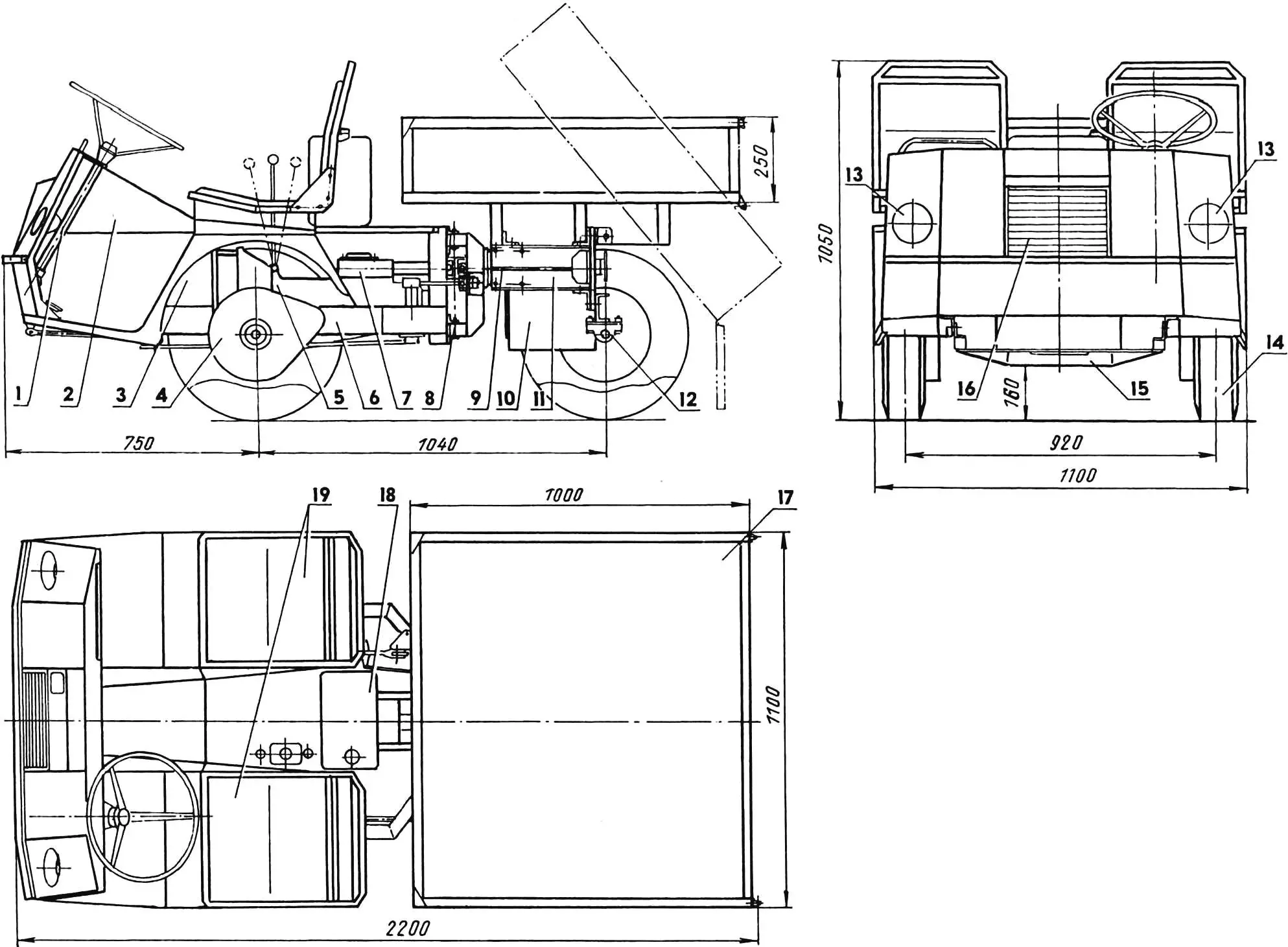
1 — steering column; 2 — engine hood; 3 — engine; 4 — wheel reducer; 5 — clutch basket and gearbox; 6 — front subframe; 7 — power take-off shaft engagement/disengagement mechanism; 8 — vertical axis of the frame articulation joint; 9 — horizontal axis of the frame articulation joint; 10 — battery box; 11 — rear subframe; 12 — rear axle beam; 13 — headlights; 14 — wheel; 15 — front subframe cross beam; 16 — radiator grille; 17 — body; 18 — fuel tank; 19 — driver and passenger seats
The prototype of the truck and even its «donor» was a mini-tractor that I made even before the start of building the country house. Let me remind you, since there was no electricity on the site, this tractor was used by me not only (and not so much) for land cultivation or as a cargo cart tractor, but as a drive for various construction units: mortar-concrete mixer, woodworking machine, etc. For this, the mini-tractor had a power take-off shaft. I considered it necessary to install the same shaft on the truck. The new machine inherited from the mini-tractor (the need for which had disappeared by that time, as electricity was still supplied to the site) wheel reducers, wheels (from SZD motorized wheelchair), gearbox (from ZAZ-965 car) and a «breaking» frame with some modifications. It is precisely this design that provided the truck with high maneuverability — it can turn around almost in place.
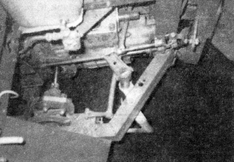
The front subframe underwent the greatest modernization: it became longer, wider, its cross member was now made composite, and the rays diverged at an angle of 36° to the side members — so as not to interfere with the increased (up to 20° in each direction) «break» of the frame. Instead of engine brackets, I installed an engine platform made of 6-mm steel sheet on it, and between the axes I mounted a curved beam from channel No. 8, which significantly increased the rigidity of the structure. I extended the side members with extensions, each of which I made from a pair of steel angle segments No. 4, riveting them with flanges along the length, thus obtaining a Z-shaped profile. Only its post with lugs remained untouched in the front subframe.
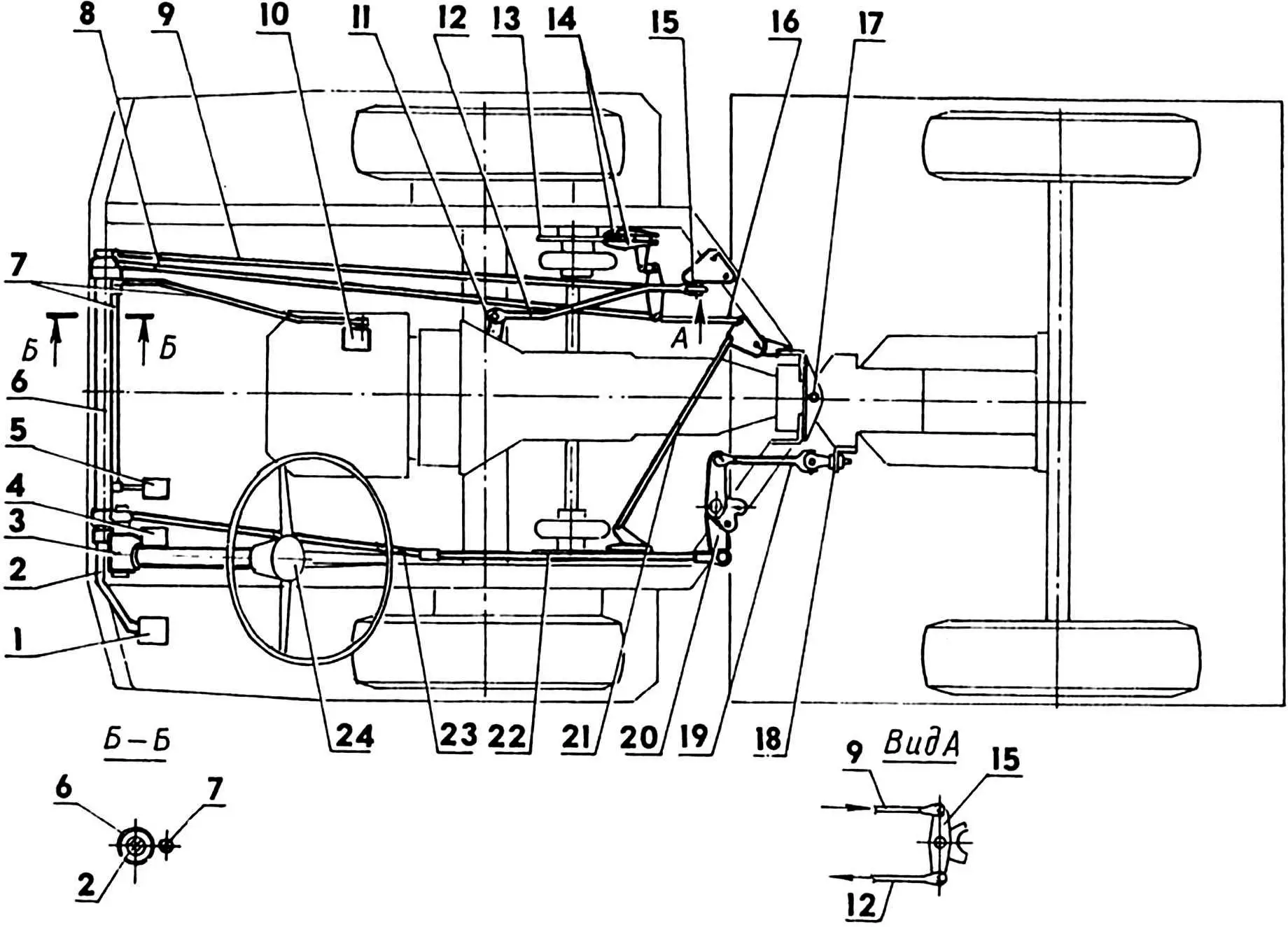
1 — clutch pedal; 2 — drive shaft; 3 — steering mechanism; 4 — brake pedal; 5 — carburetor throttle valve control pedal («gas»); 6 — brake drive shaft; 7 — carburetor throttle valve control drive shaft and rod; 8 — side brake drive rod; 9 — side clutch drive rod; 10 — carburetor; 11 — clutch lever; 12 — reverse clutch drive rod; 13 — brake disc (2 pcs.); 14 — brake pads; 15 — clutch drive rocker; 16 — intermediate brake rod; 17 — vertical axis of frame «break»; 18 — rear subframe pivot bracket; 19 — articulated («break») steering rod; 20 — paired steering control rocker; 21 — cross brake rod; 22 — intermediate side steering control rod; 23 — front side steering control rod; 24 — steering wheel and steering column; all rods are made from Ø14 bar
The rear subframe remained practically the same. I only replaced the rear axle beam with a longer one to widen the track and moved it behind the transom plate to increase the truck’s wheelbase. Calculations showed that this beam can be made from a single channel No. 8 (on the mini-tractor it was made from two such channels, without calculation). At the same time, there was still a significant safety margin.
The machine’s dimensions were limited by the condition that it should fit together with the «Zhigulenok» in one standard garage measuring 6×3.2 m.
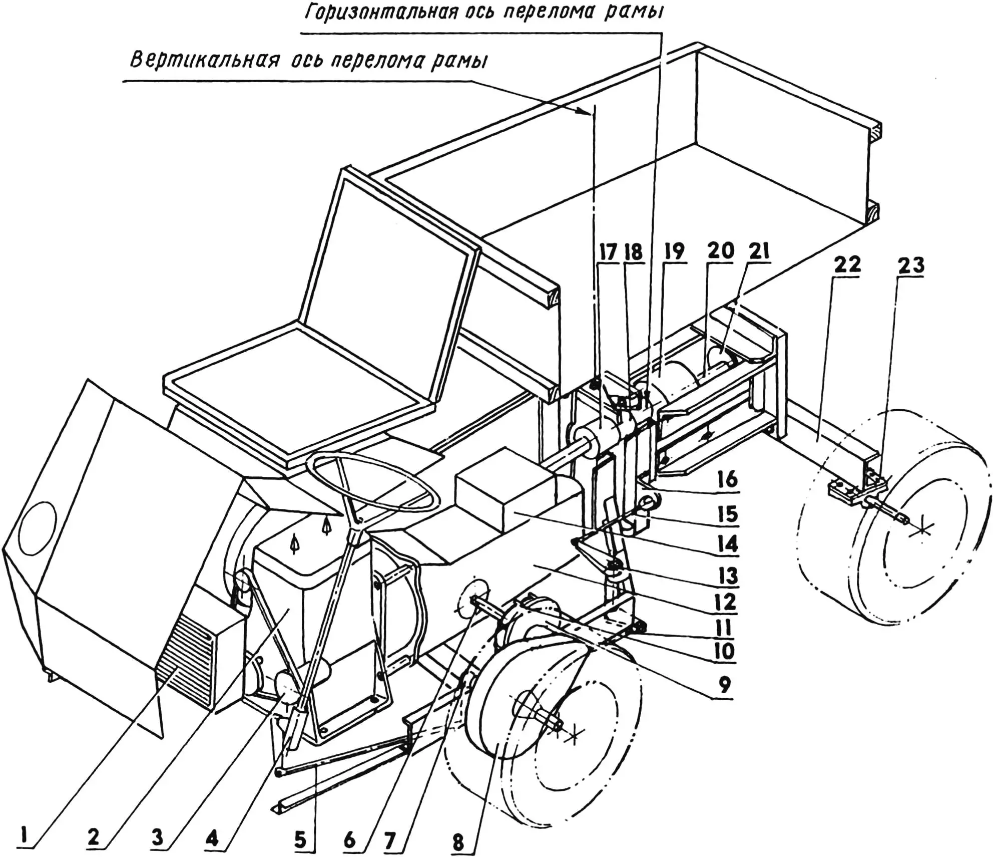
1 — radiator; 2 — «Hercules» engine; 3 — liquid pump; 4 — steering mechanism with pitman arm (from «Moskvich» car); 5 — front side steering control rod; 6 — half-shaft (2 pcs.); 7 — front (intermediate) steering control rocker; 8 — wheel reducer (2 pcs.); 9 — brake disc (2 pcs.); 10 — half-shaft rubber coupling (from «Zhiguli» car, 2 pcs.); 11 — intermediate side steering control rod; 12 — gearbox with clutch basket (from «Zaporozhets» car); 13 — paired steering control rocker; 14 — power take-off shaft engagement mechanism; 15 — articulated «break» steering rod; 16 — rear subframe pivot bracket; 17 — first universal joint of power take-off shaft; 18 — second universal joint of power take-off shaft; 19 — bearing unit with swivel bushing; 20 — third power take-off shaft joint; 21 — rear bearing support; 22 — rear axle beam; 23 — axial bracket
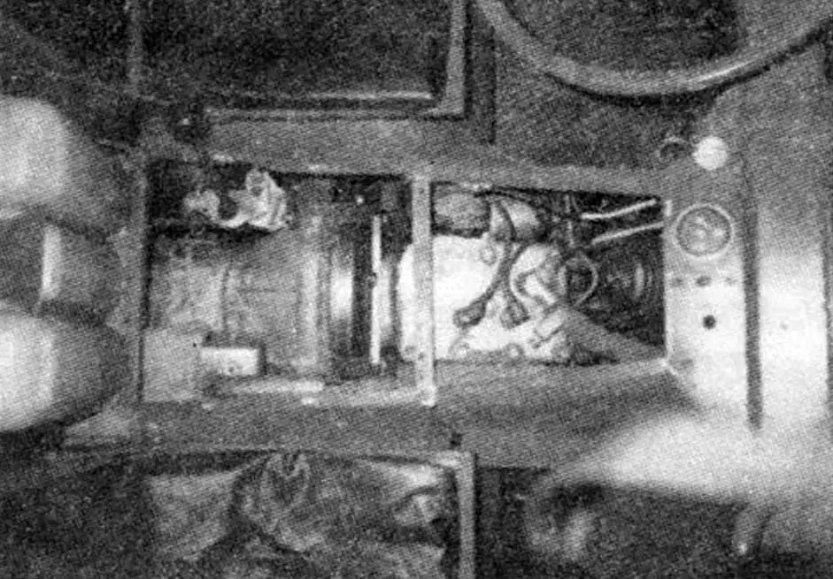
Although the dimensions and design of the front subframe are significantly changed, the layout of the power unit and transmission — engine with gearbox and power take-off shaft, half-shafts with wheel reducers — remained similar to that on the mini-tractor.
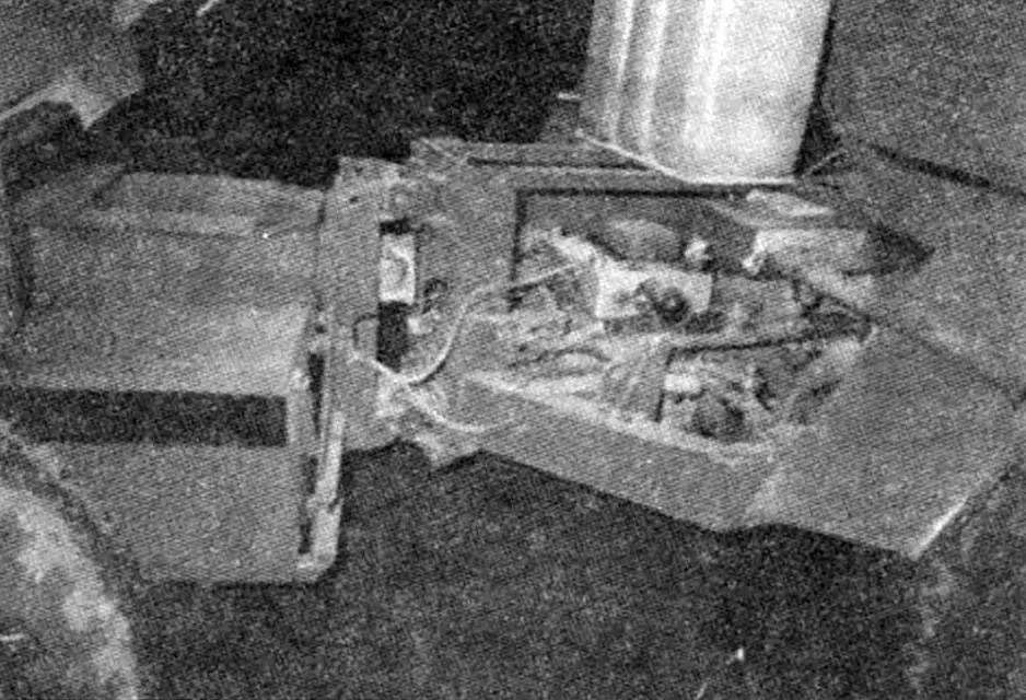
On the extensions of the side members I mounted an open cab with comfortable seats: for the driver — above the left wheel on the fender, and on the right fender — the passenger seat. On the outside, on the front panel of the cab in its middle I placed the radiator grille, and on the sides — headlights. On the rear subframe I installed a spacious wooden body, and under it — a battery box.
The truck’s engine with the loud name «Hercules» is of American manufacture, 2-cylinder, 4-stroke, with a cast iron block and liquid cooling. I acquired it by chance from a neighbor at the dacha, to whom it somehow got and lay for many years unused. The motor was not new, and moreover «frozen» — with a cracked cooling system jacket at the top. It attracted me with its compactness. The Ulyanovsk UD-2 that stood on the mini-tractor was almost twice as large in dimensions, and in power — only 8 hp.
I overhauled the «Hercules» — surprisingly, the parts had almost no wear and rust did not reach them. I sealed the crack on the jacket with sealant VGO-30-1. Good sealant, withstands temperatures up to 250 °C (although the coolant does not heat up to such a temperature), and now tested by time — the jacket’s tightness has not been compromised.
The engine cooling system includes a fan with shroud, centrifugal pump and radiator — compact, but with almost doubled (compared to a conventional one of the same size) heat dissipation. The fan and pump are driven from the engine crankshaft by a V-belt drive. To monitor the coolant temperature, a sensor is installed on the cylinder block, and an indicator on the instrument panel.
But a fuel level sensor and indicator were not even needed. The fuel tank — a translucent polyethylene canister — is located in plain sight, between the backs of the driver and passenger seats. Fuel (gasoline of the lowest quality) flows by gravity to the carburetor through a shut-off valve with filter. Next to the liquid temperature sensor on the instrument panel — the ignition switch. The engine is started by a starter.
The ignition system is from a magneto. The headlights with high and low beam and the starter are powered by the battery. Light control — by a toggle switch on the instrument panel.
For the joint operation of the starter from the «Zaporozhets» car with the «Hercules» flywheel, I had to mount a gear ring from the Zaporozhye flywheel on the latter.
The truck’s chassis is of tractor type with rigid wheel suspension. All wheels are of the same size — from SZD motorized wheelchair. The driving and braking wheels are the front ones. Damping — by the pneumatic tires.
The transmission consists of a clutch basket with gearbox from the «Zaporozhets» car, half-shafts with elastic rubber couplings (front driveshaft from the «Zhiguli» car) and homemade wheel reducers. The reducers, in addition to a significant reduction in the number of revolutions (i = 6.35), reverse the rotation of the half-shafts, since the gearbox on the truck is rotated 180° relative to its position on the «Zaporozhets». The rubber couplings compensate for misalignments of the half-shafts with the wheel reducer shafts. Brake discs are rigidly mounted (welded) on the reducer input shafts.
For the power take-off shaft (PTO) drive, I removed the top cover from the gearbox and mounted the PTO engagement mechanism in its place. The shaft itself is a driveshaft transmission of several «knees» with joints. Its first «knee» is docked to the engagement mechanism shaft by means of a keyed connection. At the frame «break» location, the PTO has a double joint (from a pair of crosses). In the rear subframe it passes through two bearing units and between them has another «helicopter» joint. At the very end of the last «knee» behind the transom plate a flange is installed, to which the matching flange of the drive shaft of some unit or mechanism can be connected. The PTO rotation speed is regulated by the engine speed.
The truck control is classic: to the left of the steering column — clutch pedal, to the right — brake and «gas» pedals.
The steering column and steering mechanism with pitman arm — from the «Moskvich» car. The force to turn the rear subframe is transmitted by a system of rods, rockers and levers. The last rod at the frame «break» location has a cross.
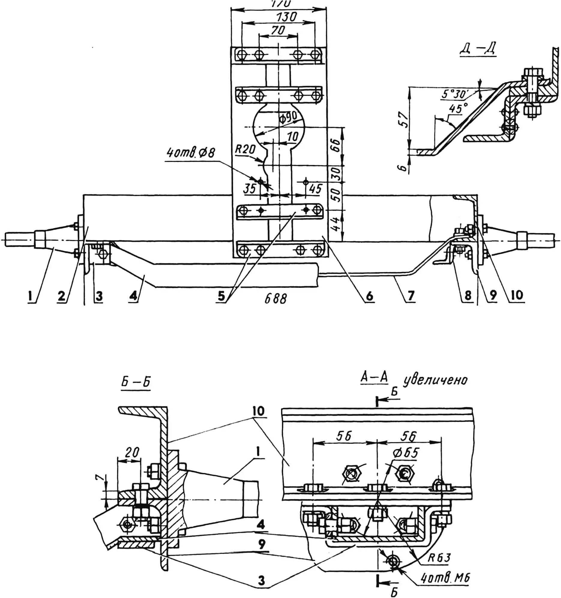
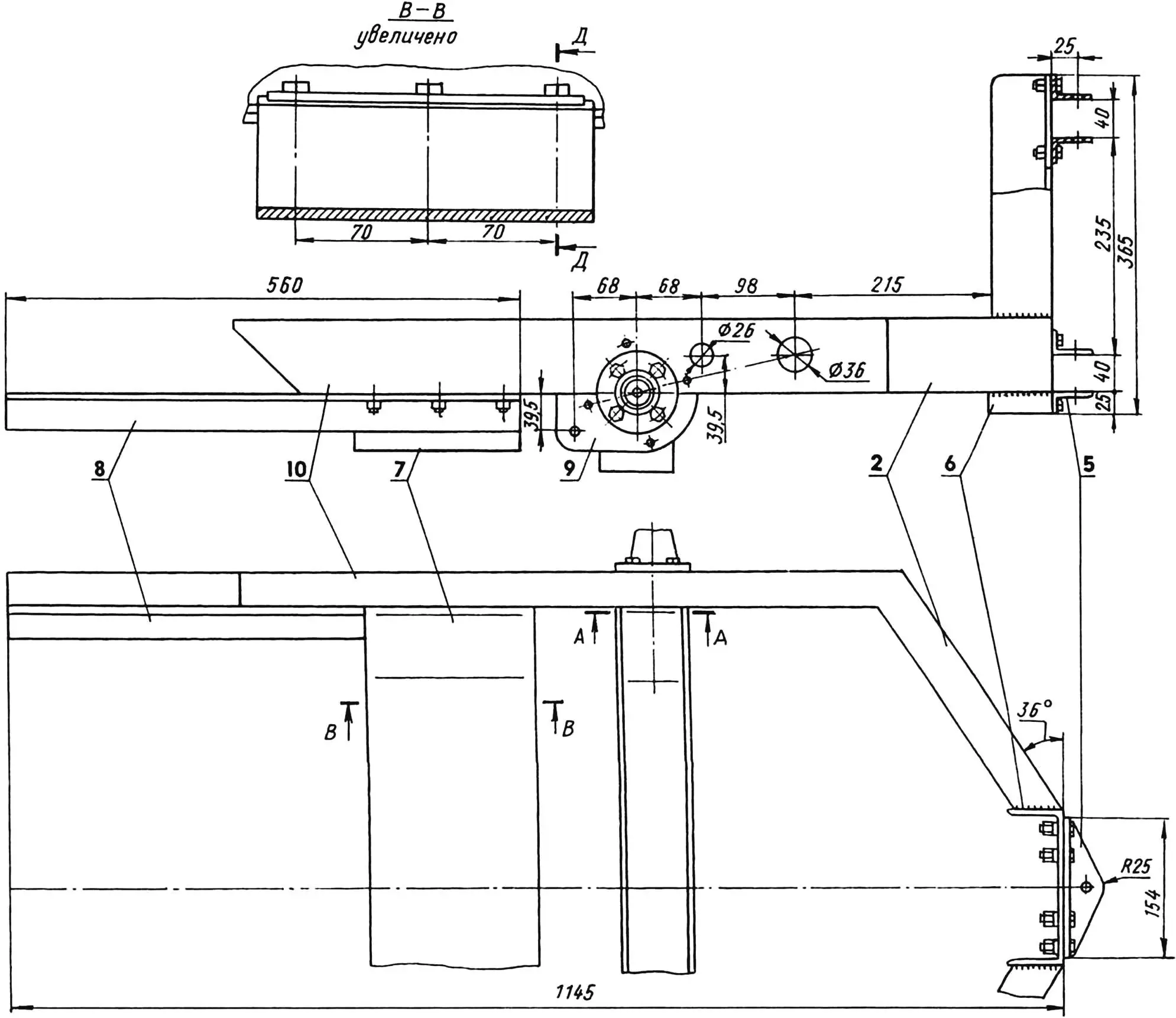
1 — front wheel hub (steel 45, Ø85, L138, 2 pcs.);2 — angular cross member (channel No. 8, L320, 2 pcs.); 3 — cross beam mounting bracket (steel, sheet s6, 2 pcs.); 4 — cross beam (channel No. 8); 5 — lug angles (angle No. 6.3, L154, 4 pcs.); 6 — post (angle No. 6.3, L365, 2 pcs.); 7 — engine platform (steel, sheet s6); 8 — extension (angle No. 4, L560, 4 pcs.); 9 — wheel reducer mounting sector (angle No. 6.3, 2 pcs.); 10 — side member (channel No. 8, 2 pcs.)
Since the truck control pedals are located on the left side, and the carburetor throttle valve, clutch and right brake pad control levers — on the right, shafts with levers are used to transfer forces from the pedals from side to side. Further, forces to the actuators are transmitted again using rods, levers and rockers. For compactness, the clutch rod shaft is laid in the tubular brake shaft in sliding bearings — nylon bushings inserted into the ends of the tube.
A wooden body is located on the rear subframe. Its frame is made of 35×35 mm bars, the sheathing is plywood. For self-dumping of cargoes, the body is mounted on the subframe with hinges — on an axis in two lugs, and the rear side is made hinged.
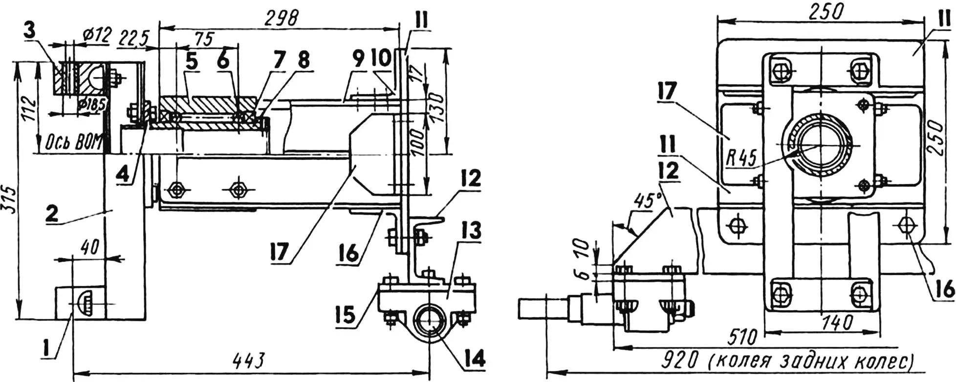
1 — lug; 2 — post; 3 — bushing; 4 — docking plate; 5 — swivel bearing unit housing; 6 — tie stud M12; 7 — bearing 1000915 (2 pcs.); 8 — swivel bushing; 9 — horizontal rib; 10 — upper cross member; 11 — rear transom plate; 12 — rear axle beam (steel, channel No. 8); 13 — axial bracket; 14 — rear wheel axle; 15 — transition plate (steel 20, s6, 2 pcs.); 16 — lower cross member (steel, angle No. 6.3); 17 — vertical rib (steel, angle No. 6.3, 2 pcs.);
parts 1—11, 13,14,17 — from mini-tractor (see «Modelist-Konstruktor» No. 5’2002)
The body is raised by shifting the cargo’s center of gravity backward. To prevent spontaneous lifting in the transport position, the body is additionally secured to the rear subframe with two M10 screws.
The truck’s maximum speed is slightly over 40 km/h. I consider this quite sufficient for such a vehicle. The engine power is enough to start a loaded machine even from 3rd gear, and an empty one — even from 4th. You need to get used to controlling the truck — turning using the frame «break» after driving a car is quite unusual.
And although after arranging the dacha plot the need for the truck, in general, has disappeared, I still keep it together with the «Zhigulenok» under one roof. I cannot bring myself to disassemble it for parts — it turned out to be a successful machine.
Main parameters of the mini-truck
Dimensions, mm:
length … 2200
width … 1100
height … 1050
Body dimensions, mm … 1000x1100x260
Wheelbase, mm … 1040
Track, mm … 920
Weight, kg … 350
Tractive effort, kg … 300
Load capacity (with driver and passenger), kg … 200
Power, hp … not less than 20
«Modelist-Konstruktor» No. 7’2002, E. YEVSIKOV
Recommend to read
 THE MEDALLION OF HEALTH
Flu epidemic rolled on us with ominous frequency. Someone trying to protect themselves from the disease influenza vaccination, someone takes medications and vitamins that improve the... TRUCK FOR THE FARM
It I designed for the needs of their country farms to remove construction debris from the site, and bring back to the ground. Therefore, the body — dump type with a hinged tailgate. The...
