The fuselage truss, tubular, collapsible design. The main element of the fuselage is a frame consisting of horizontal and vertical (pole) pipes ø 75X1, made of steel 30KHGSA. They are mounted towing hitch with lock and receiver air pressure, the dashboard, the pilot seat, secured with seat belt, control unit, tricycle, with a nose steerable wheel chassis mounted on motorhome power unit with a pusher propeller, stabilizer, keel with rudder ball joint to the rotor. Under the keel mounted auxiliary tail wheel with a diameter of 75 mm. together with the Pylon struts d 38X2 length 1260 mm, tubular beams, the main wheels d 42X 2 with a length of 770 mm, made of titanium alloy VT-2, and braces d 25X1 length 730 mm of steel 30KHGSA forms of spatial power frame, the center of which is the pilot. With the horizontal tube of the fuselage and the ball joint of the main rotor pylon connects with titanium rails. In the installation of the scarves in the tubes is established the bougies made of aluminum В95Т1.
Power unit with a pusher propeller. It consists of a two-cylinder boxer two-stroke engine working volume of 700 cm’1 with reduction gear, pusher propeller and electric starter, clutch system pre-spin the rotor, the fuel tank capacity of 8 litres and an electronic ignition system. The power unit is located behind the pylon on the engine frame.
The engine is equipped with a duplicate electronic contactless ignition system and tuned exhaust system.
Pushing the wood screw is driven through a V-belt gear, consisting of master and slave pulleys and 6 belts. The variability of the torque to the gear dampers installed.
The rotor diameter of 6.60 m — bladed. The blades are composed of fiberglass spar, foam padding and covered with fiberglass, is mounted on the sleeve with a horizontal hinge placed on the pylon. The ends of the blades located unmanaged trimmers to adjust sockanosset of the rotor. The propeller hub is made of duralumin brand В95Т1. The axis of the main rotor with a diameter of 25 mm, steel 30ХН2МВФА connected with a horizontal hinge, rotates in tapered roller bearings. On the axis of the rotor is installed, the driven gear of the gear pre-promotion and tachometer sensor rotor. The axis of the rotor is placed on a ball joint, which is connected with the top control plug. The last panel is installed with the pinion gear of the gear system prior to the promotion, hosted on the overrunning clutch, and a device of forced separation of the reduction gearbox of pre-promotion of the rotor. The drive gear is made via a cardan-spline shafts, angular gear, mounted on the pylon, and a friction clutch located on the engine. The friction clutch consists of a driven rubber roller mounted on the axis of the propeller-shaft is splined, and the leading dural drum, located on the axis of the engine. Management of a friction clutch carried by a lever mounted on the control handle.
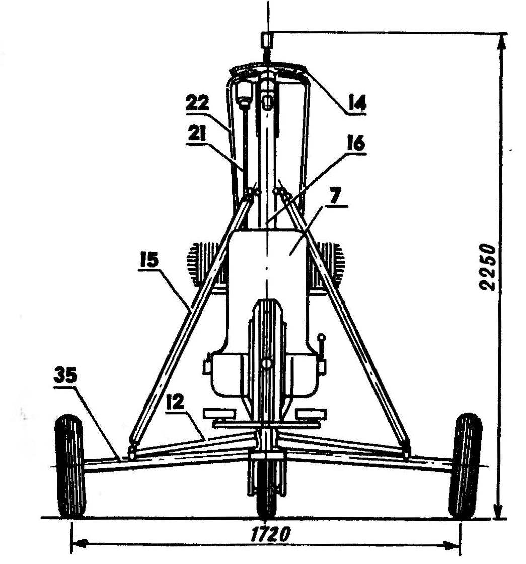
The layout of the autogyro DAS-2:
1 – Pitot, 2 — tow lock, 3 — dashboard, 4 — control knob 5 — control lever friction clutch system pre-spin the rotor, 6 — brake lever, 7 — seat pilot, 8 — control lever throttle carburetor, 9 — control lever device of the forced separation of the reduction gearbox promotion, 10 — foot controls, 11 — horizontal tube of the fuselage.^ — brace, 13 — lower plug control system, 14 — driven gear reducer promotion, 15 struts, 16 — pylon 17 — axis horizontal hinge, 18 — axis of the rotor, 19 — pinion gear promotion, 20 — the case of the overrunning clutch device and the forced separation of the gear unit promotion, 21 — pull control system, 22 — propeller-shaft slideway promotion, 23 — carb, 24 — bearing housing clutch promotion, 25 — push the screw 26, the sleeve pusher propeller, 27 — starter, 28 — gear pusher propeller, the gas tank 29, a 30 — main wheel, chassis, 31 — Kiel, 32 — brace the keel, 33 — rudder 34 — auxiliary tail wheel, 35 is a tubular beam of the main landing gear wheels, 36 — stabilizer-screen, 37 — console brace, 38 rocking rudder control.
In the front view of the rotor conventionally not shown.
Changes in roll and pitch knob are affecting the bottom plug the control rods associated with the upper fork, which in turn leads to a change of the inclination of the plane of rotation of the rotor. Plugs are connected with the rods of the model compounds using guided bearings. Directional control is the rudder connected cable runs with pedals, which controlled the nose wheel. To compensate for the hinge moment the rudder is provided with a compensator horn type. The rudder and keel symmetrical profile bead 16 made from plywood ribs with a thickness of 3 mm, pine stringers 5X 5 mm, covered with percale and coated with nitrocellulose lacquer. A keel mounted on the horizontal tube of the fuselage by means of anchor bolts and two cable braces. The relative thickness of the keel and rudder 5%. Stabilizer area of 0.25 m2 made of plywood with thickness of 3 mm, covered with percale and painted. The stabilizer has a zero angle and also acts as a screen pusher propeller.
A seamstress gyroplane — tricycle. Front driven wheel size 0 300X 80 is connected with the pedals by using a gear reducer with gear ratio 1:0,6, and is equipped with a Parking brake drum with a diameter of 115 mm. Main wheels — 0 450Х100. Wheel track — 1.72 m, base of 1.23 m. the main Tubular beams wheels mounted on a horizontal tube of the fuselage by means of rubber silent blocks, shock absorbers, chassis no. In the winter version landing gear wheels are replaced with skis or ice skates size 1,55X0,2 p.m. In hydrobalance chassis design permits installation of float whose length is 3.5 m, width 1.6 m, displacement — 500 kgs.
The instrument panel is located on the farm towing device. On the instrument panel mounted speed indicator, variometer, altimeter connected to the Pitot, tachometer rotor and pusher screws. On the control handle are toggle switch an emergency stop of the motor and the control handle friction clutch. Levers throttle control of the carburettor and the device forced separation of the reduction gearbox of pre-promotion installed at the pilot seat on the left. On the right there is the ignition switch. To the left of the dashboard is the brake lever of the Parking brake. All drive mechanisms of the autogyro is by cables with budenovskiy shells.
V. DANILOV. M. ANISIMOV, V. SMARSHKO, Tula
Recommend to read WITH POLYGON — IN THE MUSEUM Heavy duty anti-tank gun BOB-25. The famous "sorokopyatki" — 45 mm 19K anti-tank gun of the sample in 1932 and its upgraded version 53K model 1937 was in fact the only anti-tank guns by... MILL THAT PLOWS Every year, while digging the soil with my family on the backyard plot where a tractor simply had no room to turn around, I thought:
"I need a motoblock-cultivator." Of course, I could,...