The design of the vehicle — frame. The cabin is located between the front and rear axles, and the body directly above the rear axle.
Frame — welded, spatial. The dimensions of its elements in the drawing this approximate as they have already removed with the finished design.
The base of the frame are two longitudinal pipes of an external diameter of 38 mm, connected among themselves in several places cross-beams of rectangular tube 40×25 mm.
All-terrain vehicle on the tires:
1 — the tire of the front wheel (the camera from the rear wheels of the combine “Niva”, 2); 2 — hood (plywood, s4); 3 — wheel (motorcycle Voskhod); 4 — petrol tank (motorcycle Voskhod); 5 — seat; 6 — passenger; 7 — step; 8 — wing (2); 9 — roof of the cab (leather); 10 — brake thrust; 11 — body; 12 — suspension arm (2 PCs.); 13 — cross strap (belt 32); 14 — the longitudinal belt (belt 4 PCs); 15 — brace suspension (2 PCs); 16—tie-rod (2 PCs.); 17—engine (from a motorcycle “Voskhod”); 18—starting lever with a rope; 19—steering knuckle; 20 — front wheel (2 PCs); 21 — beam (tractor); 22 — rear view mirror (2 PCs); 23 — driving wheel (2 PCs.); 24—the bearing shaft (2 PCs); 25 — shaft; 26 — drive sprocket shaft; 27 — a brake device; 28—rear fender (2 PCs); 29 — the tyre of the drive wheel (camera from the back wheels of the harvester KSK-100, 2 PCs.)
In the front part of the frame is welded a fragment of the engine subframe from a motorcycle “Voskhod” — for mounting on this engine, and to him — bezel headlights. Top edging additionally bonded screed with the steering column, which is the b-pillar frame of the front panel. Another screed itself connects the column with the seat frame, installed on the fuel tank, as the spinal tube of the frame of the motorcycle. To column welded two bushing steering shaft: one downstairs and another at the top.
To the rear ends of the side members are welded T-shaped lift pads of the bearing shaft of the rear axle. Sami area is made of two angle corners with dimensions 45×45 mm.
The body shell is also executed at the same time frame. But a great weight training it does not bear, and therefore made of square pipe 25×25 mm.
Back to the frame and to the body frame welded mounting brackets for fixing to them of the wings. But the elements of the skeleton of the cabin is made of wooden bars and aluminum tubes to parts of the frame were attached with M6 bolts.
For the windshield made my frame from wooden bruskov section 30x30mm. The frame rests on the upper cross member frame front panel of a rack which, in turn, is welded to the front ends of the side members.
Frame and body frame
1 — longitudinal (pipe d38, 2); 2 — strut (pipe 20×30, 2); 3 — mistichna spacer (tube d25); 4 — engine subframe (from the frame of the motorcycle “Voskhod”); 5 — trim headlamp (area 20×20); 6 — tie edging and steering column brace (pipe d25); 7 —steering column (tube d25); 8 — bushing the steering shaft (pipe d32,2); 9 — front bezel (tube d25); 10—coupling steering column and seat frame (tube d25); 11 — seat frame (tube 25×25); 12 — front podgotovkoy brace (tube 25×25,3 pieces); 13 — cross member (tube 20×40,3). 14 reference area of the housing mounting bearing shaft rear axle (paired area 45×45, 2); 15 — Podmoskovnye stand (pipe d25,4 pieces); 16 — rear podgotovkoy brace (pipe d25, 2); 17 — frame body (tube 25×25); 18 — polurama the rear wall (tube 25×25); 19 console rear wing (area 25×25, 6 pieces) 20 — through-the arc of the rear fender (tube d25, 2); 21 console front fender (tube d25,2); 22 — tripping (pipe d25)
Other elements of the skeleton of the cabin is made mostly of duralumin tubes from old clamshell. The cab and fenders and mikusova bulkhead is made of 4 mm plywood. Plywood panels attached to elements of the core bolts M6. The roof is covered with leatherette. Doors have no booth, and the floor as the seat is made of bakelizirovannoj of plywood 10 mm thick. On a plywood base last put the foam and it is upholstered in leatherette. Passenger seat — folding, is in the back. Of the bulkhead as the cabin, trimmed with 4mm plywood and on the floor also put a sheet of 10-ply bakelizirovannoj plywood. Tailgate to body opening made in the door hinges.
Transmission (transmission of torque from the engine to the propeller) consists of two chain transmissions with intermediate shaft total gear ratio i = 3,1. Sprocket mounted on the output shaft of the power unit, has 15 teeth. For its production was used by hub staff and its crown — combine. From it the rotation is transmitted to 18-bevel sprocket on the intermediate shaft. At the other end of the installed 28-bevel star — from her chain goes over the drive shaft of the rear wheels, on which is fixed a large sprocket driven by number of teeth — 72. All gear wheels, and chain have the same pitch 15,875 mm and used from combine harvester “Niva”. The tension of the front chain — similar to a motorcycle, and rear — with idler sprocket. The front circuit has a fairly long, but she slips on the hardwood (oak) rails, which serve the function of the stator.
Scheme of transmission, braking system and steering of the Rover:
1 — engine; 2 — output shaft sprocket (driven), z = 15; 3 — drive chain, the first stage t = 15,875; 4 — an intermediate shaft; 5 — counter shaft sprocket z = 18 of the first stage chain drive (small asterisk of an intermediate shaft); 6 — tensioner circuit of the first stage; 7 — sprocket z=28 the second stage chain drive (large asterisk intermediate shaft); 8 — tensioning sprocket chain second stage; 9 — drive circuit of the second stage t = 15,875; 10 — the driven sprocket z = 72 the second stage chain transmission (drive sprocket drive shaft); And — the drive shaft; 12 — the drive wheels on the dog low pressure; 13 — brake pedal; 14 — thrust; 15 — brake band; 16 — brake drum; 17 — steering; 18 — steering shaft; 19 — fry; 20 — tie rod (2 PCs); 21 — steering knuckle (2); 22 — the driven wheel on the low-pressure tire (2 PCs.)
Presenter (rear) shaft with a diameter of 30 mm and a length of 925 mm rotates in two bearings, which along with the buildings used are all from the same harvester “Niva” — they planted walkers. The bearing housings are fixed to the platforms of the frame — the rear ends of the side members.
Rear axle differential — because the all-terrain vehicle to ride on hard ground is almost not necessary — that’s not why it was built. And because the rear drive shaft is solid (and not from the axles, as usual in differential drive). At its ends is threaded M20, and at the extremes machined cone. Closer to the right (in the direction) end welded flange of a steel strip with scarves — attached to it a large led 72-bevel sprocket of the second stage chain transmission.
Rear axle:
a — axle Assembly (without wheels); b — rolling clemena scheme
Here mounted on the shaft is the brake drum (idler pulley from the combine), connected through a slotted flange, welded
Steering Rover — mixed (motor-car) type. Steering wheel with gas lever and clutch lever — motorcycle (“Sunrise”), and the guide wheel or two, like a car.
On the lower end of the steering shaft fixed plate (a Pitman arm) welded to it with bushings (the ends of the rotary levers of the car “Zaporozhets”) finger rods. Traction is made of pipes with a diameter of 20 mm and nibs, too, from “zaporozhtsa”.
Steering knuckles and the control arms of the front suspension is hand made. First on the hanger mounted shock absorbers from a heavy motorcycle, but they were weak. Then replaced them with rigid tubular struts with silent-blocks and tapped a finger on the top end. Vvorachivaya or twisting the pin out of the strut to adjust camber, eliminating the inaccuracy of the Assembly. The front wheel hub used on the cultivator for inter-row cultivation of plants.
The front (driven) wheel (all the mounting holes in detail under the M6 bolts:
1 — rim (from a moped “Riga”); 2 — eyelet disc (steel sheet s1,5,16); 3 — ring (double steel rod d8, 2); 4 — spokes (wire d6, 16 items); 5 — Central disk (plywood s 10); 6 — lodgements (steel sheet s2, 16 items); 7 — lateral disk (plywood, sheet s2,2 PC.)
The nodes of the front suspension:
1 — the lever; 2 — strut; 3 — a bolt; 4 — a rotary fist
The device forced air cooling of the engine:
1 — cylinder head of the engine; 2 — cruciform bracket; 3 — impeller (aluminum-headed sheet s2); 4, the driven pulley of the impeller (PCB); 5 — a casing (sides from cans of paint); 6 — timing belt-pasik (sealing rubber ring from the tractor starter); 7 — drive pulley (aluminum); 8 – special M8 stud extension shaft-generator rotor
Wheels — homemade. Design and size of the front wheels differ from the rear. As tires used for two cameras.
Finishing the description of the design of the Rover, I will say that the engine during operation of the machine has changed. After two seasons I replaced regular motor sprocket together with a chain and clutch on a matching of the motorcycle “Minsk”. The result is increased traction on the drive wheels.
And again. In slow traffic the engine overheated even in the cool weather. Had to provide it device forced air cooling. The main part of the device — four-bladed impeller with a diameter of 140 mm, is made of 2 mm aluminum sheet. To the impeller the three bolts attached to textolite M4 driven roller-pulley diameter 60 mm belt transmission sitting on the bearing.
They are taken from some airplane servo. The impeller is provided with a casing, which is used as the shell with a diameter of 150 mm cans of paint. And the impeller, and sides by means of a slotted bracket attached to the extreme edge of the cooling of the cylinder head. The impeller drive is provided from shaft-generator rotor, which is extended with special M6 pin, one end facing outwards. To this end, the shaft end performed deaf axial hole M6, and the lid of the generator, a hole with a diameter of 10 mm. drive pulley tight fit on the thicker neck of the stud is fixed against rotation by the key from wire with a diameter of 1.5 mm and secondrun nut M6 spring washer. The corresponding hole for the dowel drilled in place after the installation of the roller on the shaft. As Pasika (timing belt) used a rubber o-ring from tractor starting the engine D-240.
During the operation since 2001 Rover his appointment justified. Margin of safety it is also sufficient — there was no damage. Power the power unit suffices in order to carry pakuba oak firewood for second and even third gear.
N. KURBATOV, p. Borisovka-2, Belgorod region.
Recommend to read PAPER, BUT NOT QUITE These beautiful and flying planes is very simple. They can do and the guys who have not yet engaged in aircraft modeling. To work they need a dense drawing paper (drawing paper), a few... FLOWER HILL Indoor plants, even if they are not in bloom, pleasing to the eye is a part of nature. But for the growers is always a problem where to place them in the house? The most common...
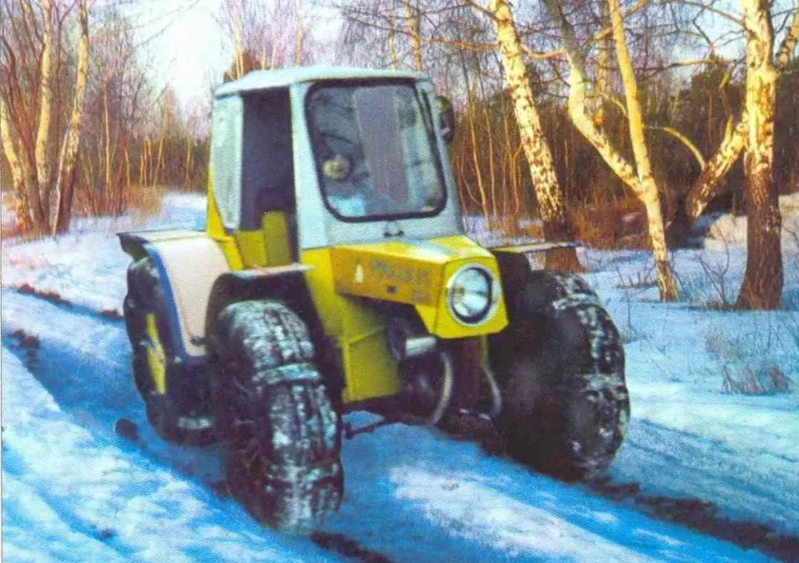
 The machine was conceived as a utility vehicle on which to carry at least small loads for the household in terms of “winter” and the winter terrain.