
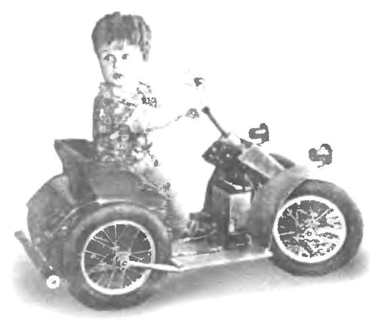
 When my grandson Grisha began to grow and stopped paying attention to previously favorite toys-rattles, the home began to notice that he started to show interest in different instruments and even mechanisms. Then I decided to make him a little electromobility-Quad, where in good weather you can ride on the street, and bad — Yves room. And not only that the child received pleasure from riding — mastering the driving skills he was introduced to technology, getting acquainted with its device.
The design is based electromobility is a platform made of an extruded one piece of furniture chipboard thickness of 16 mm. In front of the platform attached to two longitudinal members of channel cross section, curved steel strip with a thickness of 2 mm. On the longitudinal members mounted beam front axle, steering and front bumper. At the rear of the platform includes a drive consisting of two electric motors, reduction gearbox, intermediate shaft and chain drives with sprockets.
Wheel electromobility with pneumatic flotation tyres size 56-205. Two wheels taken from the old children’s bike “Bear”, and two (front and rear) purchased in the store, where was sold as spare parts for this bike. Since the suspension of all wheels tough, the depreciation is provided by the selection of optimal tyre pressure.
Drive wheels — rear. Both with freewheel and sprockets. In design, there is one feature: one wheel (right) provides forward movement and the other (left) back. To do this, both wheels are mounted with stars inside. The clutches work in opposite directions. Axis applied to the factory, from the bike. But to reduce the landing shoulder on them wheel bearings cone screwed on the thread maximum inside.
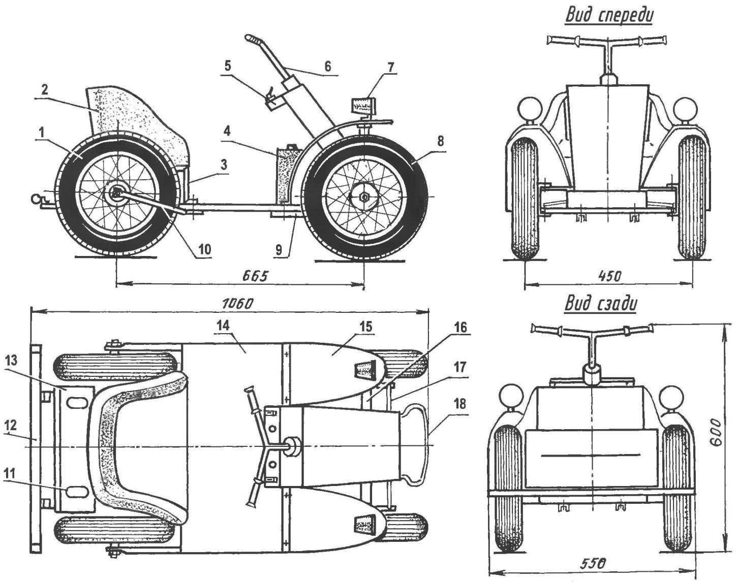
Electromobility-Quad:
1 — rear wheel (from a child’s Bicycle 2): 2 — seat (plywood, foam, artificial leather); 3 — supporting seat post (area 15×15, 2 pieces); 4 — battery (12 V, 9 A); 5 — bracket vehicles; 6 — wheel; 7 — dummy lamp with white reflector (2); 8 — front wheel (from a child’s Bicycle, 2 PCs.), 9 – spar (2 PCs.); 10 — longitudinal traction of the rear wheel Truba 1/2″, 2); 11 — white reflector (2); 12 — rear bumper; 13 — rear cowl (aluminum, sheet s1); 14 — frame platform; 15 —front fender (aluminum, sheet s1,2); 16 — front beam; 17 — tie-rod; 18 — front bumper (steel, sheet s2)
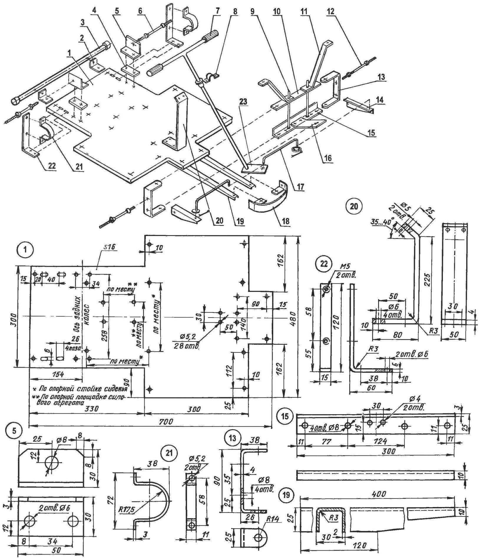
Frame area and suspension (standard fasteners: bolts, washers, cotter pin — not shown):
1 — frame ground (particle Board, s16); 2 — mounting brackets rear bumper (area 30×30,2 PCs.); 3 — rear bumper (pipe 3/4″); 4 — lining (DSP, s16, 2); 5 — axis bracket (area 30×30, 2 PCs.); 6 — axis of the rear wheel (from a child’s Bicycle, 2); 7 — the wheel (from a child’s Bicycle); 8 — bracket steering (steel, sheet l); 9 – M10 studs and nuts connecting the upper and lower traverse (2 PCs nuts 8 PCs); 10 — upper beam (steel strip 25×3); 11 — front fender bracket (steel strip 25×2,2); 12 — axle-axle knuckle front wheel (from a child’s Bicycle, 2); 13 – clamp steering knuckle (steel strip 25×4, 2); 14 – knuckle (area 30×30, 2 PCs.); 15 – lower front cross member beam (area 25×10); 16 — resistant bracket steering shaft (steel, sheet s3); 17 – tie rod (steel rod Ø5, 2); 18 – front bumper (steel, sheet s2) 19 — longitudinal (roll-formed channel 30×25 2 PCs), 20 — bracket steering shaft (steel, sheet s4); 21 — mounting bracket intermediate shaft bearing (steel strip 11×3, 2 PCs) 22 — bracket intermediate shaft (a steel, strip 15×6, 2); 23 — a Pitman arm (steel, sheet s3)
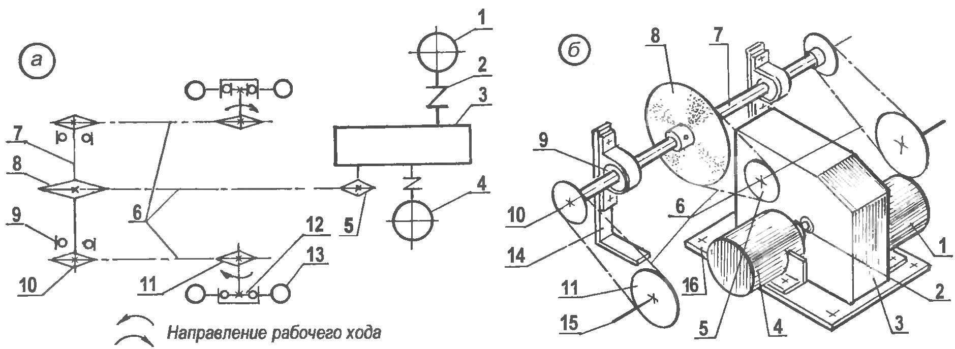
Kinematics (a) and General view of transmission (b) (parts and Assembly units positions 5,6,8,10,11,12,13 — old children’s bicycles):
1 — motor drive range (N = 20 W, 3000 rpm, car windshield wiper); 2 — coupling (rubber tube, 2); 3 — reducer (aircraft); 4 — motor reverse (N = 8 watts, 3000 rpm, from a car heater); 5 output shaft sprocket (z = 10); 6 — drive chains (t = 12,7); 7 — intermediate shaft; 8 — a large asterisk of an intermediate shaft (z = 30); 9 — the bearing 202 (2); 10 — small sprocket of the intermediate shaft (z = 8,2 PCs); 11 —sprocket sprocket wheel (z = 16,2 PCs); 12 — overrunning clutch drive wheel: 13 — driving wheel (2 PCs); 14 support bracket intermediate shaft; 15 — axis rear wheels (2 PCs); 16 – the supporting base of the power unit
The front wheels are driven. Wheel — type Bicycle. The steering shaft is mounted in two bearings (nylon bushings), its lower end is fixed a Pitman arm. She rods connected to the steering knuckle arms that hung on the bracket, pivotally connected to the ends of the front beam. And beam and fists were made without welding, thus a detachable Assembly unit consisting of several parts. The beam consists of upper and lower traverses interconnected by studs. The lower cross member bent from steel strip in the form of an area and its mid-mounted support bracket of the steering shaft To the upper traverse privernuty mounting brackets of wings, and she has the appearance of a simple plate section 22×4 mm.
The basis of a knuckle — clip. It is attached to pivot arm and axle-front wheel axis. Between the rubbing surfaces of the parts of the steering gear, where possible, put a nylon washer, the other swivel periodically lubricate with grease. In front of the spars are attached to the bumper. He figured. It also set the travel stops Pitman arm of the steering — wheel in each direction are rotated only by 45°.
Transmission could be a bit complicated and heavy. But sometimes purchased at a flea market cheap unusual, but any gear. As told about its origin, the seller — this mechanism from a scrapped aircraft. Advantages of this gear are few: it is lightweight (aluminum housing), compact, and most importantly — he had a very large gear ratio — 250. Even had the first two stages of the gear not to engage and dismantle. Two shaft of the subsequent gear while replaced by elongated and through the flexible coupling (wearing a very tight rubber tubing) attached to the motors.
Motors took car — both at 12 V with a turnover number of 3000 per minute. One of them is a power of 8 W (heater fan) is connected to the first shaft (after reconstruction) stage with a large gear ratio, the other — power of 20 W (wiper motor) to the shaft of the second stage a more powerful electric motor moves the car forward and the other backwards.
The motors initially attached to the corners, cut out the shelves in their vertical semi-circular grooves in the housing of the motors. Then, the reducer and the motors mounted on a common platform (DSP), and then the platform secured to the frame platform. This operation is made in place after mounting of the intermediate shaft and the axes of the wheels.
The power to the motors from the battery voltage of 12 V. the Battery is fixed to the platform beneath the steering column. Its charge lasts about 15 min of continuous driving. The battery has to be recharged about the same time with the charger operating on 220 V. the control over the restoration of the battery produced by the ammeter device.
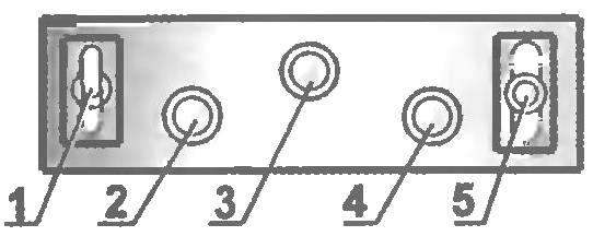
The dashboard, controls and alarms:
1 — two-position toggle switch and battery charging; 2 — the green light signalling the inclusion of forward progress; 3 — yellow light, stopping and neutral; 4 — red light alarm reverse; 5 — three-position switch (“Forward”, “Back”) and stop
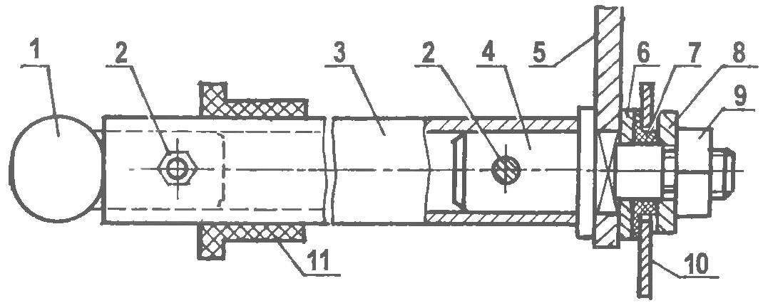
Steering gear:
1 — wheel; 2 — pin bolts M4; 3 — steering shaft (pipe 1/2″); 4 — shaft tip (St3); 5 fry; 6 — top washer (ft3); 7 – thrust bushing-bearing (nylon); 8 — the lower washer (ft3); 9 — nut M8; 10 — resistant bracket; 11 — upper shaft bushing (nylon)
Intermediate shaft:
1 — fastening of asterisks (screw M8, 2); 2 — spring washer (2pcs); 3 — washer (2 PCs); 4 — small sprocket (z = 8, 2); 5 — spring; 6 — the bearing 202 (2); 7 — shaft (steel 45, rod Ø17); 8 — bolt M4 spring washer (2 PCs.). 9 — big star (z = 30); 10 — bushing installation (St3); 11 pin-bolt M4 (the hole for the bolt is drilled after alignment of the planes of the sprocket of the OUTPUT shaft gear and a large sprocket of the intermediate shaft)
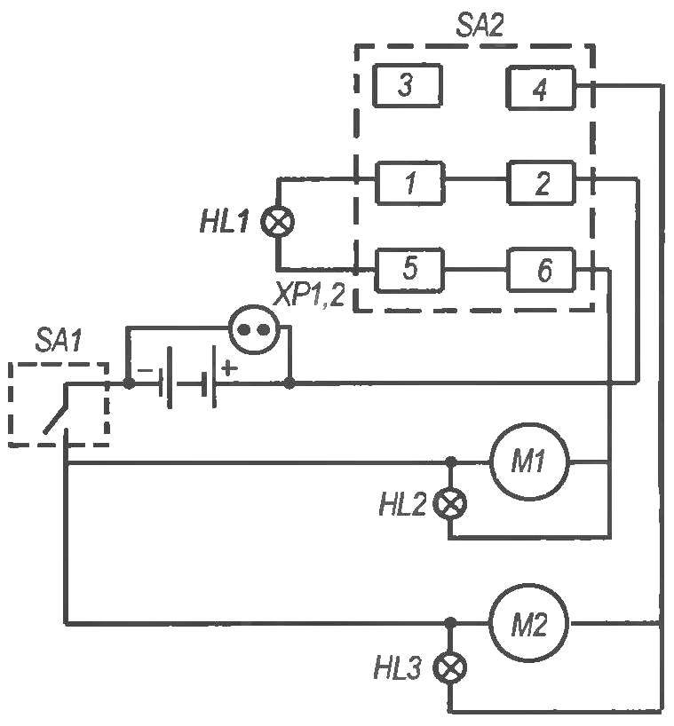
Wiring diagram:
M1 — motor drive (motor, wiper motor); M2 — motor reverse (motor, heater fan); SA1 is on / off switch t 1-2 enable power supply (ignition switch); SA2 — three position toggle switch П2Т-7 (27, 6 A) inclusion of forward progress (contacts 6-2), reverse (contacts 2-4), neutral (terminals 5-1); HL1 —yellow light alarm on the inclusion of neutrals; HL2 — green light alarm on the inclusion of forward progress; HL3 — red light signaling on the reverse; ХР1,2 — coupling half connector charger
When calculating the transmission speed of electromobility restricted to 5 km/h Because the user must that adults could easily keep up with him and control the actions of the baby. When the calculation took into account that the DC motors under load have great “slip” and instead of 3000 rpm will rotate only at a speed of 2000 Rev/min. But without a jackshaft with sprockets and chain drives still not done.
Sprocket on the output shaft of the gear has 10 teeth on the intermediate — large sprocket 30 teeth, and small — 8, and finally, the sprocket wheels — 16 teeth. The total gear ratio of the transmission is equal to 36. The pitch of the teeth of all sprockets and chains is the same — 12.7 mm. the Special mechanism of a tension of the circuits designed, and made, only instead of holes for the mounting bracket the intermediate shaft at the site of longitudinal grooves, which can reinstall the brackets and pull chain. But the last a small length and with an increased margin of safety for such electromobility. In six years of operation to pull the chain so didn’t have to. Only when installing the reducer, connecting shaft, transmission and wheels it is necessary to strictly observe the coincidence of the planes of rotation of each sprocket of the chain transmission. Therefore, the pin hole-bolt in the mounting bushing and the intermediate shaft drilled only after accurate placing of stars, the first stage chain transmission in one plane. The other two stages it’s easy to do by shifting to the provisions of the cones of the bearings on the axles.
Control of electric power plant of electromobility is carried out from the control panel located under the steering wheel. For movement first, it enables a two-position toggle switch (playing the role of the ignition switch), while on the remote lights up yellow light. Then turn the other lever (three position) switch, for example, the position “Forward” (illuminates green light) or “Back” (turn on the red light). Braking — automatic: enough lever three-position toggle switch to put in neutral. Of course, light bulbs special functional role to play, but with them on electromobility ride more interesting.
Seat — type chair, handmade. Its base is made of plywood. Inside with foam, and the entire seat is covered in bright red leatherette. On the frame the seat is mounted on two U-shaped support legs made of steel 15×10 mm. area of the Rack mounted along the axis of the machine in place, after Assembly of the components of the transmission. Behind the seatback is attached to the housing of duralumin sheet. Together they almost completely cover the drive and transmission mechanisms. With the same purpose to the front legs of the seat support legs attached even dural sheet to the driver’s foot-the child in any way to the arrangements did not reach them.
The disadvantage of the design is that in the drive there are two motors. When moving one of them works and the other revolves idly. It would be better to have one reversible.
All cladding details electromobility painted light green paint to the car was elegant.
A. MANGUSHEV, Stavropol
Recommend to read
 “SHERMAN” WITH “LONG HAND”
The defeat of the English troops on the European continent and the loss of almost two thirds of their tanks forced the British to seek the assistance of the United States. To make up for... MAGIC RESIN
(The end. Beginning in №8, 1975.) LAMP "AUTUMN". Another art project that you want to tell, surely will appeal to many readers. Bra "Autumn". It is better to make using autumn...
