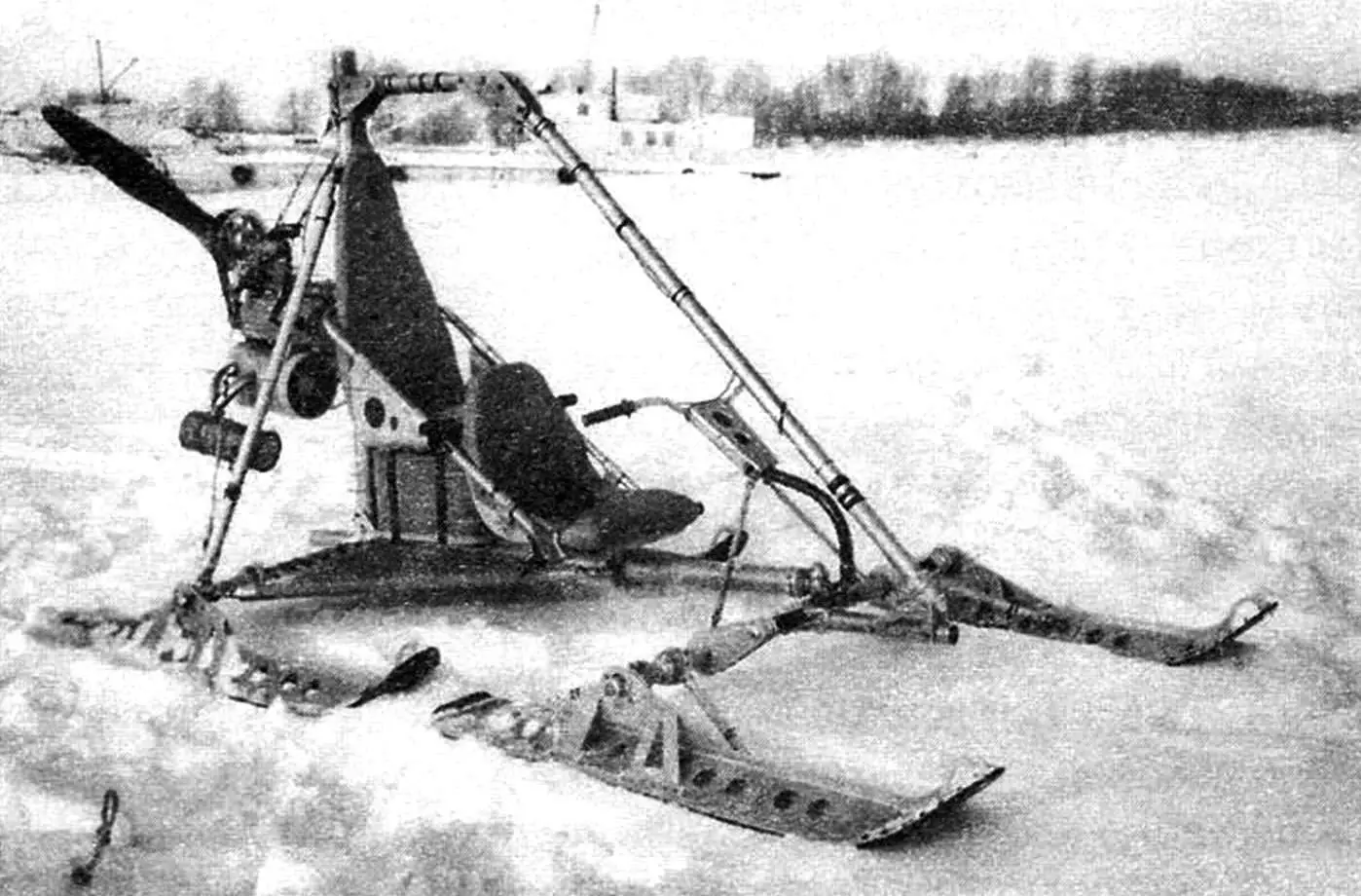
At the time I decided to build an aerosled, I didn’t plan any particularly original design solutions for it — the machine was needed as a regular winter vehicle.
However, when I selected the necessary units, materials, and got down to work, ideas for various design solutions for some components began to emerge. I even had to suspend work on building the aerosled for some time and “think through” the entire design again — on paper. As a result, some solutions turned out to be not only unconventional (perhaps not new, but quite forgotten and not found in modern machines), while others were completely original. I’ll note the design features.
First — the suspension of the power unit (rather than its installation, as usual). Second, “cart-type” steering — it is accomplished by turning not only the skis, but the entire front axle. And finally. The return of the steerable axle with skis to the initial position and keeping it on a straight course are accomplished not so much by the steering wheel, but by a torsion bar, which is played by the safety arch.
Describing the aerosled design, I’ll immediately note: due to the lack of argon welding, all connections of parts in the units had to be made bolted using bushings and brackets, and in some places riveted.

1 — engine (from Buran snowmobile); 2 — V-belt four-groove transmission (i = 1.85); 3 — air propeller Ø1400 (wood with metal end caps); 4 — cantilever beam; 5 — upper engine mounting cable (steel cable Ø4, 2 pcs.); 6 — main post (tube Ø70×2.5); 7 — bracket for connecting safety arch to post (sheet s5, 2 pcs.); 8 — upper part of safety arch (tube Ø50×2); 9 — throttle cable attachment to safety arch (rubber, as needed); 10 — connecting bracket for safety arch parts (sheet s5, 2 pcs.); 11 — inclined part of safety arch (tube Ø50×2); 12 — longeron (tube Ø70×2.5); 13 — steering wheel (motorcycle type); 14 — central steering post (steel tube Ø28); 15 — lateral steering post (tube Ø14, 2 pcs.); 16 — safety arch silent block (from washing machine); 17 — connection unit of safety arch and front axle (sheet s5, 2 pcs); 18 — extension (tube Ø30×1.5); 19 — lateral post brace (tube Ø40×1.5, 2 pcs.); 20 — rear passenger seat (foam in fabric cover); 21 — rear seat base (sheet s5); 22 — handrail-brace (tube Ø30×1.5, 2 pcs.); 23 — front seat base (sheet s5); 24 — front seat (foam in fabric cover); 25 — throttle cable (from motorcycle); 26 — lower engine mounting cable (steel cable Ø4, 2 pcs); 27 — tender (2 pcs); 28 — fuel tank (20 L); 29 — tail-hitch (tube Ø64); 30 — rear axle; 31 — rear ski (2 pcs); 32 — platform attachment (cord, 2 pcs.); 33 — platform (avizent fabric, 2 pcs.); 34 — front steerable axle beam (tube Ø40×1.5, 2 pcs); 35 — front ski (2 pcs.)
The aerosled frame is of backbone type — single-longeron. The rear axle beam and engine mount post, joined and connected to the longeron, are reinforced with braces. The connections of the frame’s load-bearing elements are mainly detachable. I made them this way for disassembling the aerosled and the very large frame for compact summer storage.
The longeron and post are made of duralumin tube with a diameter of 70 mm and wall thickness of 2.5 mm, while the rear axle beam and braces are also made of duralumin tube, but with smaller diameter and wall thickness — 40 mm and 1.5 mm respectively. The seat handrails also play the role of engine mount post braces, although they can only be called handrails conditionally — seat bases for the driver and passenger, stamped from 2 mm thick duralumin sheet, are hung on them. The seats themselves are made of thick foam sheet and covered with canvas fabric.
One more element of the aerosled can be attributed to the frame — the safety arch. It is made of two duralumin tube segments with a diameter of 50 mm and wall thickness of 2 mm, joined with overlays. However, it would be better to make the arch from a solid tube (unfortunately, I didn’t have one at the time of manufacture) because it also serves as a shock-absorbing suspension for the front steerable axle and is a kind of brace for the main post. But more about the arch later.
Regarding the steerable axle, as on a cart, I didn’t misspeak. Returning to such an already forgotten steering scheme was prompted by its simplicity, and it also combined very well with the shock-absorbing safety arch and single-longeron frame. The front axle is connected to the front end of the longeron by means of a kingpin and a silent block (rubber-metal bushing), the body of which is inserted into the front hole of the longeron tube. A M22 bolt serves as the kingpin.

1 — longeron; 2 — bracket-clamp for attaching seat frame crossmember and rear axle braces to longeron; 3 — seat frame crossmember; 4 — brace; 5 — ski; 6 — bracket-clamp for attaching braces to rear axle; 7 — bushing for attaching ski brace to rear axle; 8 — rear axle beam (2 pcs.); 9 — post brace (2 pcs.); 10 — seat frame; 11 — main post; 12 — loop for attaching seat base to frame (10 pcs.); 13 — bracket-clamp for attaching seat frame and engine mount to post; 14 — bracket for attaching longeron to main post; 15 — bushing for attaching seat frame to longeron and main post (2 pcs.); 16 — connecting beam strap (2 pcs.)
The connection of the front axle to the safety arch (which is also the torsion bar) is accomplished not directly, but by means of an extension — a tube segment with a diameter of 40 mm and wall thickness of 1.5 mm, cantilever-mounted at the middle of the axle (perpendicular to it). The free (front) end of the extension is also connected to the front end of the safety arch with a “two-cheek” triangular bracket. The extension length was determined experimentally: within 200 — 250 mm. A smaller length worsens “weathervane effect” — the machine’s self-holding on a straight course, while a larger one makes aerosled control difficult (steering wheel turn). By the way, to facilitate steering wheel turning, I later attached a silent block to the end of the torsion bar (although there is the possibility of helping with feet, as on an airplane).
When the steering wheel, and consequently the front axle with skis, turns, the safety arch deflects to the side and also slightly twists. After removing the force on the steering wheel, the arch tends to return to its initial position, keeping the skis on a straight course.

1 — ski base; 2 — backbone brace; 3 — arch; 4 — backbone; 5 — rivet; 6 — front post brace (2 pcs.); 7 — rear post brace (2 pcs.); 8 — housing with rolling bearing; 9 — post; 10 — eye for attaching ski brace to backbone (2 pcs.); 11 — collar with fork; 12 — rear ski brace (2 pcs.); 13 — bushing for attaching brace to axle beam; 14 — footrest bracket; 15 — axle beam; 16 — longeron; 17 — hinge for connecting axle beam and longeron; 18 — bracket for connecting beam and extension; 19 — bracket for connecting extension and safety arch; 20 — footrest
The steering wheel itself is of motorcycle type, only it is mounted on the axle at three points through brace-levers. A throttle control cable runs from the steering wheel along the arch-torsion bar. Skis are mounted on axles at the ends of the front axle (as well as the rear). To protect against lateral impact, the skis are additionally attached to the axles with braces (it would be better with shock absorbers) through bearing bushings: front ones — with two, rear ones — with one (at the rear) and turn in the vertical plane together with the skis.
The skis are homemade — all identical. Riveted from 5 mm thick D16T duralumin sheet with aluminum rivets. To provide stiffness, a longitudinal strip-wall is welded along the middle of the ski, and strip braces are also attached to the wall. The sole is made from 5 mm thick polyethylene sheet, and the width — 10 mm larger on each side. In the bent part of the nose, the sole is attached to the ski with rivets, and along the length it is simply pressed with a steel angle trim, so that the sole doesn’t warp due to thermal expansion difference. A small part of the rear end of the ski together with the sole is also bent upward by 50 mm. At the ends of the axle beams, the skis are mounted on rolling bearings, the housings of which are fixed on the ski posts.
The propulsor installation itself is traditional and consists of a power unit from the Buran snowmobile with 28 hp and a homemade pusher air propeller of constant pitch.
The propeller is 1400 mm in diameter, the blades are wooden with metal caps on the ends. The maximum thrust it creates in place is about 95 kgf, which allows the aerosled to reach speeds up to 70 km/h on the ice of a frozen river. The transmission of torque from the engine to the propeller is accomplished through a four-groove V-belt transmission. The drive pulley diameter is 205 mm, and the driven one is 380 mm, that is, the gear ratio is 1.85. Belt tension is accomplished by turning the eccentric axis in the bushing with subsequent fastening one to the other with a clamp.

1 — eccentric axis; 2 — bushing (steel, tube Ø50×2); 3 — clamp with clamping bolt; 4 — upper stay tie (rubber strap); 5 — upper stays; 6 — cantilever beam (steel tube Ø40×1.5); 7 — hinge axis (bolt M16); 8 — silent block; 9 — bushing-bracket for mounting engine mount on main post; 10 — main post; 11 — engine attachment unit to cantilever beam (4 pcs.); 12 — engine; 13 — bushing post; 14 — bushing brace (2 pcs.); 15 — beam wing (4 pcs.); 16 — engine output shaft; 17 — lower stay (cable Ø4, 2 pcs.); 18 — tender (2 pcs.); 19 — bushing-
spacer (rubber, 4 pcs.)
The power unit mounting on the frame is not quite usual. First, it is not installed on it, but suspended on a cantilever beam and attached to it through rubber bushing-spacers. The cantilever beam is simultaneously a support through which thrust from the propeller is transmitted. Moreover, the beam is connected to the post hingedly through a silent block. The additional engine mounting to the frame is completely unusual — with stays — aviation flexible cables with a diameter of 4 mm with tensioning tenders. Such suspension of the propulsor installation on the frame practically eliminates aerosled vibration.
There is no propeller guard yet. Of course, a rotating propeller is a dangerous thing. But if you make a simplified guard, it can play a “bad joke” on the person operating the sled, and especially on a passenger. Psychologically, they will think they are protected. In reality, the probability of getting injured from a rotating propeller remains. If you’re going to make a guard, then a full one — in the form of a thin grid on both sides and around the circumference.
And so that the propeller doesn’t hit snow, let alone ice, when the rear part of the aerosled dips, a tail was made — a thinner tube is inserted into the rear part of the longeron.
The dry weight of the aerosled is about 140 kg. Fully equipped (two people and 20 L of fuel) — approaches 300 kg. The aerosled has no brakes, stopping is accomplished quite quickly by friction of the ski soles against the snow after releasing the “throttle”.
S. KOCHANOV-SOROKIN
Recommend to read
 THE CAPACITOR IN SOCKET
One way to reduce interference in digital circuits, as is well known, is to install the ceramic capacitors in parallel with the power rails. The closer to the contacts of the chip...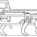 STEPS “HERCULES”
It is a model machine designed to operate in conditions of total off-road on rocky soils. Six powerful metal legs — its propulsion. Thanks to the wide step it can overcome large gaps,...
