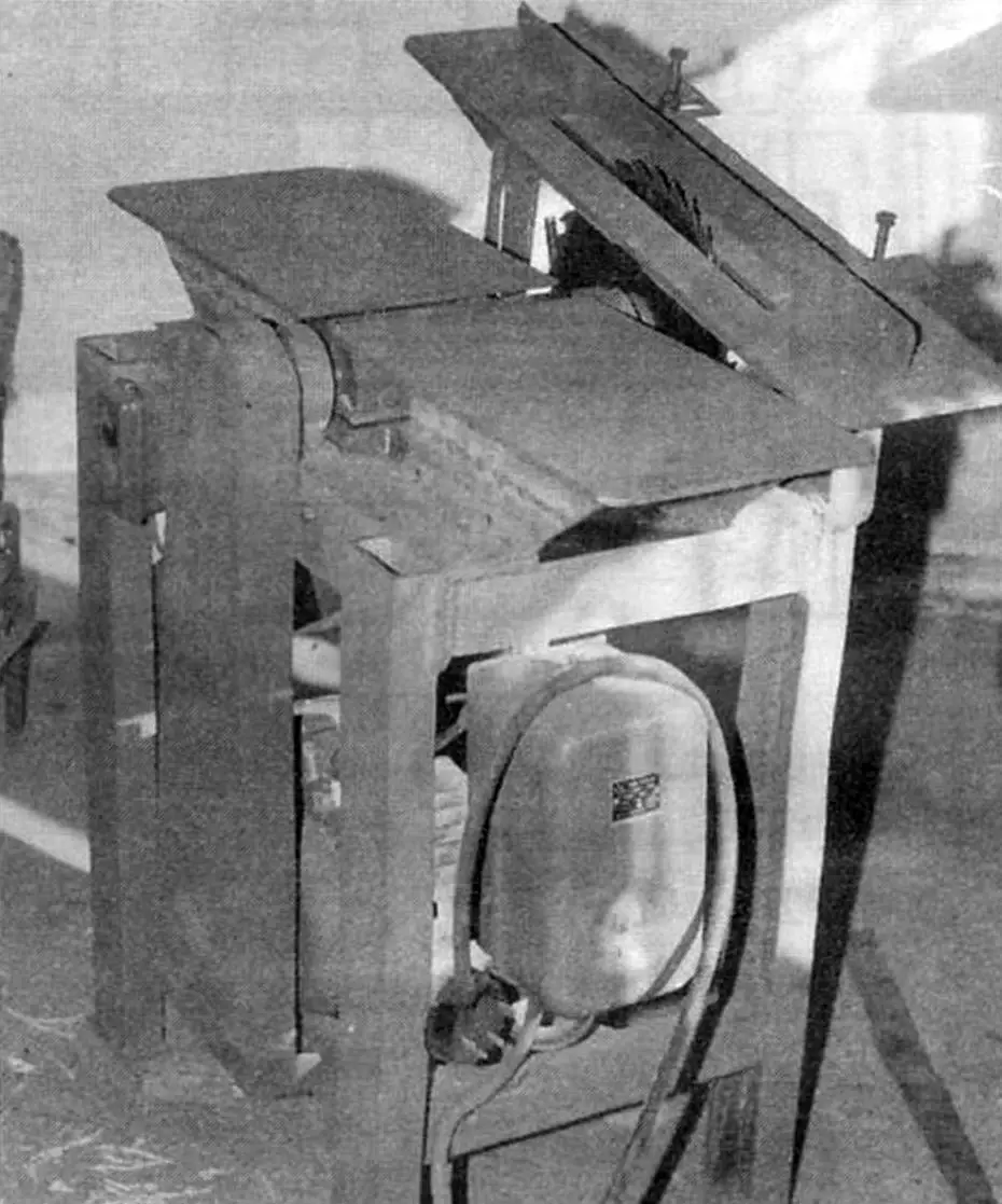
When my family moved to a far from new estate house with a land plot, I faced the problem of its thorough renovation and construction of outbuildings. It was clear that such work could not be handled with hand tools alone. Therefore, I decided that before starting construction, along with a concrete mixer, I would make at least a simple woodworking circular saw/planer machine, which craftsmen call a “circular saw.”
I certainly had a general idea of the design of such machines — I had seen industrial models in stores, and I had also encountered homemade ones (and the latter are no worse). But before manufacturing, I reviewed articles on this topic in magazines, where craftsmen described their original designs.
I started making the machine by purchasing a rotor shaft or, more precisely, — a three-knife planer together with bearings and their housings. It was equipped with double-sided knives, and with a spare set. Making this unit yourself in a home workshop (even with a lathe and milling machine) is not easy. Moreover, good balancing in assembly is required, which can only be performed on a special stand (which no home workshop has), or on a ready-made machine that still needs to be made.
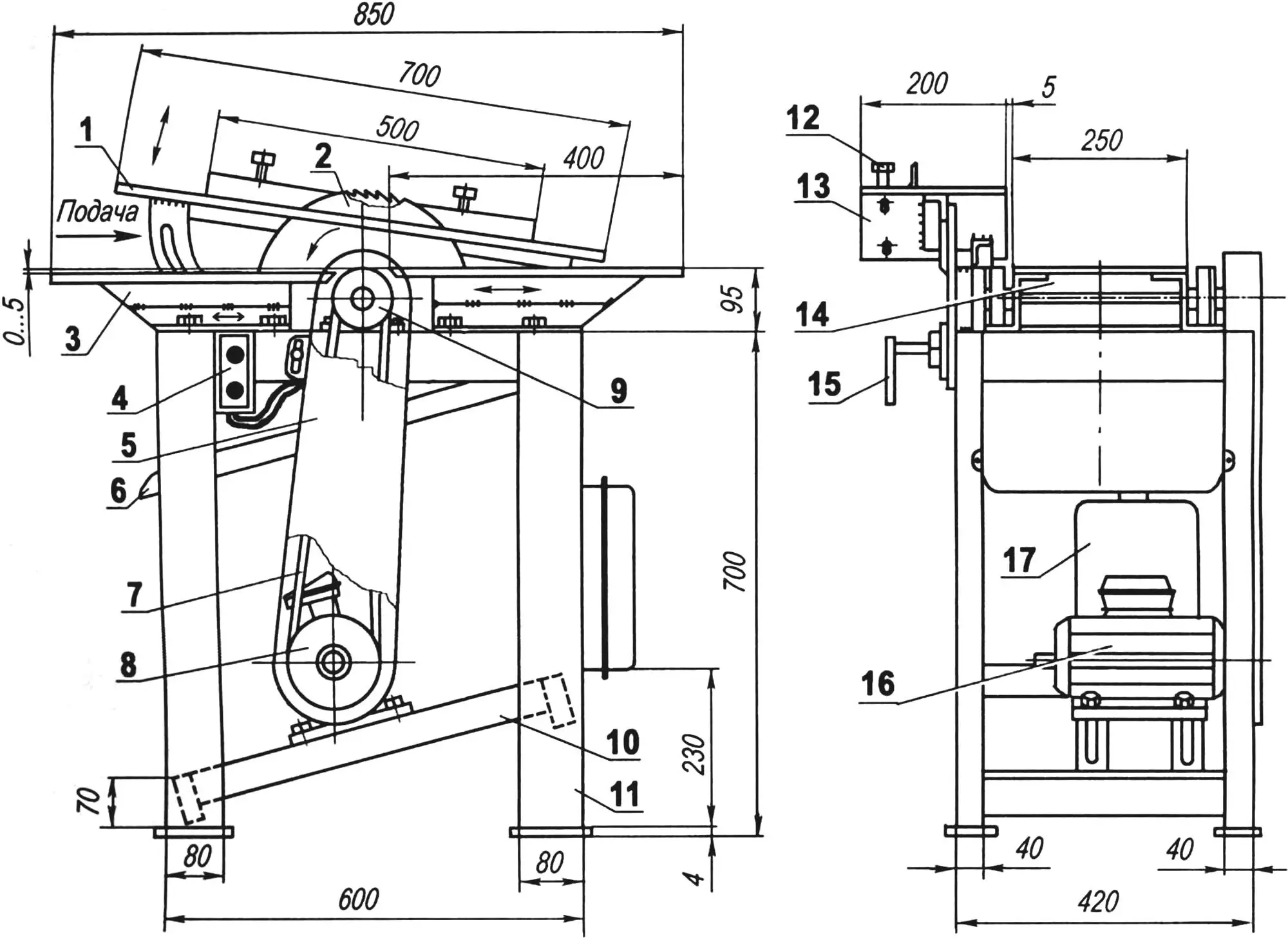
1 — saw table; 2 — circular saw (Ø400); 3 — planer table left, right — mirror image; 4 — electric starter; 5 — drive housing; 6 — tray for sawdust and chips removal; 7 — drive belt; 8 — driving pulley of V-belt drive; 9 — driven pulley of V-belt drive; 10 — electric motor support; 11 — machine frame; 12 — guide fence; 13 — saw table lift hinge; 14 — rotor shaft; 15 — clamp for fixing saw table in raised position; 16 — electric motor (U = 380 V. n=3000 rpm, N = 3 kW); 17 — electrical distribution panel
The machine design, one might say, is classic, although it did not do without original solutions. But more about that — as the story goes.
The machine frame is four-legged. Its base is four legs made from channel No. 8 with base plates to increase the support area. At the top, the legs are connected by longitudinal and transverse ties. The former are made from equal-leg angle 70×70 mm, and the latter — from a similar angle 63×63 mm.
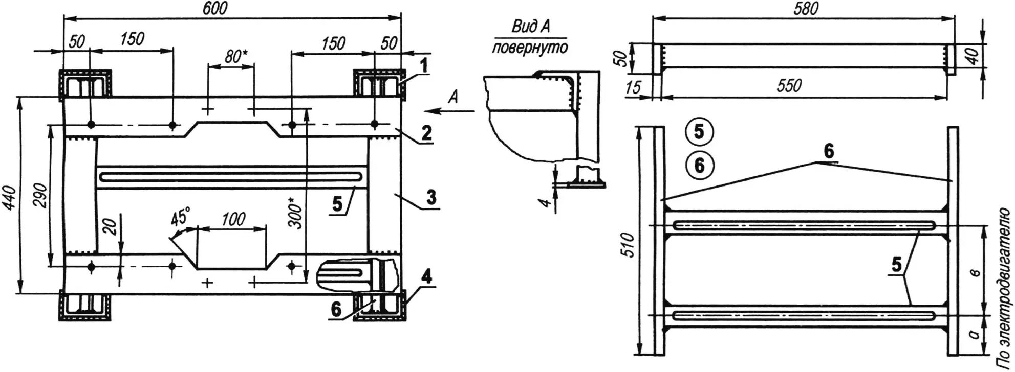
1 — leg (channel No. 8, 4 pcs.); 2 — longitudinal tie (angle No.7, 2 pcs.); 3 — transverse tie (angle No. 6, 3, 2 pcs.); 4 — base plate (steel sheet s4, 4 pcs.); 5 — electric motor support (angle No. 4, 2 pcs.); 6 — transverse electric motor support (strip 50×15, 2 pcs.)
At the same time, the longitudinal ties serve as supports for the planer’s rotor shaft, as well as the outfeed and infeed planer tables. I should note right away that the outfeed planer table is mounted flush with the protruding knife blade (through shim washers or plates), and the infeed table — below this level by the depth of cut.
At the bottom, the legs are connected by transverse and longitudinal electric motor supports. Slots are made in the latter, and they themselves are installed at an angle. By moving the electric motor along them, the tension of the drive belts of the V-belt drive can be adjusted.
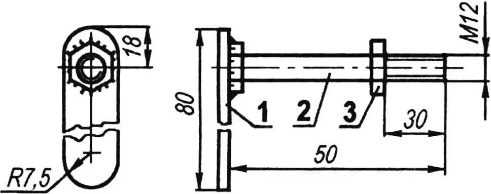
1 — handle (steel strip 3×15); 2 — clamp (bolt M12); 3 — stop (nut M12)
I selected ready-made double-groove pulleys — from some decommissioned agricultural equipment. But I want to say that with such motor power (3 kW) and about 3000 rpm, two belts are not enough — they have to be tensioned too tightly.
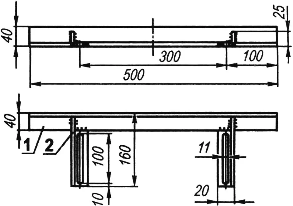
Returning to the planer tables (infeed and outfeed), I note that in design they are mirror images. Z-shaped profiles welded from two sections of equal-leg angles 40×40 mm serve as aprons for them.
1 — table plate (steel sheet s10); 2 — upper part of apron (angle No. 4); 3 — lower part of apron (angle No. 4)
The table plates are welded to the upper flanges of the apron pair, and longitudinal slots are made in the lower flanges for their attachment to the frame’s longitudinal ties with M10 bolts. It is quite possible to make corresponding holes in the flanges instead of slots, only they will need to be drilled together in the table aprons and the frame’s longitudinal ties during machine assembly, having first verified the position of the tables relative to the planer.
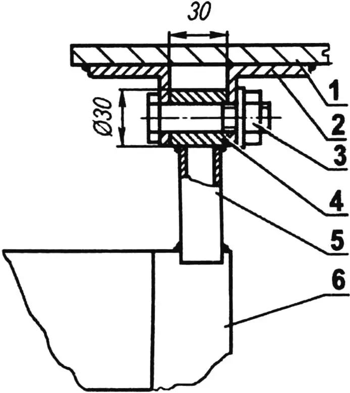
1 — table plate; 2 — axis bracket; 3 — axis (bolt M12); 4 — spacer bushing (steel, round 30); 5 — bushing stand (rectangular tube 30×20); 6 — frame leg
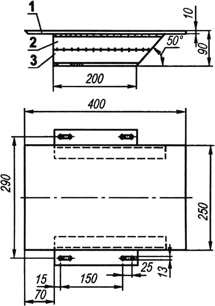
The saw table at first glance also seems ordinary. But it has an original mechanism for adjusting its raising-lowering to set the cutting depth. This operation is performed by loosening and then tightening just one clamp — an M12 bolt, which I also equipped with a handle and manage without wrenches.
1 — fence (angle 40×40); 2 — bracket (angle 25×25, 2 pcs.)
The saw table is a plate made from a 10-mm steel sheet. A reinforcement made from a 35×35 mm steel angle is welded to the bottom of the plate. At one end of the reinforcement, a table lift adjustment sector is welded to it and to the plate, and near the other end — a bracket made from the same angle. Holes for the saw table attachment axis to the frame are made together in both parts. The axis is an M12 bolt inserted into a bushing stand welded to the frame. The saw table is equipped with an adjustable guide for workpieces, made from an equal-leg angle 40×40 mm.
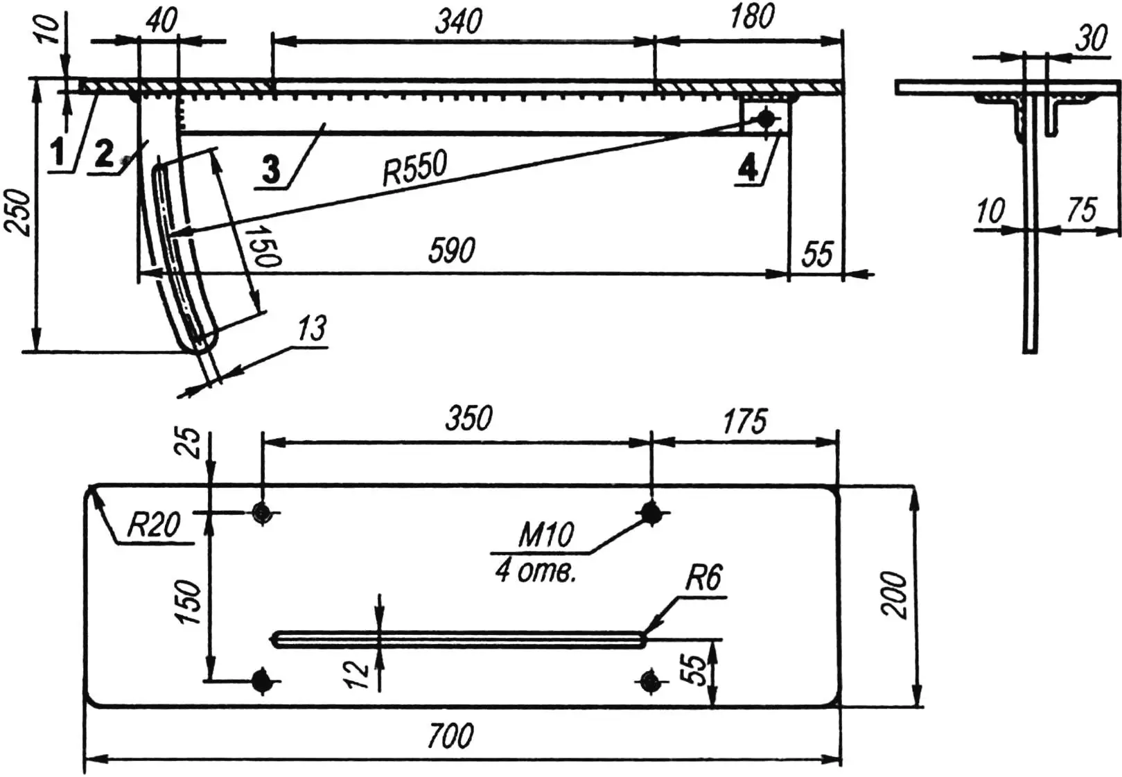
1 — plate (steel sheet s10); 2 — sector (steel sheet s10); 3 — reinforcement (steel angle 35×35); 4 — axis bracket (angle 35×35)
Finally, a tray made of thin steel or duralumin sheet for collecting sawdust and chips is mounted under the planer shaft. The tray slope — in any convenient direction.
The electrical circuit is standard for a 3-phase electric motor — it has been shown more than once on the pages of the “Modelist-Konstruktor” magazine and there is no need to repeat it. I will only remind that the switch should be in an easily accessible place. The drive must be covered with a housing and safety precautions must be strictly observed when working on the machine.
“Modelist-Konstruktor” No. 12’2007, A. MATVEYCHUK
Recommend to read
 CHOCOLATE STORAGE BOX
Every home handyman tries to have a stock of various mounting small items — nails, screws, bolts, nuts and washers. For them it is necessary to use a variety of boxes, jars, vials....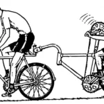 BICYCLE TRAILER? TANDEM!
Many outdoor enthusiasts prefer cycling trips to other forms of short travel, such as hiking or driving. Walking allows you to fully enjoy the beauty of nature and take in the...
