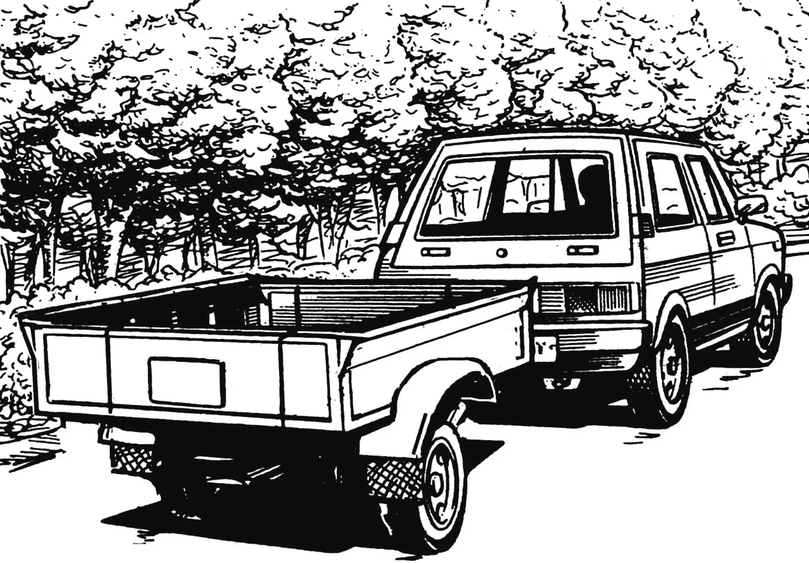
Many builders — future homeowners or summer residents — have to solve the issue of transporting local building materials over short distances, such as soil, sand, stone. Some owners, having their own transport equipment (car, tractor, or even a walk-behind tractor), buy a trailer for it. However, the price of an industrial trailer is such that a thrifty owner, especially if he is a craftsman, will definitely consider: why not make such a trailer yourself? This is for such craftsmen that another cargo trailer design is offered.
Let us immediately note: the trailer design is simplified — it has no brake device and signal lights. Therefore, for transportation on public roads without additional equipment with the above devices, the trailer cannot be operated.
The trailer is single-axle, two-wheeled, with folding front and rear sides.
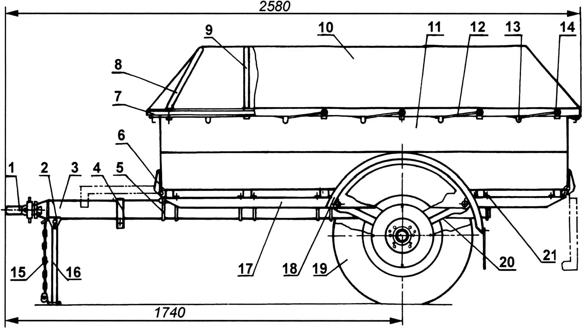
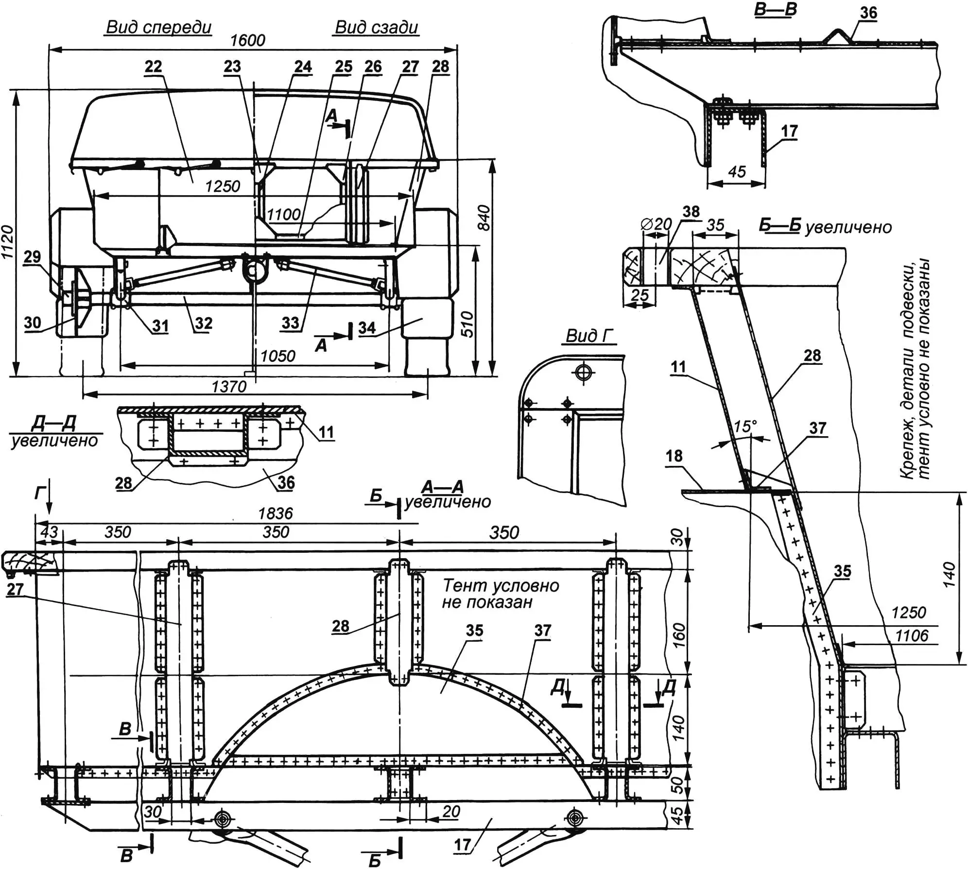
1 — locking device; 2 — support post and safety chain bracket; 3 — drawbar (duralumin tube Ø80×3); 4 — bracket for holding support leg in transport position (spring steel, strip 10×2); 5 — stirrup M8 with washers and nuts (St3, rod Ø8, 8 pcs.); 6 — folding side hinge (8 pcs.); 7 — bumper bar (board 90×30); 8 — inclined tent arch (duralumin tube Ø19×1.5, 2 pcs.); 9 — straight tent arch (duralumin tube Ø19×1.5, 4 pcs.); 10 — tent (waterproof fabric or tarpaulin); 11 — side wall (duralumin, sheet s1.5, 2 pcs.); 12 — rope for securing tent to body (Ø10); 13 — hook for rope attachment (St3, sheet s1.5, 20 pcs.); 14 — reinforcing ring (tin s1.5, 20 pcs.); 15 — safety chain; 16 — folding post (square tube 25×25); 17 — side member (bent channel 45×45, duralumin sheet s2, 2 pcs.); 18 — fender (duralumin, sheet s1.5, 2 pcs.); 19 — wheel (from “Moskvich” or “Zhiguli” car, 2 pcs.); 20 — strut (steel tube Ø30×2, 4 pcs.); 21 — body frame cross beam (bent channel 50×20, duralumin sheet s3, 12 pcs.); 22 — outer sheathing of front (and rear) side (duralumin, sheet s1); 23 — middle gusset of folding side frame (St3, sheet s1.5, 4 pcs.); 24 — side frame post (square tube 20×20, 6 pcs.); 25 — front (and rear) side frame binding (square tube 20×20); 26 — end gusset of folding side frame (St3, sheet s1.5, 8 pcs.); 27 — body posts (U-shaped profile 66×42 with flanges (b = 15, duralumin, sheet s1.5, 6 pcs.); 28 — over-wheel body post (duralumin, sheet s1.5, 4 pcs.); 29 — hub (steel 30KhGSA, round Ø62, 2 pcs.); 30 — hub flange (steel 30KhGSA, sheet s20); 31 — clamp bracket for attaching struts to beam; 32 — axle beam (steel tube Ø50×3); 33 — cross tie (steel tube Ø30×2, 2 pcs.); 34 — mudguard (rubber, sheet s5, 2 pcs.); 35 — wheel well insert (duralumin, sheet s1.5, 2 pcs.); 36 — floor (duralumin, sheet s1.5); 37 — fender bracket (duralumin, sheet s1.5, 2 pcs.); 38 — bumper bar bushing (as required)
The body has its own separate frame and is a self-supporting structure. It is rigidly mounted on the axle beam — on longitudinal struts and transverse ties. Of course, one could proceed more simply: weld the drawbar directly to the middle of the beam, and attach the body frame to the resulting T-shaped frame. But such a layout would deprive the possibility or significantly complicate further trailer modernization (if it is necessary to equip it with a soft suspension). With the existing design, this modification option can be implemented quite easily by replacing the longitudinal struts with springs and the transverse spacers with shock absorbers.
Damping of impacts, jolts, and vibrations from road irregularities is carried out by wheel pneumatics and rubber bushings of silent blocks in the struts. Moreover, the greater the cargo mass, the smoother the trailer runs.
The body frame base: two side members and five cross beams on them. Such a relatively large number is dictated by ensuring the rigidity of the body floor. For the same reason, there are also five posts on the longitudinal sides of the body.
The side members and cross beams are bent from 3 mm thick duralumin sheet in the form of a channel with dimensions of 45×45 and 50×20 mm, respectively. The side members and beams are fastened together with M8 bolts with spring washers. The connections of duralumin body sheets (except the bottom) with power elements are made with 3 mm diameter aluminum rivets with a semicircular head.
The side posts are bent from 1.5 mm steel sheet, also in a U-shaped form, but with flanges, with which they are riveted to the sides. Above the wheels, these posts are shortened. The sides and bottom of the body are made of 1.5 mm duralumin sheet. Several stiffening ribs are embossed on the bottom. The bottom is riveted to the frame cross beams with countersunk head rivets. The side sides are slightly wrapped around the ends at the front and rear, giving additional rigidity to the body.
The side sides are made with a slight divergence of the walls upward. This position ensures loading of bulk materials without excessive losses. Moreover, with a relatively small track (wheels should not protrude beyond the vehicle dimensions), it was possible to avoid wheel wells inside the body. The rear side, like the front, is folding. This allows unloading most of the bulk materials from the trailer by “dump truck” method — by shifting the center of gravity of the load (the drawbar is disconnected from the tractor and raised up for this). By folding the front side onto the drawbar and the rear one at 90° and securing it in this position with stays, long-length lumber, pipes, etc. can be transported on the trailer. The folding sides have their own frames made of 20×20 mm square tube, sheathed on the outside with 1.5 mm thick sheet.
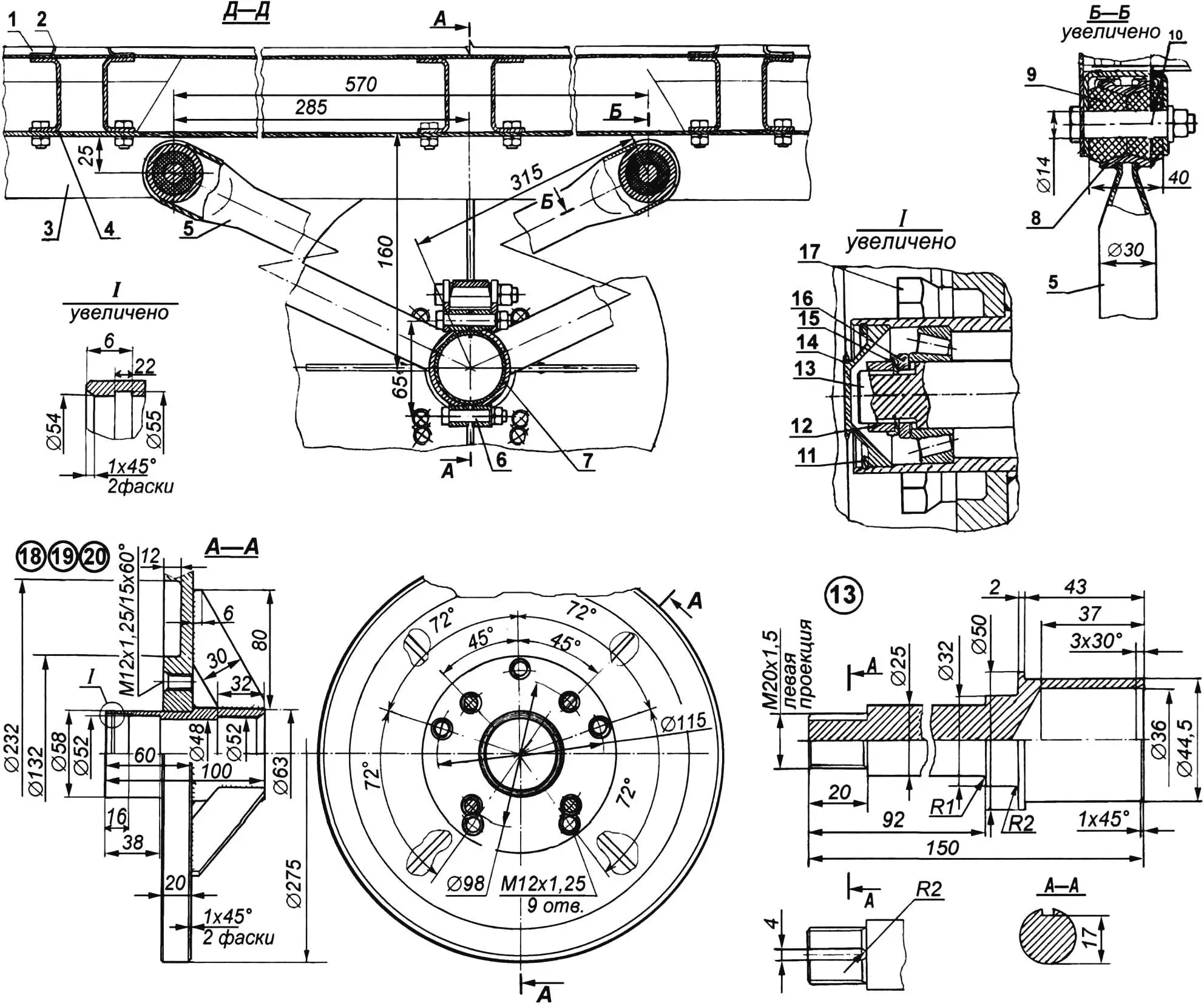
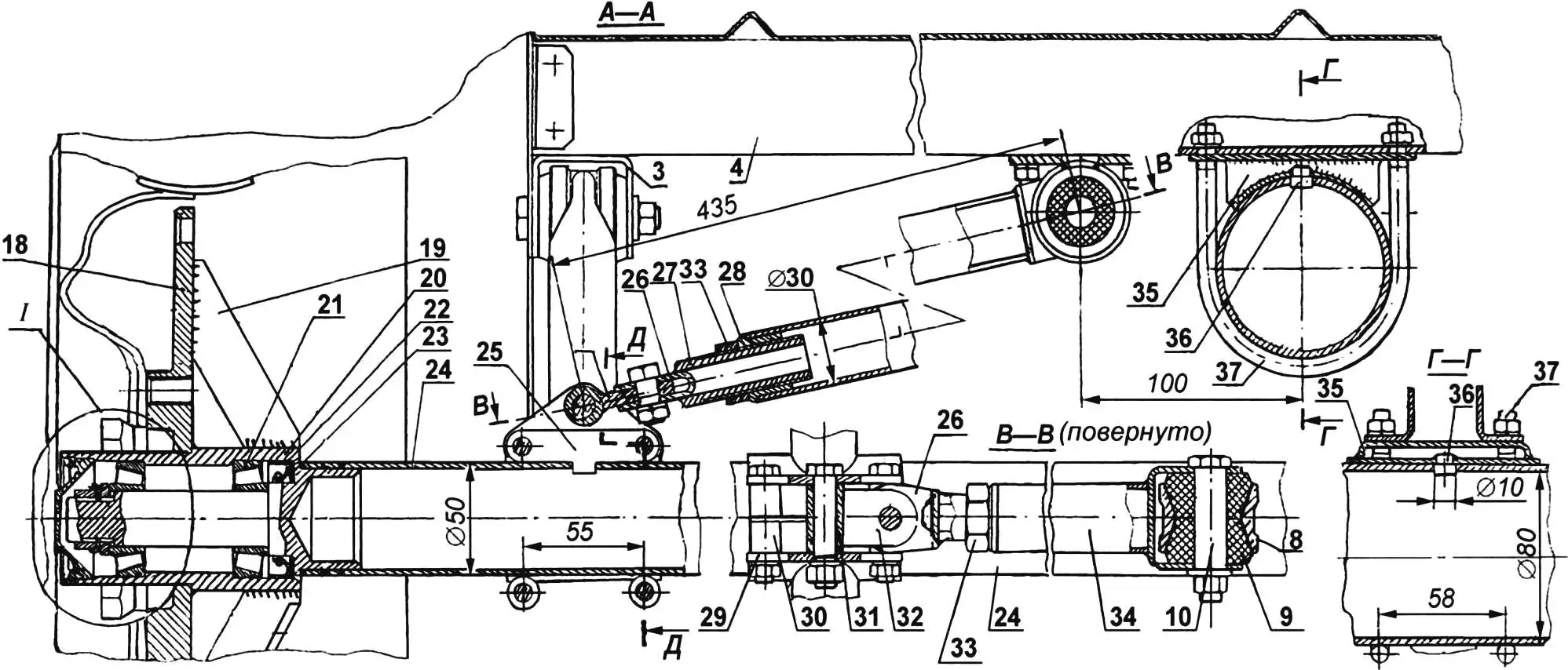
1 — body floor; 2 — body post; 3 — side member; 4 — cross beam; 5 — strut; 6 — tie bolt M8 with spring washer; 7 — clamp bracket half-ring (steel 30KhGSA); 8 — strut silent block housing (steel 30KhGSA, tube Ø40×5, 4 pcs.); 9 — strut silent block bushing (rubber, 4 pcs.); 10 — silent block axle with M10 nut and washer (6 pcs.); 11 — lock ring (steel 50KhFA, sheet s2, 2 pcs.); 12 — lock nut M20x1.5 (2 pcs., on right side — with right-hand thread, on left — with left-hand thread); 13 — bearing journal for 7205 bearings with M20x1.5 thread (2 pcs., on right side — with right-hand thread, on left — with left-hand thread); 14 — plug (D16T, round Ø54, 2 pcs.); 15 — lock washer (steel 20, sheet s2); 16 — adjustment nut M20x1.5 (2 pcs., with right and left thread); 17 — wheel mounting screw M22x1.5 (4 or 5 — depending on model); 18 — wheel mounting flange (steel 30KhGSA, sheet s20, 2 pcs.); 19 — flange rib (steel 30KhGSA, sheet s5, 8 pcs. — 4 pcs. per disc); 20 — hub (steel 30KhGSA, round Ø62, 2 pcs.); 21 — bearing 7205 (4 pcs. — 2 pcs. per hub); 22 — seal (2 pcs.); 23 — dust cover (St3, sheet s2, 2 pcs.); 24 — axle beam (steel 30KhGSA, tube Ø50×3); 25 — lock insert (steel 45, sheet s2.5, 2 pcs.); 26 — spacer connecting fork (St3, sheet s2.5, 2 pcs.); 27 — adjustment bushing M20x1.5 (steel 30KhGSA, tube Ø20×4, 2 pcs.); 28 — adjustment nut M20x1.5 (steel 30KhGSA, 2 pcs.); 29 — clamp bracket cheek (steel 30KhGSA, sheet s4, 2 pcs. per bracket); 30 — lock insert bushing (St3, tube Ø14×2, 2 pcs. per bracket); 31 — spacer connecting bracket bushing (St3, tube Ø16×3); 32 — spacer connecting bracket lug (St3, sheet s6); 33 — lock nut M20; 34 — spacers (steel tube); 35 — cradle (St3, sheet s2.5, 5 pcs.); 36 — lock boss (St3, round Ø10, 5 pcs.); 37 — stirrup
A bumper bar is installed along the upper edge of the sides. The side walls are attached to it at the top. Arches serving as support for the removable tent, made of dense waterproof fabric, are inserted into its holes. The tent is secured to the body sides using a nylon rope passed through ringed holes and hooked onto hooks on the outer side of the body sides.
The trailer loading height (distance from ground to body floor) turned out to be relatively small — 510 mm.
Bearing journals for 7205 bearings are welded to the ends of the axle beam — a steel tube with a diameter of 50 mm and a wall thickness of 3 mm. There are two on each journal. Tapered bearings are chosen because a loaded trailer has high axial loads when driving off-road. Moreover, such bearings can be “tightened” — adjusted — over time if necessary. Hubs with flanges welded to them for wheel mounting are installed on the bearings. Each flange is reinforced with four ribs welded on the inside to both the flange and the hub. Two groups of threaded holes M12x1.25 are made in the flange: four holes for mounting VAZ wheel discs and five holes — for “Moskvich”. It is hardly advisable to take wheels from passenger cars of a smaller class for such a heavy-duty trailer.
The connection of the beam with the body frame, as mentioned earlier, is rigid. It is carried out by two identical longitudinal struts (in place of springs in conventional trailers) and a transverse spacer (in place of a shock absorber) on each side. These parts are made of 30×2 mm steel tube. The upper ends of the struts are attached directly to the side members through silent blocks. The lower ends are welded to the clamp bracket half-ring. The half-rings on the beam are tightened with M8 bolts, and to prevent rotation, a steel gasket with a tab is placed in the bracket from above, which is inserted into a rectangular hole in the beam tube.
The lower end of the transverse spacer is also attached to this clamp by means of a specially provided M10 bolt for this purpose. The upper end of the spacer is secured through a silent block in a bracket mounted on the middle cross member of the frame. The spacer is made with a threaded bushing in the lower part, which allows the necessary adjustment of the tie length.
The trailer drawbar is made from a duralumin tube with a diameter of 80 mm and a wall thickness of 3 mm. It is pulled to the frame cross members with M8 stirrups. Steel cradles for this tube are pre-fitted on the stirrups. Lock bosses are welded to the cradles, and corresponding holes are drilled in the tube wall — to prevent the drawbar from being pulled out.
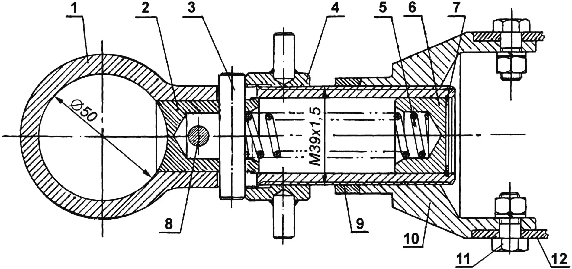
1 — lock (steel); 2 — bushing (steel 30KhGSA, round Ø30); 3 — pin (steel 30KhGSA, round Ø10); 4 — special nut M39x1.5 with two thrust pins (steel 30KhGSA, round Ø50); 5 — coil spring; 6 — plug (D16AT, round Ø30); 7 — lock ring (steel 50KhFA, sheet s1.2); 8 — lock bolt M8 (steel 30KhGSA); 9 — lock nut M39x1.5 (steel 30KhGSA); 10 — connecting bushing (steel 30KhGSA, round Ø80); 11 — bolt M8 (2 pcs.); 12 — drawbar
The coupling lock design must correspond to the tractor’s hitch, but in any case, it must be made as a damping device — to dampen jerks and jolts transmitted from the tractor to the trailer and vice versa. It would not be superfluous to equip it with a safety chain, and the drawbar — with a folding support leg.
The main advantage of the trailer is that you can load as much inert materials (sand, crushed stone, soil) onto it as will fit in the body. Just so the wheels hold up and the tractor can handle it. In general, the trailer is a real heavy-duty one.
E. YEVSIKOV
Recommend to read
 THE GRIP ON THE LEASH
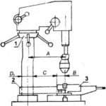
Bench drilling machines (such as NA-10, NA-12), as a rule, is at any station of young technicians in every school workshop. There are some in our school (I work as a teacher). And once a... THE BOLT CAP
Under certain operating conditions (e.g., vibration) threaded connections progressively'm quite unhinged by it. To avoid this, do not have to screw the lock nut: its role can play and a...
