ANTENNA IN HASTE

ANTENNA IN HASTE

Anyone who at least once in a lifetime chance to deal with wires, you can make original TV antenna (Fig.1) no worse than industrial zigzag.
The idea of this simple device I made in the years of his student life. The antenna was so successful that they continue to use it. The familiar “spread”, and they liked the design, which was given the name “Student”.

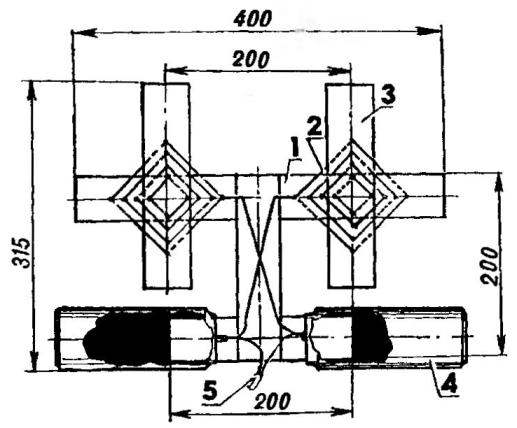
The frame design is made up of an ordinary wooden ruler: 400-mm clerical and four 200-mm pupils. The upper part of the antenna is a copper wire, passed through a cruciform system of holes formed in the frame drill 2 mm diameter with a pitch of 10 mm.
 
TV Antenna
Fig.1 TV Antenna “Student”:
 
1 — wooden ruler stationery (L400); 2 — copper wire Bette insulation d2; 3 — wooden disciplic line (L200-4 pieces); 4 cans; 5 — coaxial antenna cable

 
The lower part is two cans of beer attached to the line of glue. The tabs soldered cans lived and winding of the antenna cable and wires from the top of the antenna.
 
However, more experienced homebrew more interesting, apparently, a zigzag antenna that stood the test of not one dozen years. Initially it was calculated for the reception of television stations using channels from I to V. in order For such an antenna will work for VI—XII the channels specified in figure 2, the dimensions must be reduced by 3.6 times.
As in the first embodiment, requires first of all the wire and cross the United bars: one vertical cross section of 60×60 mm and two horizontal cross-section 40×40 mm. is mounted this design on a wooden mast, and the top bar should defend from the top at a distance of not less than 1100 mm.
 
Vertical bar top and bottom are nailed (or even better — are screwed) on metal lath. Same strap, but on insulating strips (for example, from organic glass) are fixed on the ends of the slats. But the Board of insulating material, located strictly in the middle between the rails, strengthened two rounded metal plate.
 
Zigzag TV antenna
Fig.2 Zigzag TV antenna:
 
1 — mast (wood block, 60×60); 2 — metal strip (6pcs): 3 — rail (wooden bar 4040, 2ші.);4 insulation pad (4 PCs); 5 — coils of wire or antenna cord; 6 — PCB; 7 — feeder line (coaxial cable or on digital signature using rkz)

 
After installing the modules and Board in a zigzag stretch of three parallel wires with a diameter of 2-3 mm or the antenna cord. To bend the ground wire soldered to the strips and plates. Coaxial
cable with wave resistance of 75 Ohm is tied to the mast and then (one of the inner wires of the antenna) is stretched to the Board. Its braid is soldered to one of the rounded plate PCB, connected with wire, which stretched “coax”, and core — to another.
K. KHLEBNIKOV, Krasnoyarsk

Recommend to read

  • TRANSPORTATION, STRETCHING INTO TOMORROWTRANSPORTATION, STRETCHING INTO TOMORROW
    Many readers were interested in the material "Migomobile — fantasy? Reality!" (1977, No. 11), tells about an unusual engine for transport — the flywheel developed by a group of young...
  • LASER ASSISTANTLASER ASSISTANT
    As a longtime reader of Your magazine, a lot of interesting in this read. Finally, I decided to write myself: maybe useful to someone my experience of construction. Its essence is as...