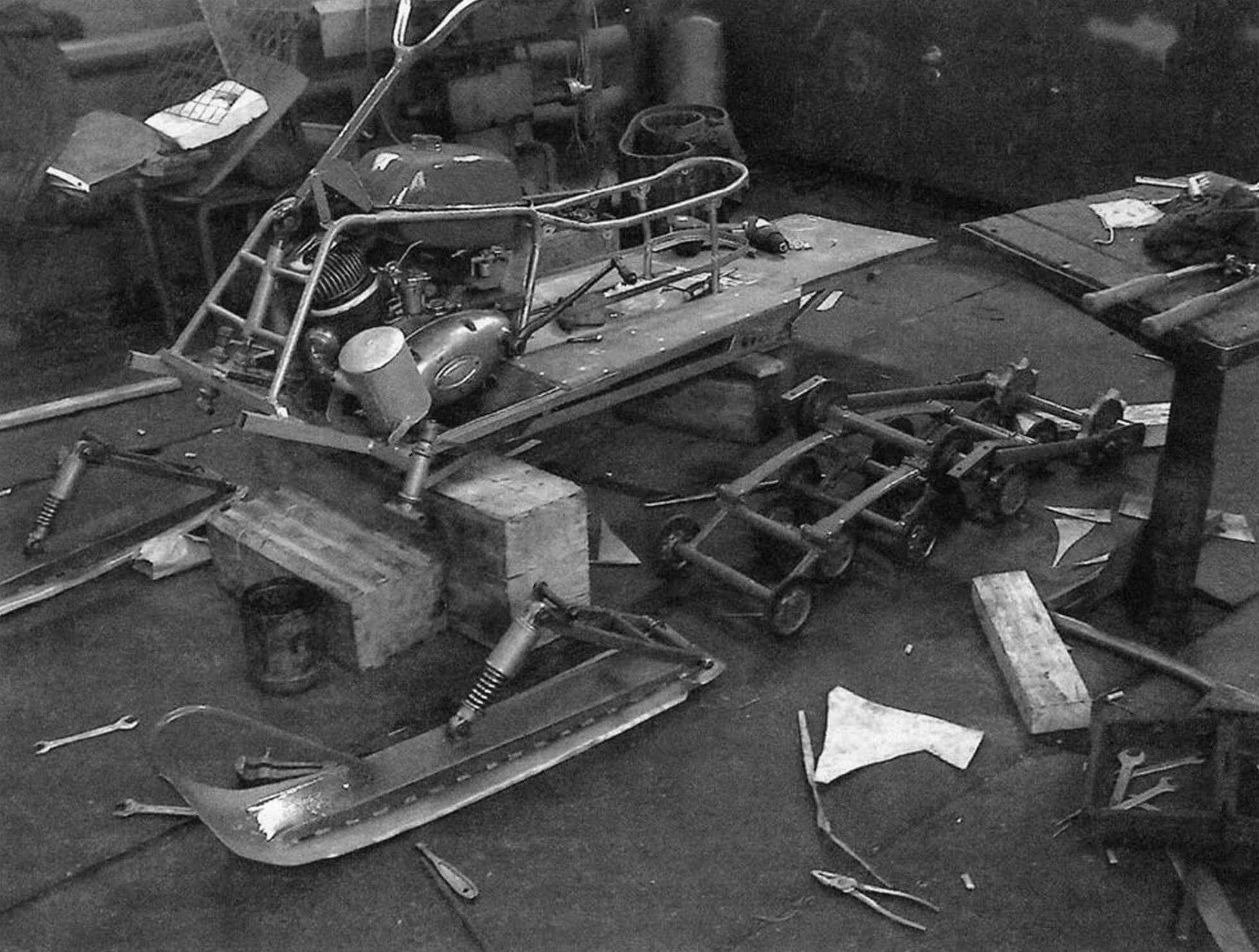
Remembering the history of the creation of the snowmobile, I realized how long ago my passion for designing equipment began.
Even in my youth (and now I’m already a pensioner), I received the specialty of a mechanic and independently mastered welding and other metalworking specialties. But, to be honest, I couldn’t “boast” of my design knowledge, and there was nowhere to learn. On a whim, I built all sorts of “tricksters” on wheels and tracks: I drove them off-road and in the snow, but there was neither reliability nor beauty in them.
But at the beginning of 1988, “Model Designer” was published, which contained an article about the snowmobile “Caterpillar around the ski.” This is where it started!
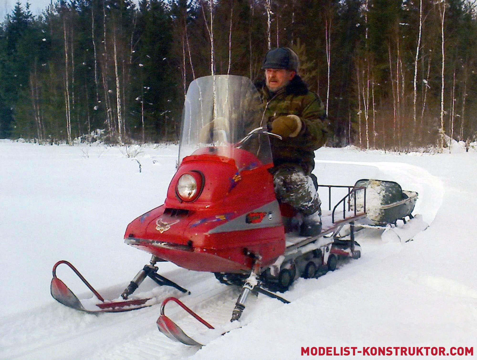
Our places are such that the snow cover lasts for six months or even more! Local roads are usually not cleared on time, and only in such a way that only an all-terrain truck can pass. Well, there’s nothing to say about country roads. In addition, I had hobbies: hunting and fishing. All this motivated me to make a good, passable snowmobile.
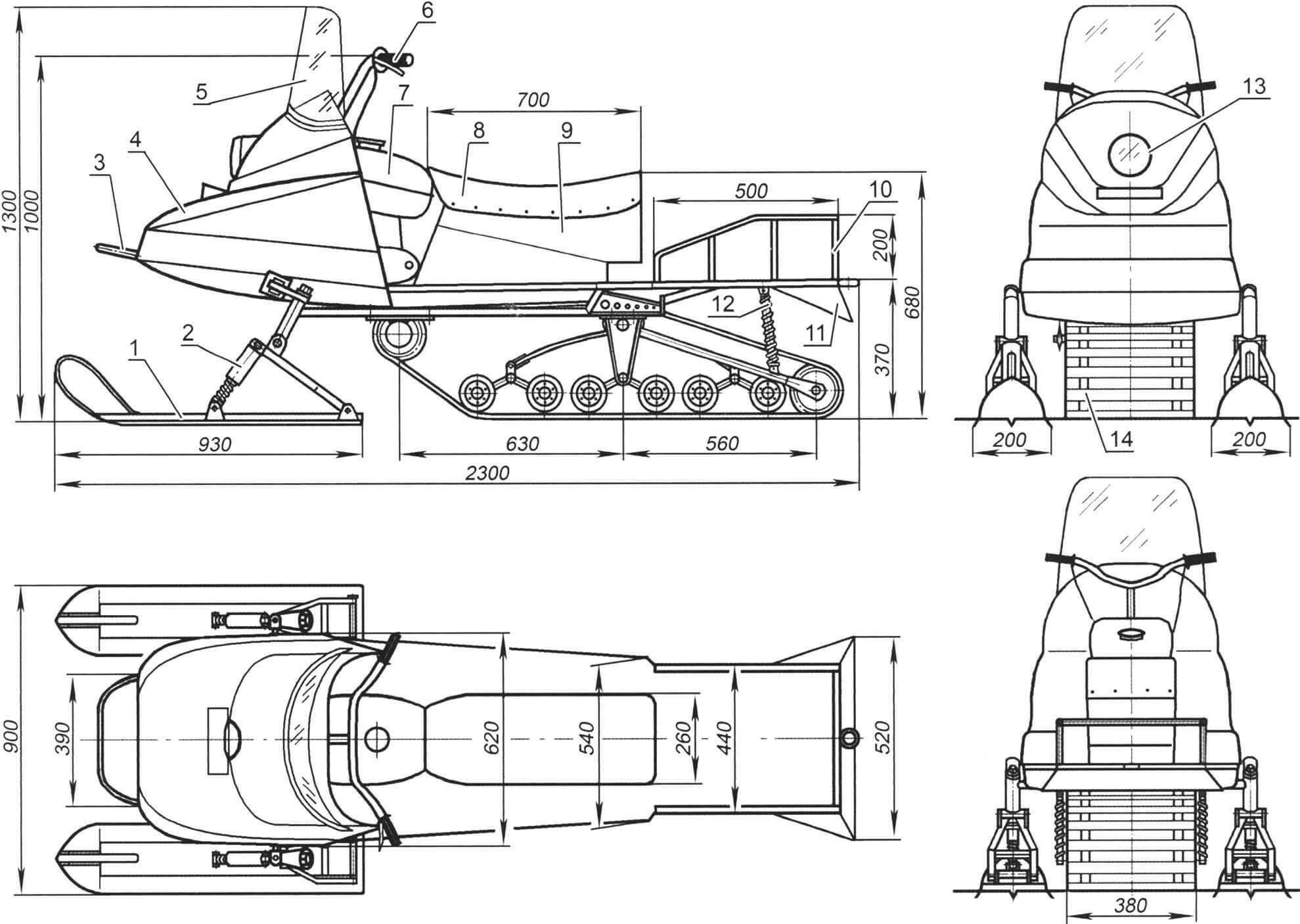
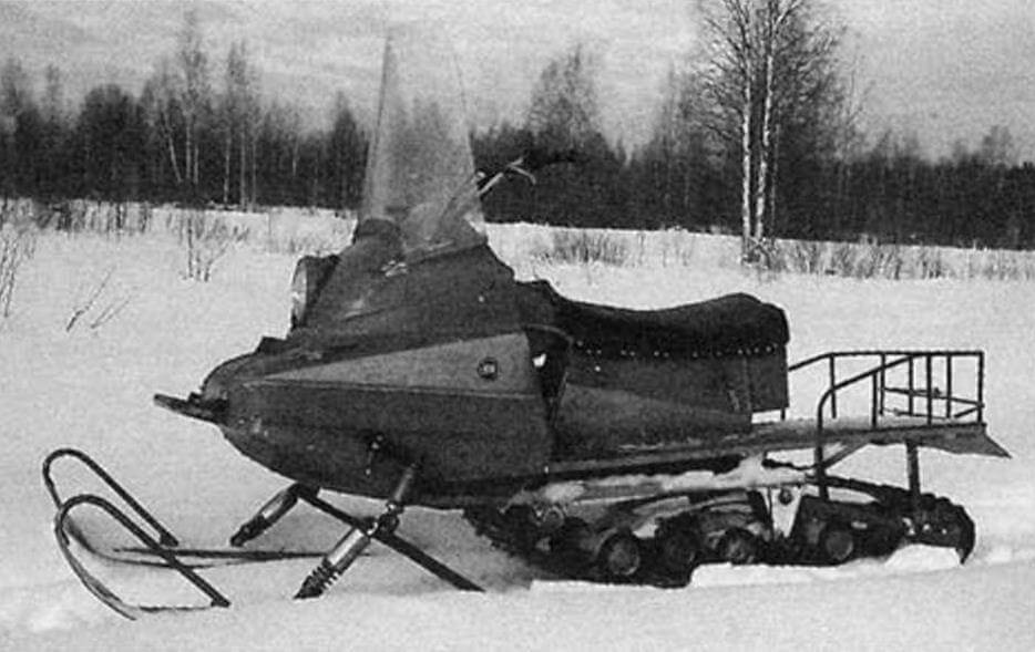
1 — controlled ski (2 pcs.); 2 — steering ski suspension (2 pcs.); 3 — arc (pipe Ø32); 4 — hood (from the side trailer of the Java motorcycle); 5 — windshield; 6 — steering wheel; 7 — fuel tank (welded from two moped tanks); 8 — seat; 9 — tool box; 10 — trunk fencing (pipe Ø16); 11 — mudguard (steel sheet s0.5); 12 — spring shock absorber for the suspension of the tension pendulum arms of the tracked unit (2 pcs.); 13 – headlight; 14 — tracked block
I built it for myself, helped friends and family, and gained experience. He constantly improved the design “according to the laws of evolution”: he replaced heavy with light, unreliable with durable, introduced suspensions: leaf springs, springs, shock absorbers. In total, he built more than a dozen snowmobiles: on tracks with wooden and polyethylene tracks around glide skis; rubber with roller block; both with one control ski and with two.
But I’ll tell you about my last snowmobile. I can’t say that it doesn’t have shortcomings, but I put all my accumulated experience into its design and the car turned out to be successful, although without frills (or, as they say now, utilitarian), but it looks good, and the reliability is height.
The layout of the snowmobile was chosen to be the most common, both on similar domestic machines and on foreign ones: two front steerable skis; power unit located in front under the hood; Next is the track block, and above it is the seat and behind it is the trunk. The total length of the snowmobile is 2300 mm, the width at the outer edges of the skis is 900 mm, the height to the steering wheel is 1000 mm, and to the seat is 700 mm.
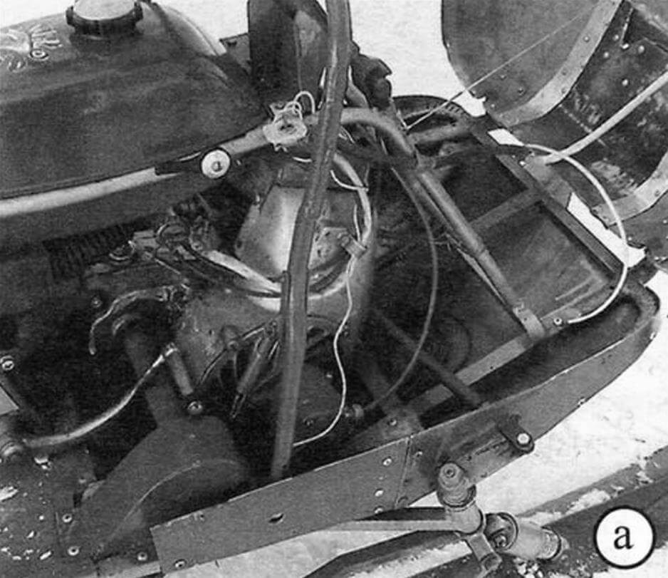
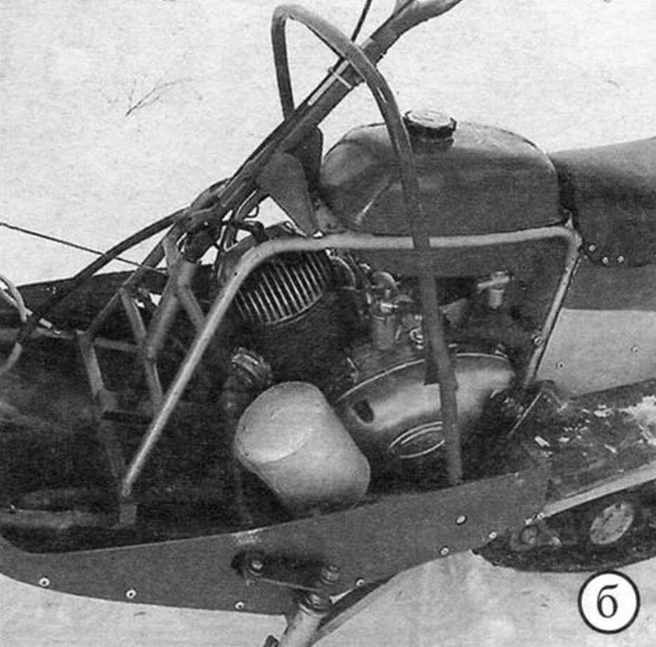
a — view from the right; b – left view
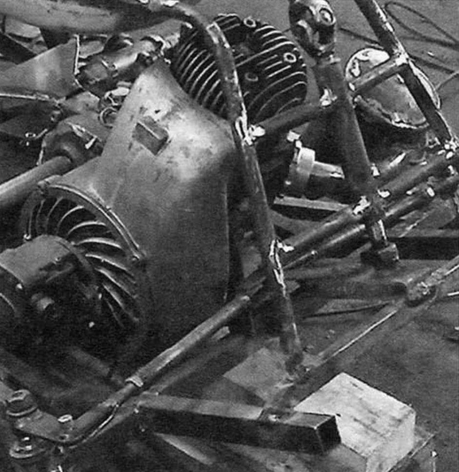
The power unit (engine, clutch and gearbox in one unit) is “Tula-200m” produced by TMZ (Tula Machine-Building Plant). It was installed on all types of motorcycles produced in Tula: scooters (including the Ant cargo truck), motorcycles, etc. The unit is quite reliable, although a little heavy.
The power of the new engine was 11 hp. with speed up to 3600 per minute. But he is already more than a dozen years old. However, I feel like he still has eight or nine strength left in him. The engine has a displacement of 196 cm 3 , is two-stroke and runs on a mixture of low-octane gasoline and motor oil (Avtol type) in a ratio of 10:1.
The cylinder is equipped with standard forced air cooling.
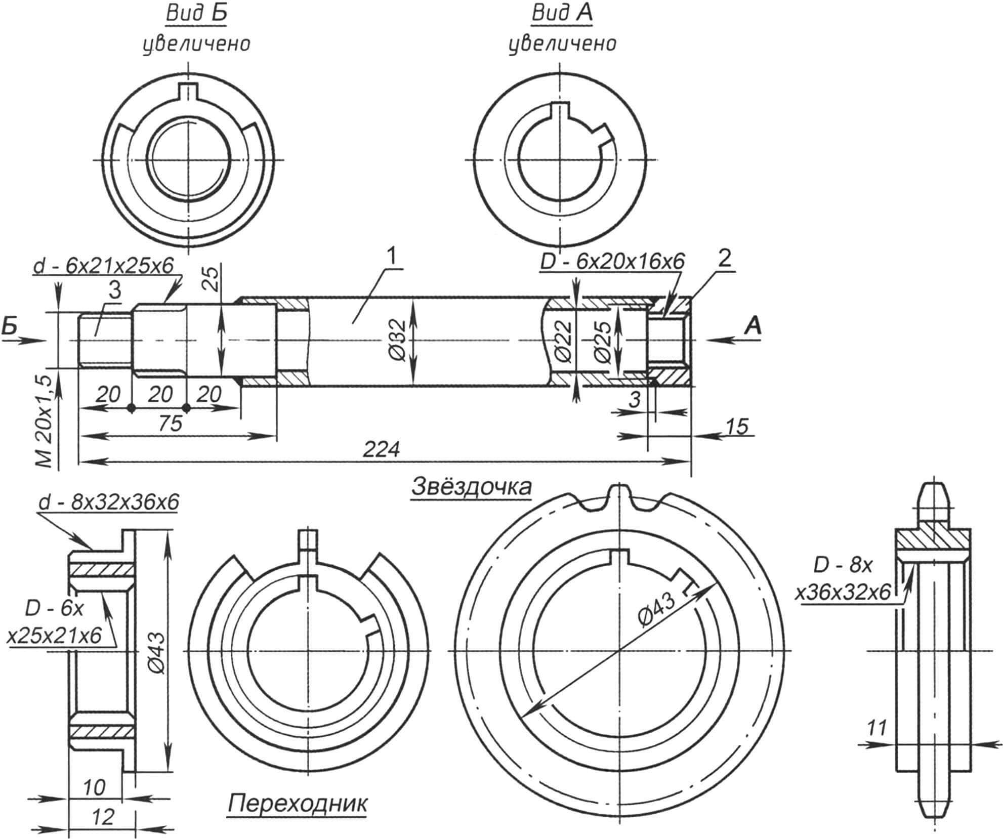
1 – extension; 2 — tip for attachment to the shaft; 3 – tip for drive gear
The gearbox has a gear ratio of 2.353.
To transfer rotation from the secondary (output) shaft to the drive shaft sprocket, it was necessary to make a welded extension from a pipe with splined tips. At one end, internal splines are cut directly into the pipe (for fitting the extension onto the shaft). On the other side there are external slots for the adapter, a seat for the bearing and an M20x1.5 thread for mounting on the sprocket extension, made on a welded tip.
Looking ahead, I note that exactly the same tip is welded to the drive shaft of the caterpillar, which is made from the tension rear axle of the caterpillar from the Buran snowmobile.
The snowmobile frame is spatial, welded from steel pipes of rectangular, square and round sections.
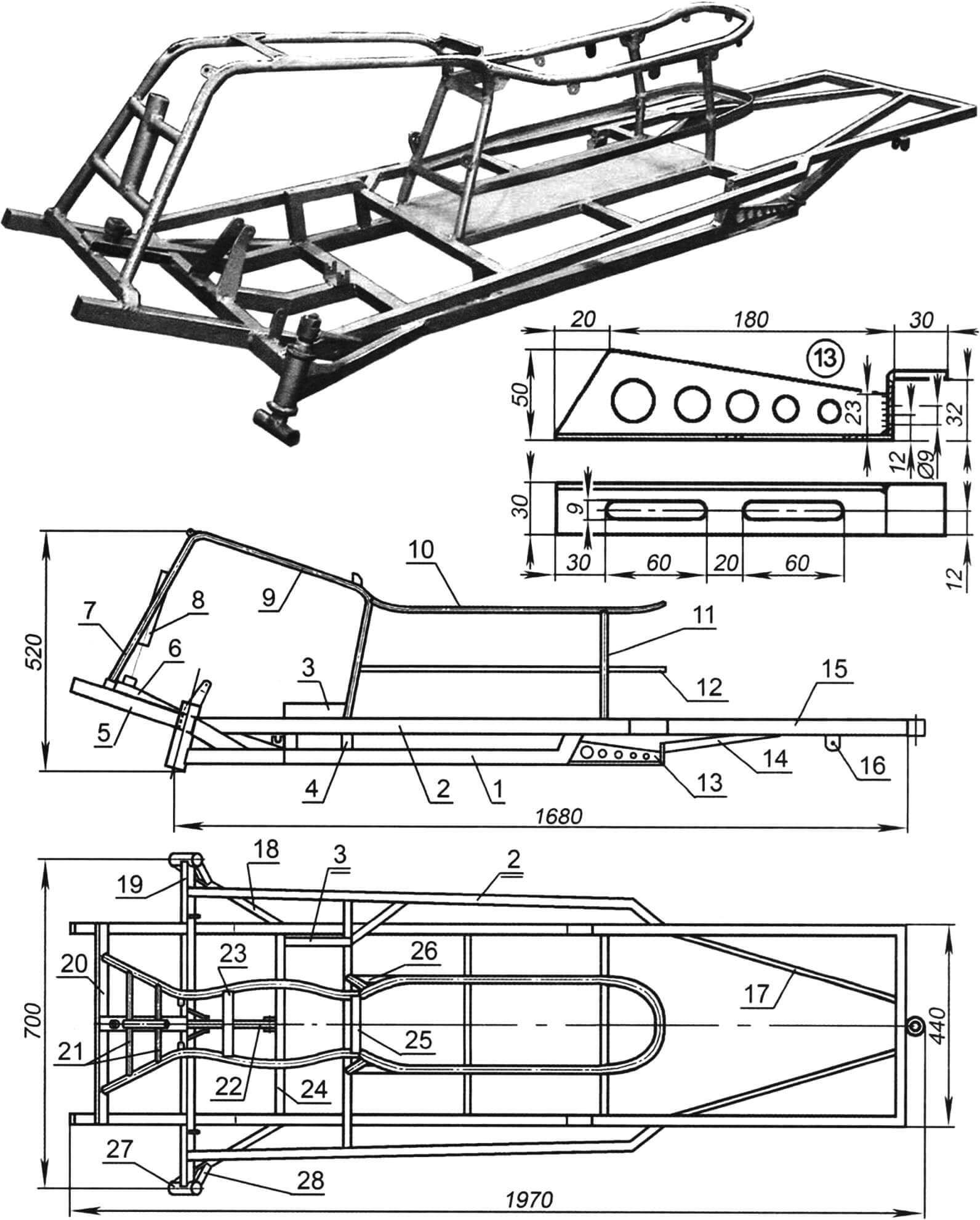
1 — lower spar (pipe 28×25, 2 pcs.); 2 — upper spar (pipe 20×20, 2 pcs.); 3 — L-shaped bracket for fastening the support bearing housing of the power unit output shaft extension (pipe 28×25); 4 — braced interspar strut (pipe 20×20); 5 — stem (pipe 28×25, 2 pcs.); 6 — support bar for the steering shaft cup (steel sheet s3); 7 — steering shaft cup (pipe Ø32); 8 — steering column (pipe Ø32); 9 — arc stand, 2 pcs.); 10 — seat frame (pipe Ø20); 11 — seat post (pipe Ø20); 12 — tool box strapping (steel angle 20×15); 13 — welded bracket for fastening the track block and track tension (2 pcs.); 14 — bracket strut (pipe 20×20, 2 pcs.); 15 — half-frame of the trunk area (pipe 20×20); 16 — rear shock absorber mounting eye (steel s4, 2 pcs.); 17 — strut of the trunk half-frame (pipe 15×15, 2 pcs.); 18 — strut of the lower spar (pipe 28×25, 2 pcs.); 19 — traverse (pipe 28×25); 20 — cross member of stems (pipe 28×25); 21 — cross members of the steering column suspension (pipe Ø16); 22 — engine subframe (pipe 28×25); 23 — support coupler (steel plate); 24 — cross member of the lower side members (pipe 28×25); 25 — fuel tank tie-lock; 26 — longitudinal element of the seat niche (pipe 20×20, 2 pcs.); 27 — king pin bushing (bicycle, reinforced, 2 pcs.); 28 — strut of the pin bushing (pipe 20×20, 2 pcs.)
The frame is based on two paired tubular spars – upper and lower. The upper spar of each pair is made of a pipe with a cross-section of 20×20 mm. Most of the auxiliary elements are made from the same pipe: intermediate cross members, struts and even the rear frame of the luggage area. The lower spars are made from a pipe with a cross-section of 28×25 mm – this is the thickest pipe in the frame structure. The front yoke, front cross members and consoles, and sub-engine ridge are made from the same pipe.
It must be said that the frame pipes are of small cross-section and not even thick-walled. Therefore, in the places where I drilled holes, I inserted bushings into them and welded them in a circle.
The frame superstructure (upright, arch) is made of a round pipe with a diameter of 20 mm – from old chairs, thin-walled, but quite strong. It was just a little difficult to weld them, but if you do this using a semi-automatic machine, the process becomes much easier. The trunk frame under the seat, as well as the frame of the middle part of the platform, is made from a 15 mm equal-flange angle. Between these frames I put long items, such as skis. The steering shaft column – made from a pipe with a diameter of 32 mm – is built into the front part of the superstructure. The kingpin bushings are cut from bicycle frames and welded to the ends of the crossbar. The track tensioning brackets are also integrated into the frame (welded to the rear ends of the lower side members). These same brackets also serve as attachment points for the caterpillar balance shaft bearing housings to the frame. In addition, numerous ears and eyes for installing the power unit, fuel tank, seat, shock absorbers, etc. are welded to the frame elements.
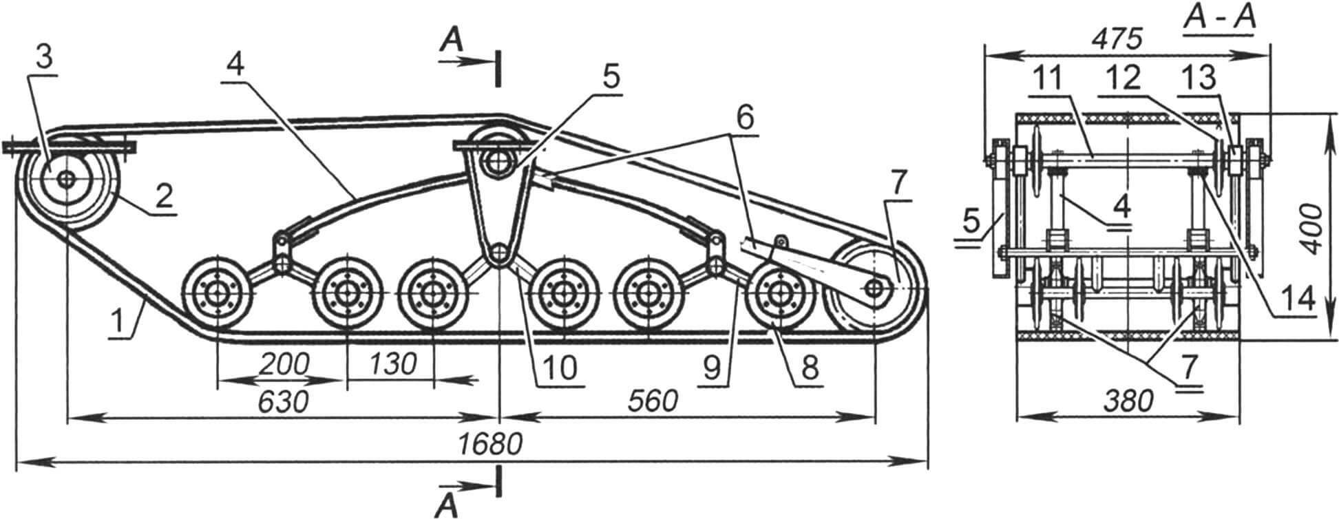
1 – caterpillar; 2 — caterpillar drive gear (2 pcs.); 3 — caterpillar drive shaft assembly; 4 — spring (2 pcs.); 5 — bracket for balancing block (2 pcs.); 6 — pendulum lever of the tension axis (2 pcs.); 7 — caterpillar tension gear (2 pcs.); 8 — support roller (10 pcs.); 9 — outer trolley (2 pcs.); 10 – middle trolley; 11 — axis of the balancing block; 12 — support roller (2 pcs.); 13 — housing with bearing for the axis of the balancing block (2 pcs.); 14 — bracket for fastening the spring to the axis of the balancing block (2 pcs.)
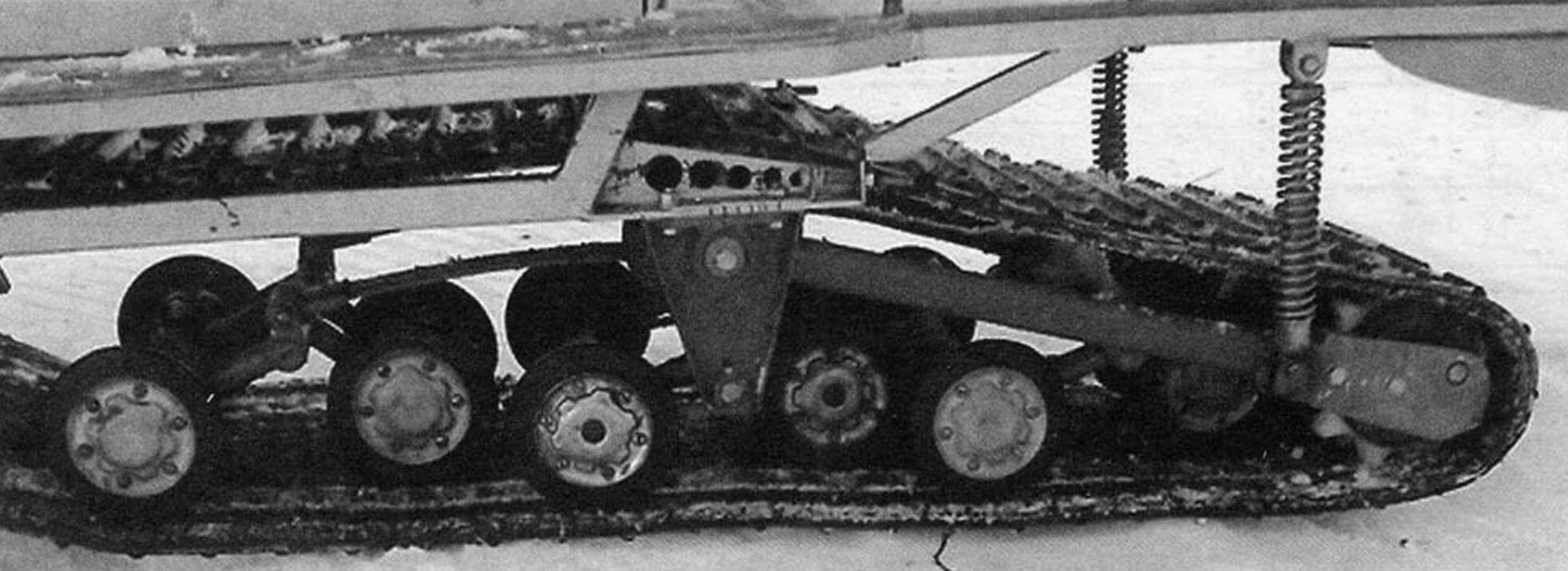
The track block (more precisely, its longitudinal half) was borrowed from the old industrial snowmobile “Buran”. Why half? Yes, because, firstly, it’s easier. Secondly, there are fewer costs and a simpler design. Well, thirdly, I intended to ride not on virgin snow, but in the footsteps of the “pioneers”.
However, in combination with a pair of fairly wide skis, the snowmobile confidently overcomes both deep snowdrifts and freshly fallen “powder”.
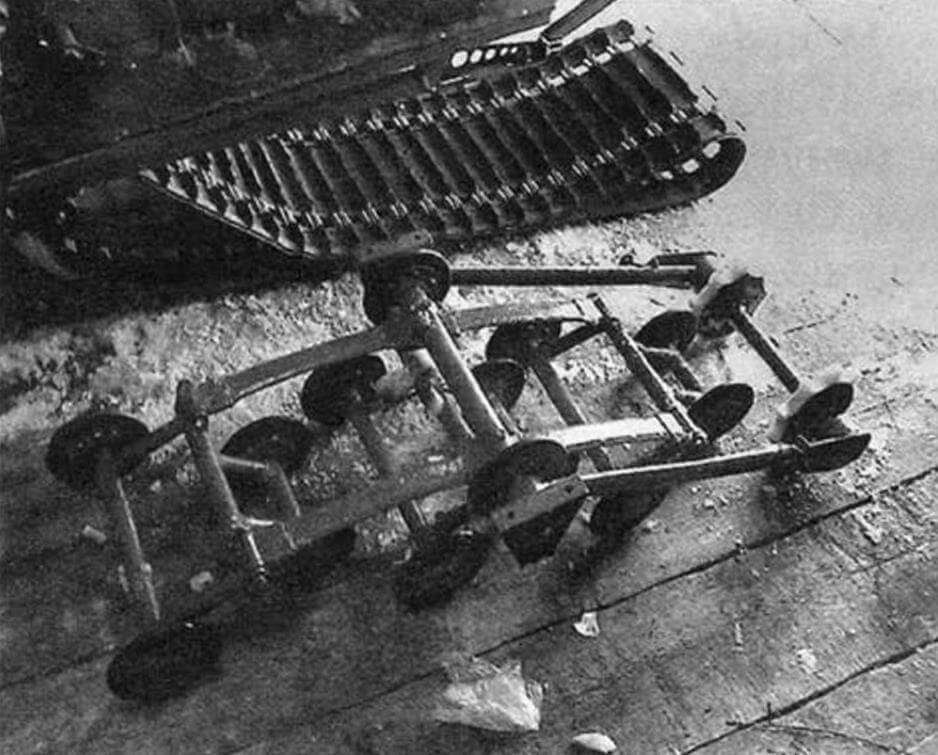
The outer bogies have been redone – the springs have been removed, and the bushings are welded together, since the bogies balance on their own, sitting on their axis at the ends of the springs.
The track tension unit has also been redone. The front ends of its pendulum arms sit on a common axis with a spring balancer assembly, and the rear ends are suspended on homemade spring shock absorbers to the frame.
The snowmobile’s propulsion system is a rubber track 380 mm wide (Buran has two of these). The caterpillar drive is carried out from the drive shaft through a pair of 9-tooth Buranovsky nylon wheels. The drive shaft is tubular. As noted earlier, it is made from a Buranovsky rear tracked axle, mounted in 80205 bearings, the housings of which are attached directly to the upper frame side members. The tension of the caterpillar is carried out by a tension axis with gear wheels (the same as the drive ones) through a pair of pendulum arms mounted on the axis of the balance trolley (by moving its bearings along the frame side members). The tension shaft of the caterpillar (or rather, the axle, since this part does not transmit torque) with gear wheels is also Buranovsky. The length of the track’s contact with the road is just over a meter.
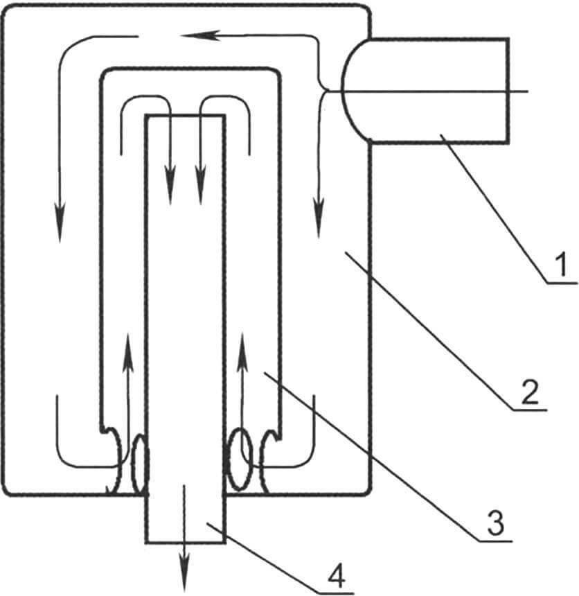
1 — inlet pipe; 2 – body; 3 — muffler; 4 — exhaust pipe
Previously, propulsors were built with a support glide ski. They are good on “puffy” snow and snowdrifts, but are very sensitive to hard road irregularities. They not only transmit discomfort to the driver, but also cause breakdowns of the tracks and even the slide itself. Therefore, this time I decided to make a mover with a rubber track and road wheels, since I intended to drive on rolled snow and even ice.
The snowmobile transmission, as they say, couldn’t be simpler, although not without its quirks. It consists of a single-stage chain drive from an IZH motorcycle with a pitch of 15.875 mm with a pair of sprockets: the drive has 15 teeth, the driven has 21, that is, the gear ratio is 1.6. The secondary (output) shaft of the power unit is extended by a pipe with internal splines at the end mounted on the shaft and a splined tip at the other. The free end of the extension is installed in bearing 80205, the housing of which is fixed to an L-shaped bracket welded to the frame. The drive sprocket of the chain drive is mounted on this tip through an adapter with internal and external splines. The driven sprocket is mounted (also through a spline adapter) on the splined tip of the track drive shaft. I made adapters from gears: annealed, sharpened, milled. Thanks to the spline adapters, the sprockets (and, consequently, the gear ratio) are easy to change even in the field to suit road conditions (more precisely, to suit the density and depth of the snow cover).
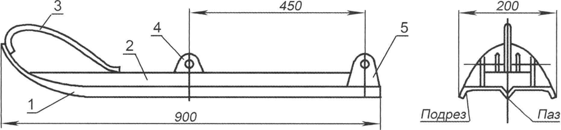
1 – runner; 2 – amplifier; 3 – bow; 4 — shock absorber mounting eye; 5 — lever mounting eye
The snowmobile’s steerable skis are homemade, 900 mm long (the blank is 1000 mm) and 200 mm wide. Made from steel sheet 2 mm thick. The runners are stamped: there is a triangular groove in the middle, and flanges-undercuts along the edges, curved upwards at the front (contact surface with snow – 800 mm). On top of the runners are welded longitudinal stiffening ribs of a U-shaped section, curved from the same steel sheet, and to them are ears and eyes for attaching suspension units, and in front are arms made of 10-mm steel rod.
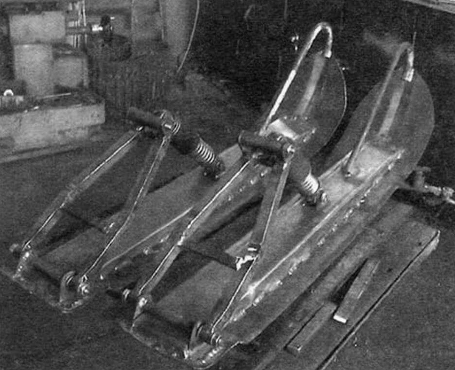
Each ski has a suspension consisting of a shock absorber (from a Tula scooter) and a homemade lever made from a 20×20 mm square pipe.
Steering is of mixed type. The steering wheel itself is a motorcycle lever, and the rest is like a car. The steering shaft is a “breaking” one with a cardan joint and even a unique steering mechanism. I made it a “breaking point” because it did not fit into the “parallel” with the pivot bushings (but in general, a straight shaft is better). It should be noted that the lower end of the shaft is structurally in front of the swing arms and rods, and the bipod is directed backwards. In this situation, when turning right, the steering wheel had to be turned to the left, and vice versa, which was contrary to common sense. Therefore, it was necessary to introduce a steering mechanism that serves to coordinate the rotation of the steering wheel and the direction of the skis. The mechanism consists of a pair of identical gears in a housing. The drive gear is mounted on the end of the steering shaft by means of a splined connection, and the shaft of the driven gear is connected (welded, although it is advisable and easy to make this unit also dismountable) with a T-shaped bipod. From the bipod through the steering rods and steering knuckles, the skis are now simultaneously turned in the same direction in which the steering wheel is turned.
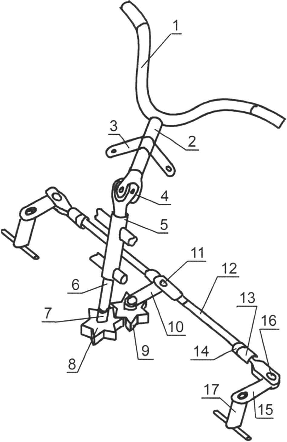
1 — steering wheel (bicycle); 2 — upper elbow of the steering shaft; 3 — support bracket for the upper bend of the steering shaft (furnishings);
4 — cardan joint; 5 — steering column; 6 — lower elbow of the steering shaft; 7 — clamp for the splined connection of the lower elbow and the gear shaft; 8 — drive shaft-gear; 9 — driven gear shaft; 10 – bipod; 11 — axis of the bipod and steering rods; 12 — steering rod (2 pcs.); 13 — tip for adjusting the length of the tie rod (2 pcs.); 14 — locknut 15 — steering lever (2 pcs.); 16 — rod and lever axis (2 pcs.); 17 — steering knuckle (2 pcs.)
Equipment. The fuel tank is welded from two tanks from the Riga moped. The seat is from a Minsk motorcycle and is mounted on stands covered with duralumin sheets. There is a tool box under the seat, and between the box and the floor there is a free niche with an opening at the back. If necessary, I put skis, a shovel and other long objects in it. The hood is a redesigned front part of the sidecar (side trailer) of the Java-350 motorcycle. Electrical equipment is standard. The headlight is from a Minsk motorcycle.
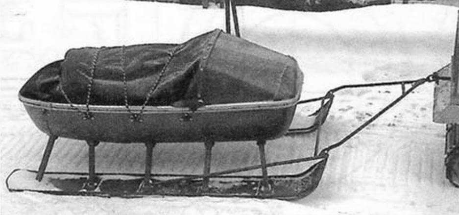
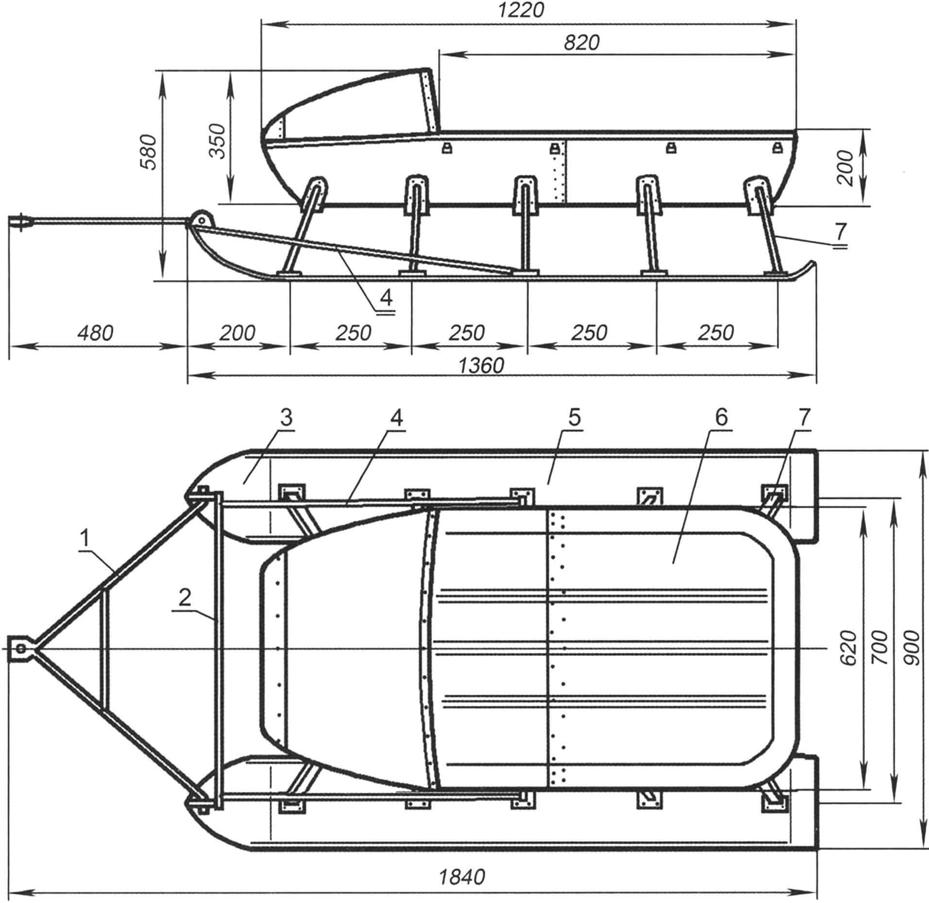
1 – drawbar; 2 – cross member; 3 — bracket-eye (2 pcs.); 4 — thrust (2 pcs.); 5 — ski (2 pcs.); 6 — body; 7 – stand (10 pcs.)
The sled trailer is homemade. I believe that it is better to have a small sled than a large trunk on a snowmobile: if you get stuck somewhere, you can unhook the sled, make a path, and attach it again. The body was once the body of the side trailer of the Java-350 motorcycle, or rather, what was left of it after the hood for the snowmobile itself was made. I shortened it by cutting about 200 mm in the middle. Then I riveted the front and back parts with pop rivets. Under the body I placed several cross members made of a rectangular pipe 40×20 mm, one of the wide walls of which was left as ears at both ends. The ears were attached to the sides of the body with rivets.
The body is mounted on skids made of aluminum busbar panels using tubular racks with a square section of 20×20 mm. The uprights are welded at the top to the crossbars with lugs and at the bottom – to the “heels” – steel square plates 2 mm thick. The “heels” were riveted to the ski runners with the same rivets.
I would like to note that the drawings of the components are not working, but for informational purposes: some do not show all the dimensions (for example, frames), and somewhere something may not match, since the drawings were made based on a ready-made design.
In general, I believe that making a structure according to drawings is production, not creativity.
V. SMIRNOV, Syava village, Nizhny Novgorod region.
Recommend to read
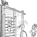 Gym in your bedroom
“Hypodynamia, old age, and shortness of breath…” — so goes a well-known song. Indeed, in our age of widespread mechanization and computerization, the question of maintaining an active...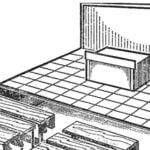 HYDRAULIC… CLASS
Imagine you are in class technical schools. Class is in session. Lecturer for the Department sets the course, and the students, as expected, sitting at desks and listening attentively....
